
![]() PICOGLF50KW384V240VS Off Grid Inverter Charger
PICOGLF50KW384V240VS Off Grid Inverter Charger
PICOGLF50KW384V240VS
PICOGLF50KW384V2083P
PICOGLF30KW300V240VS
PICOGLF30KW300V2083P
PICOGLF30KW300V4803P
Installation Guide
![]() Read the manual carefully. Follow all warning and operating instructions contained in the manual before operating the inverter. Keep the manual for future reference.
Read the manual carefully. Follow all warning and operating instructions contained in the manual before operating the inverter. Keep the manual for future reference.
The information included in this manual is based on the product at the time of publication. However, this manual is subject to change without prior notice. AIMS Power™ reserves the right to continuously improve the product. In addition, the illustrations in this manual are only meant to help explain system configuration concepts and installation instructions. Your system or application may be different than the examples used in this manual.
Exclusion of Liability
AIMS Power cannot monitor the compliance to this manual, nor the conditions and methods of installation, operation, usage, and maintenance of the solar controller. Improper installation may result in damage to property and, as a result, bodily injury. We assume no responsibility or liability for loss, damage, or costs that result from, or are in any way related to, incorrect installation, improper operation, or incorrect use and maintenance. AIMS Power reserves the right to make changes to the product, technical data or assembly, and operating instructions without prior notice.
SYMBOLS
| SYMBOL | DESCRIPTION |
| Grounding point | |
| Refer to instructions | |
| Properly dispose | |
| Beware of dangerous electrical voltage. The inverter operates at high voltages! | |
| CE mark The inverter complies with the requirements of the applicable CE guidelines. | |
| SAA mark The inverter complies with the requirements of the applicable Australia guidelines. | |
| UL mark The inverter complies with the standard of UL1741. | |
| CSA mark The inverter complies with the standard of CSA22.2. |
Safety Instructions
Warning: The warnings, cautions, and instructions discussed in this instruction manual cannot cover all possible conditions and situations that may occur. It must be understood by the operator that common sense and caution are factors that cannot be built into this product and must be supplied by the operator. to prevent electric shock.
- To avoid the risk of fire and electronic shock, make sure existing wiring is in good electrical condition and the wire is not undersized.
- This equipment contains components that may produce arcs and/or sparks. To prevent fire and/or explosion, do not install in compartments containing batteries or flammable materials including any space containing gasoline-powered machinery, fuel tanks, joints, fittings, or areas that contain fuel.
- To reduce the risk of electrical shock, disconnect both AC and DC power from the inverter before attempting any maintenance or cleaning. Simply turning off the controls will not reduce this risk.
- Never smoke or allow sparks or flames close to the inverter or solar system.
- Remove personal metal items such as rings, bracelets, necklaces, and watches when working with this product.
- Do not operate if under the influence of alcohol or drugs. Read warning labels on prescriptions to determine if your judgment or reflexes are impaired while taking drugs. If there is any doubt, do not operate the box.
- People with pacemakers should consult their physician(s) before using this product. Electromagnetic fields near a pacemaker could cause interference to or failure of the pacemaker.
- Keep inverter away from children. Don’t install the inverter where it is accessible to children.
- Properly maintain all equipment. Check all wiring, batteries, inverters and charge controllers.
- Ensure someone is within close range when working with any type of electrical equipment.
- Do not expose the inverter to rain, snow, spray, damp area, bilge or dust.
- Do not cover or obstruct the ventilation openings. Install in a well-ventilated area. Do not install the inverter in a zero-clearance compartment. Overheating may result. Allow at least 12” of clearance around the inverter for airflow. Make sure that the air can circulate freely around the unit. A minimum airflow of 145CFM is required.
- See Warranty Instructions for servicing the inverter. Only a professional electrician should service the inverter.
![]() WARNING INSTALLATION & MAINTENANCE SHOULD BE PERFORMED BY A PROFESSIONAL ELECTRICIAN/TECHNICIAN. ALL ELECTRICAL INSTALLATIONS SHOULD FOLLOW LOCAL CODES.
WARNING INSTALLATION & MAINTENANCE SHOULD BE PERFORMED BY A PROFESSIONAL ELECTRICIAN/TECHNICIAN. ALL ELECTRICAL INSTALLATIONS SHOULD FOLLOW LOCAL CODES.![]() NOTE
NOTE
CAREFULLY INSPECT ALL PARTS AND MAKE SURE THERE IS NO DAMAGE. NOTIFY THE MANUFACTURER OF ANY DAMAGES BEFORE ACCEPTING DELIVERY AND INSTALLING THE INVERTER.![]() NOTE
NOTE
Do not close any breakers until all equipment is completely connected and inspected.![]() Warning
Warning
Use proper grounding, using appropriate cable and fuse size.![]() Danger
Danger
Before performing checks or maintenance, open (off) AC breaker, turn off start switch, then open (off) DC breaker. Wait 5 minutes for energy to dissipate. Measure DC and AC voltages with a multimeter and ensure there is no voltage between the DC side and the AC side. The display will slowly dim and disappear as the voltage drops.![]() Danger
Danger
Don’t make any connections or open doors when the inverter is powered on. Shock may occur.
Product Introduction
Summary
Our PICOGLF series off-grid inverter is one of the largest DC to AC inverters in the world. The Global LF Series Pure Sine Wave Inverter is a combination of an inverter, trickle battery charger, and an AC auto-transfer switch into one complete system, with a peak conversion efficiency of 94%.
It is packed with unique features and it is one of the most advanced inverters on the market today. It features power factor correction, customizable AC and DC operation, and a pure sine wave output with unprecedentedly high surge capability to meet the demanding power needs of inductive loads without damaging the equipment.
When utility AC power cuts off (or falls out of acceptable range), the transfer relay is de-energized, and the load is automatically transferred to Inverter mode. Once the qualified AC power is restored the relay is reenergized and the load is automatically reconnected to AC bypass mode.
The priority is programmable.
Features
- Advanced short circuit, overload, over temperature protections ensure a service life of up to 15 years or more.
- Two types of startup modes: Soft Start and Variable Frequency Start. Users can select mode according to the type of load.
- Adjustable output frequency.
- Adjustable AC output voltage. The output voltage can be set between -40 % to +20 % of the rated voltage.
- Adjustable DC voltage range. Over-voltage point, under-voltage point,
over-voltage recovery point, and under-voltage recovery point can be set via the LCD panel. - Powerful data display and fault instruction function. The LCD can display DC input voltage, output frequency, phase voltage, phase current, AC bypass input voltage, power generated, time and date, temperature, fault code display.
- Pure sine wave output with quick transfer less than 50ms, minimal waveform distortion, and stable output voltage.
- Low-frequency transformer with isolated DC and AC busbars to eliminate interference.
- Wide input voltage range, customizable to customer’s requirement. Input voltage range of 100300V or 200-600V or 400-800V, suitable for solar/wind system without using backup batteries and charge controller. it can save many costs and maximize the use of solar/wind energy.
- Using SVPWM space vector algorithms, high conversion efficiency, high instantaneous power, and low losses conversion efficiency up to 94%.
- Output AC power compatible for all types of home electric equipment, sensitive electronics, electric motors, etc.
- European CE (EMC & LVD) certified and UL1741 & CSA22.2 listed.
Physical Layout
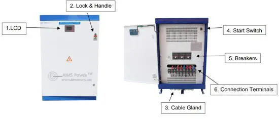
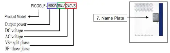
Example: PICOGLF50KW384V240
| No. | Name | Description |
| 1 | LCD Display Screen | Displays inverter’s operating status. Some functions are settable using the LCD display. Battery voltage, AC output voltage, AC current, frequency, work mode, and faults. |
| 2 | Lock & Handle | Inverter lock and handle for the main door. |
| 3 | Cable Gland | The input and output wire throughputs. |
| 4 | Start Switch | Start switch to charge capacitors for starting the inverter. |
| 5 | Breakers | DC input and AC output breaker. |
| 6 | Connection Terminals | DC input terminal & AC output terminal. |
| 7 | Name Plate | Basic inverter specifications are listed on the nameplate including the serial number. |
Technical Information
Derating
Reducing the output power is a way to prevent inverter overload or damage. When the operating environment temperature and altitude are too high, both can cause a decrease in the inverter’s output power.
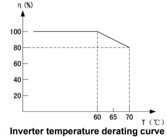
η=(Pout/Phnom )x100
T = environment temperature
Pout is the off-grid inverter’s actual maximum output power Phnom is the off-grid inverter’s allowed max. output power
Unpacking the Inverter
The product has been tested, thoroughly inspected, and packaged to withstand transportation. It is important to check the package and inverter before installing.
Be sure to inspect for any damage or incorrect quantities BEFORE signing for the product. If you accept the product, make sure to have the carrier NOTE the damage before signing.
The nameplate shows the inverter’s model and other important information. Confirm you ordered and that you received the correct inverter.
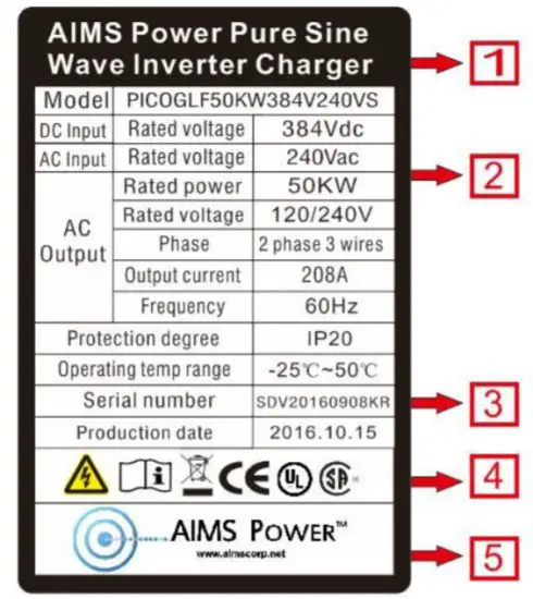
| NO. | Description |
| 1 | AIMS Power Logo and product name. |
| 2 | Inverter model and parameter information. |
| 3 | Serial number. |
| 4 | Certifications and safety symbols. |
| 5 | Company info. |
![]() Note!
Note!
Photos are for reference only, check the nameplate on the inverter.
Installation
Location
- The inverter must be installed in a cool dry area. Water, dirt, and dust will damage the inverter.
- A 1ft clearance around the inverter is recommended.
- Installation must comply with local standards and codes.
- Do not install the inverter in a flammable or explosive area or a place where flammable or explosive materials are stored.
- Do not install the inverter in areas where the inverter is vulnerable to lightning strikes.
- Do not install the inverter in a high salt, humid environment.
- Inverter has a rating of IP20. Install indoors and out of direct sunlight.
- Place inverter on a solid, sturdy, flat surface that can handle the inverter’s weight.
- The ideal temperature should be maintained within -13 to 122°F and humidity not exceeding 95%.
- The inverter should be installed vertically.
- Do not allow the inverter to tilt forwards.
- Never install the inverter horizontally.
- Install the inverter so the LCD is easy to access and read.
- The inverter should have plenty of airflows all around the inverter for proper cooling fan operation.
- Don’t install the inverter where passersby or children can tamper or access the unit.
Electrical Connection
As mentioned several times in this manual, installation should be done by a licensed professional. The electrical connections should be tested immediately after the installation is completed.
Prechecks
- All electrical connections must meet local electrical codes.
- Incorrect wiring and/or installation may damage the inverter and may cause bodily harm.
- Before making any connections or performing maintenance to the inverter, make sure all
- power is off and no voltage is present on the AC and DC sides.
- Test for correct grounding, using proper cable and fuse sizes.
- Use a fuse or breaker 12 inches off the battery bank.
- Confirm the front panel breakers are in the “OFF” position and confirm all connections are properly wired.
- Check that the DC input breakers are in the “OFF” position.
- The cable between the battery and the inverter should be as short as possible to avoid voltage drop.
- Never turn off the DC input breaker with the inverter on or under a load, damage to the breaker or the inverter will occur.
- Ensure all air vents are free from obstructions and clear of dust and debris.
- Don’t connect the ground wire (PE) of the cabinet and the neutral wire (N) together.
NOTE: Do not over shut DC breaker off during operation. To shut AC off, use AC breaker first, then disengage AC start switch. To shut down the inverter completely, follow the above steps first then turn off the DC breaker. Shutting off the DC breaker during operation and under a load will damage the breaker and cause arcing. 
Terminals | Description |
| DC positive input terminals | |
| DC negative input terminals | |
Ll, L2 | AC input terminals, connect with AC grid or generator |
Ll, L2, N | AC output terminals, connect with AC load panel |
PE | Earth ground |
Terminal Block

![]() Warning!
Warning!
- Do not reverse the polarity when connecting to DC input terminals. Confirm your wires are connected properly. Use the proper size cable and use the bigger cable to handle voltage drop for long-distance runs.
- REVERSE POLARITY IS NOT COVERED UNDER WARRANTY.
- Source ground to case ground must be isolated and wire length should be as short as possible.
- After all wire connections have been made, check all voltages to ensure the voltages are within the inverter’s specification.
- Never operate any inductive motor larger than 30% of the output of the inverter due to high startup surge.
- When turning on the DC input breakers, the breaker may trip or pop the first time. This is normal as the large capacitors are rapidly charging. If this happens, simply reset the DC breakers.
- When powering on the inverter, we recommend turning on the output circuit breaker first, then turning on the start switch allowing a soft start of AC loads to avoid any damage by large inrush current to inverter.
- Before performing checks or maintenance, open (off) AC breaker, turn off start switch, then open (off) DC breaker. Wait 5 minutes for energy to dissipate. Measure DC and AC voltages with a multimeter and ensure there is no voltage between the DC side and the AC side. The display will slowly dim and disappear as the voltage drops. The inverter may still be live and have voltage present in the off position due to the large capacitors. Never touch any connection prior to testing with a multimeter.
- When the inverter is operating normally, it is typical to see a rise in temperature. The cooling fans will start when the temperature reaches @ 113°F.
- Do not open the inverter’s door or touch any wire while in operation.
![]() NOTE
NOTE
When the inverter is running, it is normal for the inverter to get warm. To avoid injury, only touch the LCD display and start/stop the switch. DO NOT TOUCH ANY BREAKERS WHILE THE INVERTER IS OPERATING. THIS MAY CAUSE BODILY HARM AND RUIN THE INVERTER. After all connections are made and voltages are verified with a multimeter, proceed to the startup procedure in section 6.
LCD Display Layout
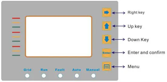
LED Indicators
There are 5 LED lights on the panel: Grid, Run, Fault, Auto, Manual.
Table7-1 LED Indicator Direction
| LED Indicator | Color | Instructions |
| Amber | AC bypass priority mode indicates the AC grid input condition. | |
| Run | Green | Battery priority mode indicates the battery supply condition. Inverter mode. |
| Fault | Red | System fault. |
| Auto | Blue | Inverter running indicates the inverter is working normally. |
| Manual | Illuminated | Variable frequency mode, the inverter is working in variable frequency mode. |
*When in inverter mode, the LED will be blue/green or blue/amber. This is normal.
Fault Code
DCU OVER DC over-voltage
DCU UNDER DC under-voltage
OVER LOAD Current over-load
MOD Module error
OUTErr Output voltage unbalances (This error is only for 3 phase output, single-phase output without this error display).
Diagram of the power-on sequence
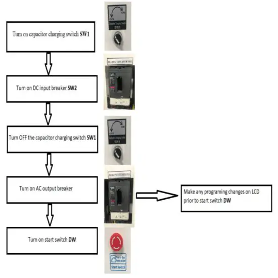
If any inverter parameters need to be made, follow instructions on page 15 LCD Panel Operating Instructions. All parameters must be set prior to engaging start switch DW.
LCD Display Interface Overview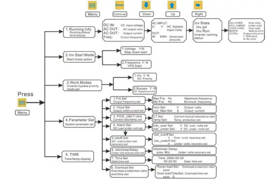
LCD Panel Operating Instructions
Inverter power on, the first interface display parameter, press “down” key to display the following parameters: 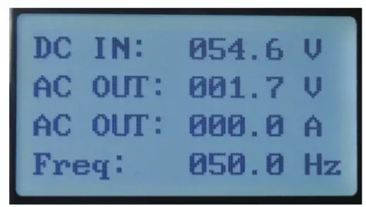
DC IN DC input voltage display
AC OUT AC output voltage display
AC OUT Output current display
Freq Output frequency display 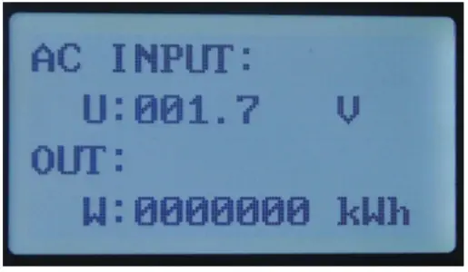
AC INPUT: AC bypass input
U: V Bypass phase voltage
OUT: Total generated amounts
W: KWH Generated amounts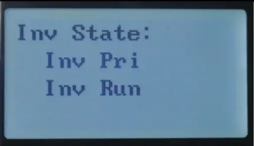 Inv State: Inverter working state:
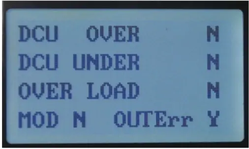 DCU OVER DC over-voltage
DCU UNDER DC under-voltage
OVER LOAD Over-load
MOD Module error
Fault display:” N” indicates no error, ”Y” indicates an error
OUTErr Output voltage unbalanced
**This error is only for 3 phase output. (NA for 240V)
- Fault alarm can be divided into automatic recovery and non-automatic recovery: When the LCD screen display MOD error and overload you need to manually restart, turn off the DC circuit breaker until the LCD screen is completely off and then turn on the DC circuit breaker; over-voltage, under-voltage, will automatically recover (the under-voltage recovery default setting is 10 minutes), and can be set according to the customer application.
Keypad function
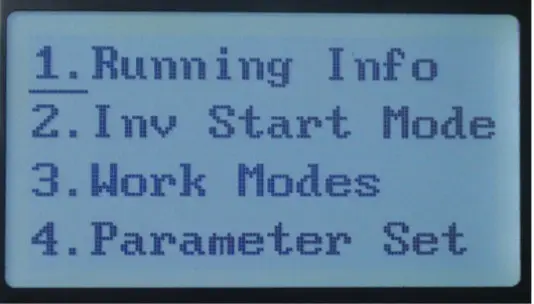
- Running Info Running state display
- Inv Start Mode Inverter Start mode
- Work Modes Working Mode
- Parameter Set System parameter setting
Press “ 2. Inv Start Mode ” displays the following 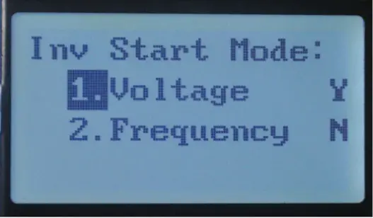
- Voltage Constant frequency step-down voltage Starting mode
- Frequency Variable frequency starting mode
Y: YES
N: NO
Press “ 3. Work Modes ” displays the following 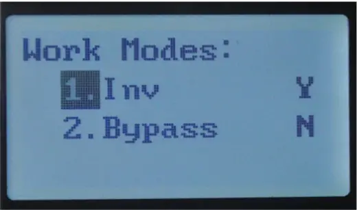
- Inv Battery priority mode
- Bypass AC bypass priority mode
Y: YES
N: NO
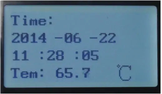
Time: Display current time and date
Tem: Environmental temperature display
Press “ 4. Parameter Set ” you will need to enter a password each time.![]() Note! If you want to adjust the parameter setting, please contact the manufacturer and ask for a password
Note! If you want to adjust the parameter setting, please contact the manufacturer and ask for a password 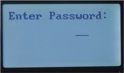
![]() Note! When the inverter is working, please don’t adjust the parameters set.
Note! When the inverter is working, please don’t adjust the parameters set.
If you want to adjust the parameter setting, please turn off the start button and the operation of the inverter.
The following settings are to be set by a qualified professional. If you are not qualified to make these changes, the damage will occur and not be covered under warranty. 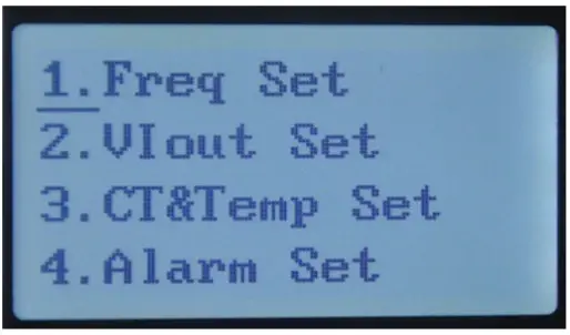
- Freq Set Frequency setting
- VIout Set Output voltage setting
- CT&Temp Set Current ratio setting and temperature Protection setting
- Alarm Set DC over-voltage and under-voltage setting
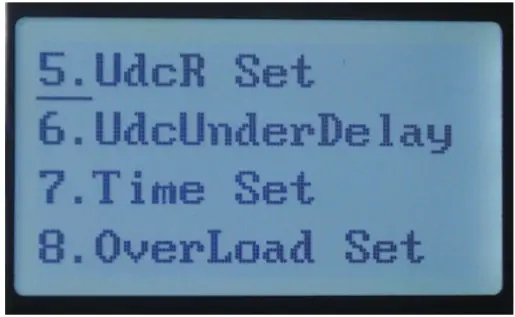
- UdcR Set
Recovery setting of DC over-voltage and Undervoltage - Udc Under Delay Default recovery time of under-voltage is 10 minutes
- Time Set Date and time setting
- Overload Set Overload times and overload time setting
Press “ 1. Freq Set ” output frequency setting display as following 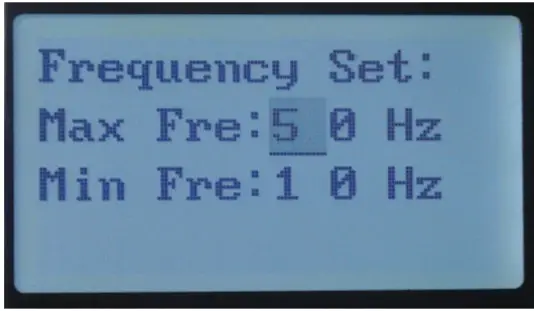
Max Fre: HZ Recommend maximum output frequency setting between 30-100Hz
Min Fre: HZ The minimum frequency of output Starting can’t less than 5Hz
Press “ 2. Vout Set ” output voltage and current setting display as following 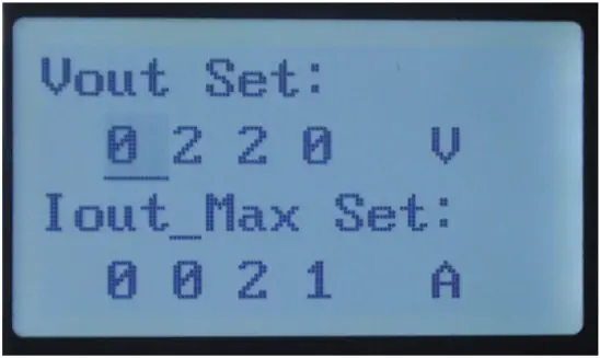
Vout Set Output voltage setting
Iout –Max Set: Output current setting
Note: Output Max Current default is the overload protection current value and can be lowered, Output voltage should be set to no more than 20% of the rated power. If the inverter is damaged by incorrect settings it will not be covered under warranty.
Press “ 3. CT&Temp Set ” Current and mutual inductance ratio and Protection temperature setting display as follows 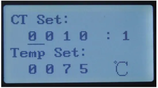
CT Set: Current and mutual inductance ratio setting
Temp Set: Protection temperature setting
Press “ 4. Alarm Set ” over-voltage and under-voltage setting display as following
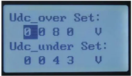
Udc-over Set: DC over-voltage protection setting
Udc-under Set DC under-voltage protection setting
Press “ 5. UdcR Set ” DC over-voltage and under-voltage recovery setting display as following 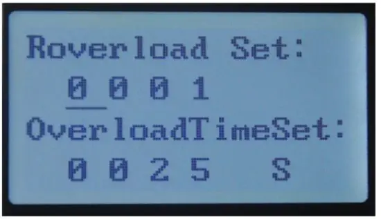
Udc-over Set: DC over-voltage recovery setting
Udc-under Set: DC under-voltage recovery setting
Press “ 6. Udc Under Delay ” Under-voltage recovery time setting display as following 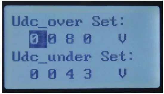
Udc Under Delay: Under-voltage recovery time setting
Min Minute
Press “ 7. Time Set ” to display as following 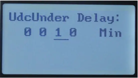
Time: Display date and time setting
Press “ 8. Over Load Set ” 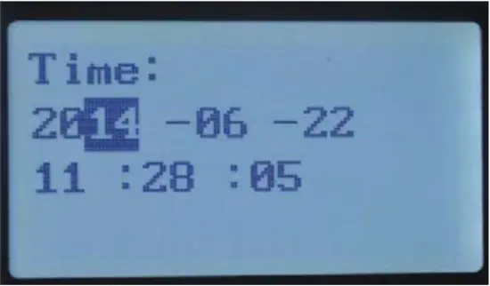
Recovery over Load Set: Overload times
setting Overload surge time
Malfunction and Troubleshooting
If a malfunction or alarm sounds, the malfunction LED will light up, LCD will display current malfunction or stop condition, please refer to the chart below for commons malfunction and troubleshooting steps.
| Condition code | Name | Phenomena | Cause value | Troubleshooting |
| State 01 | DC input voltage low | Inverter stopped working, No AC output, inverter restarts automatically | Battery voltage out of inverter’s DC range. DC input voltage lower than the min input voltage of the inverter | Check battery output the voltage on the inverter, ensure the output voltage is within spec of inverter. |
| State 02 | DC input Over voltage | Inverter stopped working, No AC output, inverter restarts automatically | DC input voltage higher than the maximum input voltage of the inverter | Check battery output. voltage or PV array voltage and ensure the output voltage is within spec of the inverter. |
| State 03 | Output overload | Inverter shut down, AC loads turn on and off | Load higher than the rated output power of the inverter. Battery bank too small | Ensure correct system design. This fault is usually caused by high surge devices that the inverter or battery bank can’t support. |
| State 04 | IPM fault | Inverter shut down, will no longer output AC power | Check for short circuit on AC output. If this fault appears frequently, please contact AIMS Power |
Under fault of MOD, overload, output error and fault alarm, turn off the DC input breaker for 1 hour to restart the machine.
Maintenance
![]() CAUTION
CAUTION
Before performing checks or maintenance, open (off) AC breaker, turn off start switch, then open (off) DC breaker. Wait 5 minutes for energy to dissipate. Measure DC and AC voltages with a multimeter and ensure there is no voltage between the DC side and the AC side. The display will slowly dim and disappear as the voltage drops. The inverter may still be live and have voltage present in the off position due to the large capacitors. Never touch any connection prior to testing with a multimeter.
Every 6 months
- Check all ventilation and fan airways. Blow air and clear all dust in the inverter and in the surrounding area. If a high level of dust is accumulating, relocate the inverter or find a way to keep dust at a minimum.
- Check the inverter cable connections. If loose, tighten according to the proper connection guidelines in this manual.
- Ensure the cables are not damaged, inspect for cracking, fraying, cut, or over heated wiring.
| Parts | Check the contents | Solutions |
| Input and output terminals | Loose | Tighten |
| Input and output cable | Condition of cable | Replace poor quality cable |
| Control board | Accumulation of dust and dirt | Using 392kPa-588kPa pressure dry compressed air to clean inverter |
| Bus capacitor | Discoloration or smell | Replace capacitor |
| Radiator Fan | Not working | Replace fan |
| Inside of cabinet | Accumulation of dust and dirt | Using 392kPa-588kPa pressure dry compressed air to blow off |
| Button cell | LCD doesn’t display Time | Replace the CR1220 Button Cell on the motherboard |
Warranty Conditions
All AIMS Power® products come with warranty coverage against defects as follows, from the date of purchase, unless otherwise indicated:
- 2-Year with optional extended warranties
Within the warranty coverage period, AIMS Power® will either repair or replace, at its sole discretion, the defective product. A refund may be issued if a defective product is not repairable or a comparable replacement is available. – We will never issue a refund. We will always have a replacement if the unit is not repairable. Our distributors offer their own return policy. AIMS only cover warranty issues.
Any shipping charges that occur as a result of a warranty return or exchange are NOT covered by the warranty
and are the responsibility of the customer.
The warranty does not cover the following:
- Products that AIMS Power® determines, in its sole discretion, to be free of any material or workmanship defects or flaws
- Products evidencing excessive wear, misuse or alteration
- Products with missing or defaced labels, stickers, or other identifying information
- Improper care or storage (e.g. water damage, exposure to extreme heat or cold temperatures)
- Alterations or customization
- Items that were purchased second hand, or from an unauthorized seller
- Items outside of the covered warranty period
AIMS Power
9550 Gateway Drive
Reno, NV 89521
775-359-6703
www.aimscorp.net
Specifications
| Model | 30KW | |
| Isolation mode | Low-Frequency Transformer | |
| DC Input | Rated voltage (Vdc) | 300V Operating: 270-430V DC Programming: 250-500V DC |
| Rated current(A) | 100A | |
| DC operating range | 270-430V DC | |
| Programmable range | 250-500V DC | |
| AC Output | ||
| Rated power (KW) | 30KW | |
| Rated voltage | 120/240V split 120/208V 3 phase 480 3 phase | |
| Output phases | Split phase I 3 phase – depends on the model | |
| Rated current (A) | 125A I 83.3A (phase current) | |
| Output frequency | 60Hz | |
| Output waveform | Pure Sine Wave | |
| Voltage accuracy | Load balance-i-:c1%, Unbalance load,5% | |
| Waveform distortion rate (THD) | Linear load 2%, Nonlinear loci,g,3% | |
| Dynamic Response | 5%, 550ms( load 0 – 100%) | |
| Power Factor (PF) | 0.95 | |
| Inverter Efficiency | >94% | |
| Electrical insulation properties | 2000Vac, 1 Minute | |
| Running mode | Working continuously can work 24h*7@50% load | |
| Output voltage (Vac) | 110/120/220/230/240/380/400/415/440VAC can be customized | |
| Phases | Single / Split] Three-phase optional – per order | |
| Protection Function | ||
| Overload Ability | 120% – 35 seconds, 150% – 5 seconds | |
| Protection | Input reverse polarity, under-voltage, over-voltage, output over-current, short circuit, overheating, etc. | |
| Display | LCD | |
| Communication port | RS485(Optional) | |
| Cooling method | Fan-cooled | |
| Short-circuit protection | No automatic recovery, need to restart the machine | |
| Working environment Mechanical dimension | ||
| Degree of protection | IP20(indoor) | |
| Working Altitude (m) | 52500m | |
| Working temperature | -15-‘+50 C | |
| Relative humidity | 0-90%. non-condensing | |
| Noise (1 meter) | 5.50dB | |
| Depth* Width * Height | 650x750x1100mm 1 24″ x 24.75″ x 42.50″ | |
| Weight (Kg) | 260Kq 1 5681b – 6501b | |
| Certifications | European CE (EMC & LVD) UL, CSA | |
| Model | 50KW | |
| Isolation mode | Low Frequency Transformer | |
| DC Input | Rated voltage (Vdc) | 360V |
| Rated current(A) | 139A | |
| DC operating range | 346-550V DC | |
| Programmable range | 320-600V DC | |
| AC Output | ||
| Rated power (KW) | 50KW | |
| Rated voltage | 120/240V I 120/208V | |
| Output phases | Split phase I 3 phase | |
| Rated current (A) | 208.3A 138.M I (phase current) | |
| Output frequency | 50Hz or 60Hz | |
| Output waveform | Pure Sine Wave | |
| Voltage accuracy | Load balance–; 1%, Unbalance load,C5% | |
| Waveform distortion rate (THD) | Linear load-. 2%, Nonlinear load- :3% | |
| Dynamic Response | 5%, 550ms (load 0 – 100%) | |
| Power Factor (PF) | 0.95 | |
| Inverter Efficiency | >94% | |
| Electrical insulation properties | 2000Vac, 1 Minute | |
| Running mode | Working continuously can work 24h7 | |
| Output voltage (Vac) | 110/120/220/230/240/380/400/415/440VAC can be customized | |
| Phases | Single / Split/ Three-phase optional – per order | |
| Protection Function | ||
| Overload Ability | 120% – 35 seconds, 150% – 5 seconds | |
| Protection | Input reverse polarity, under-voltage, over-voltage, output over the current, short circuit, overheating, etc. | |
| Display | LCD | |
| Communication port | RS485(Optional) | |
| Cooling method | Fan-cooled | |
| Short-circuit protection | No automatic recovery, need to restart the machine | |
| Working environment Mechanical dimension | ||
| Degree of protection | IP20(indoor) | |
| Working Altitude (m) | 52500m | |
| Working temperature | -15-+50(U | |
| Relative humidity | 0-90%. non-condensing | |
| Noise (1 meter) | 550dB | |
| Depth* Width ‘ Height | 710x750x1300mm1 31.5″ x 31.5″ x 49.5″ | |
| Weight (Kg) | 400Kg 19001b -9601b | |
| Certification | European CE (EMC & LVD) UL, CSA | |
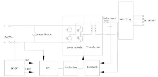
Electrical Diagram


 On-grid Charger 3-phase User Manual")


