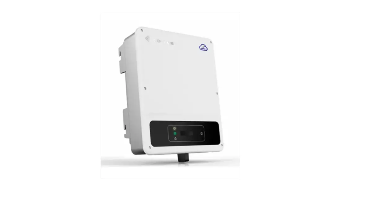
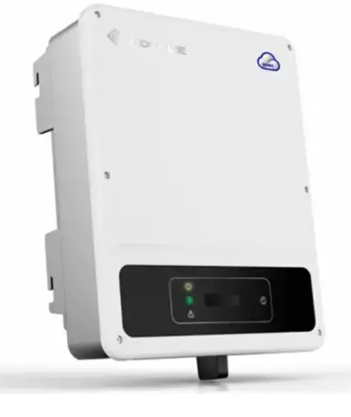
GOODWE GW5000-MS-US30 Grid Tied PV Inverter
Safety Precautions
General Disclaimer
- The information in this quick installation guide is subject to change due to product updates or other reasons. This guide cannot replace the product labels or the safety precautions in the user manual unless otherwise specified. All descriptions here are for guidance only.
- Before installations, read through the quick installation guide. For additional information, please see the user manual.
- All operations should be performed by trained and knowledgeable technicians who are familiar with local standards and safety regulations.
- Check the deliverables for correct model, complete contents, and intact appearance. Contact the manufacturer if any damage is found or any component is missing.
- Use insulating tools and wear personal protective equipment when operating the equipment to ensure personal safety. Wear anti-static gloves, clothes, and wrist strip when touching electronic components to protect the inverter from damage. The manufacturer shall not be liable for any damage caused by static electricity.
- Strictly follow the installation, operation, and configuration instructions in this guide and user manual. The manufacturer shall not be liable for equipment damage or personal injury if you do not follow the instructions. For more warranty details, please visit https://en.goodwe.com/warranty.
Safety Disclaimer
Warning
DC Side:
- Ensure the component frames and the bracket system are securely grounded.
- Connect the DC cables using the delivered PV connectors. The manufacturer shall not be liable for equipment damage if other connectors are used.
- Ensure the DC cables are connected tightly, securely, and correctly. Inappropriate wiring may cause poor contacts or high impedances, and damage the inverter.
- Measure the DC cable using the multimeter to avoid reverse polarity connection. Also, the voltage should be under the max DC input voltage. The manufacturer shall not be liable for the damage caused by reverse connection and extremely high voltage.
- The PV modules used with the inverter must have an IEC61730 class A rating.
AC Side:
- The voltage and frequency at the connecting point should meet the on-grid requirements.
- Additional protective devices like circuit breakers or fuses are recommended on the AC side. Specification of the protective device should be at least 1.25 times the maximum AC output current.
- Make sure that all the groundings are tightly connected. When there are multiple inverters, make sure that all the grounding points on the enclosures are equipotential bonding.
- You are recommended to use copper cables as AC output cables. If you prefer aluminum cables, remember to use copper to aluminum adapter terminals.
Product:
- Do not apply mechanical load to the terminals, otherwise the terminals can be damaged.
- All labels and warning marks should be visible after the installation. Do not scrawl, damage, or cover any label on the device.
- Unauthorized dismantling or modification may damage the equipment, the damage is not covered under the warranty.
- Install the inverter away from high magnetic field to avoid electromagnetic interference. If there is any radio or wireless communication equipment below 30MHz near the inverter, you have to:
- Install the inverter at least 30m(98.43ft) far away from the wireless equipment.
- Add a low pass EMI filter or a multi winding ferrite core to the DC input cable or AC output cable of the inverter.
- Warning labels on the inverter are as follows.
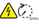
 | HIGH VOLTAGE HAZARD. Disconnect all incoming power and turn off the product before working on it. |
| Delayed discharge. Wait 5 minutes after power off until the components are completely discharged. |
 | Read through the guide before working on this device. |  | Potential risks exist. Wear proper PPE before any operations. |
 | High-temperature hazard. Do not touch the product under operation to avoid being burnt. |  | Grounding point. Indicates the position for connecting the PE cable. |
 | SGS Marking for the United States of America and Canada. |
| Do not dispose of the inverter as household waste. Discard the product in compliance with local laws and regulations, or send it back to the manufacturer. |
 | Type 1 Arc-Fault Circuit interrupter in PV side. |

Check before Power-on
| Sr No | Check Item |
| 1 | The product is firmly installed at a clean place that is well-ventilated and easy-to-operate. |
| 2 | The PE, DC input, AC output, and communication cables are connected correctly and securely. |
| 3 | Cable ties are intact, routed properly and evenly. |
| 4 | Unused ports and terminals are sealed. |
| 5 | The voltage and frequency at the connection point meet the inverter grid connection requirements. |
LED Indicators
| Indicator | Status | Description |
 | ON = EQUIPMENT POWER ON | |
| OFF = EQUIPMENT POWER OFF | ||
 | ON = THE INVERTER IS FEEDING POWER | |
| OFF = THE INVERTER IS NOT FEEDING POWER | ||
 | SINGLE SLOW FLASH = SELF CHECK BEFORE CONNECTING TO THE GRID | |
| SINGLE FLASH = CONNECTING TO THE GRID | ||
 | ON = WIRELESS IS CONNECTED/ACTIVE | |
| BLINK 1 = WIRELESS SYSTEM IS RESETTING | ||
| BLINK 2 = WIRELESS ROUTER NOT CONNECTED | ||
| BLINK 4 = WIRELESS SERVER PROBLEM | ||
| BLINK = RS485 IS CONNECTED | ||
| OFF = WIRELESS IS NOT ACTIVE | ||
 | ON = A FAULT HAS OCCURRED | |
| OFF = NO FAULT |
Product Introductions
Parts Introduction
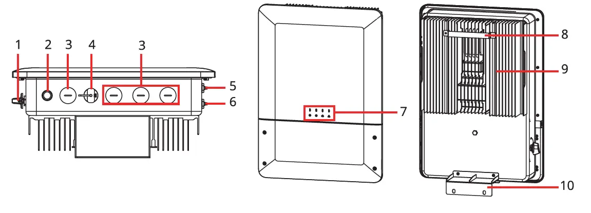
- DC Switch
- Button For Ezlink Reset[1]
- Wiring Conduit Hole
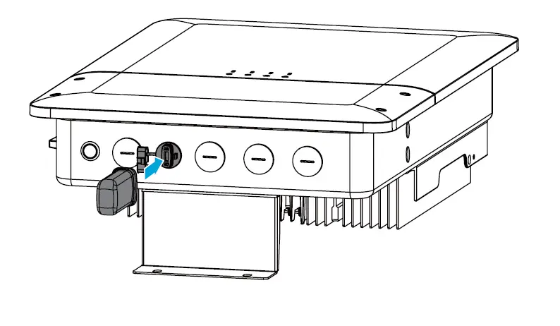
- Wi-Fi Module Port[1]
- Wi-Fi / BT Antenna Terminal[1]
- LED
- Mounting Bracket
- 4G Antenna Terminal[1]
- Heat Sink
- Mounting Plate
- Optional
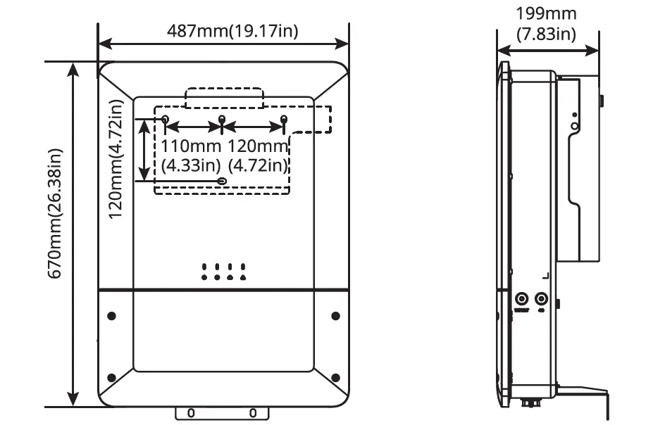
Dimensions
Inverter Installation
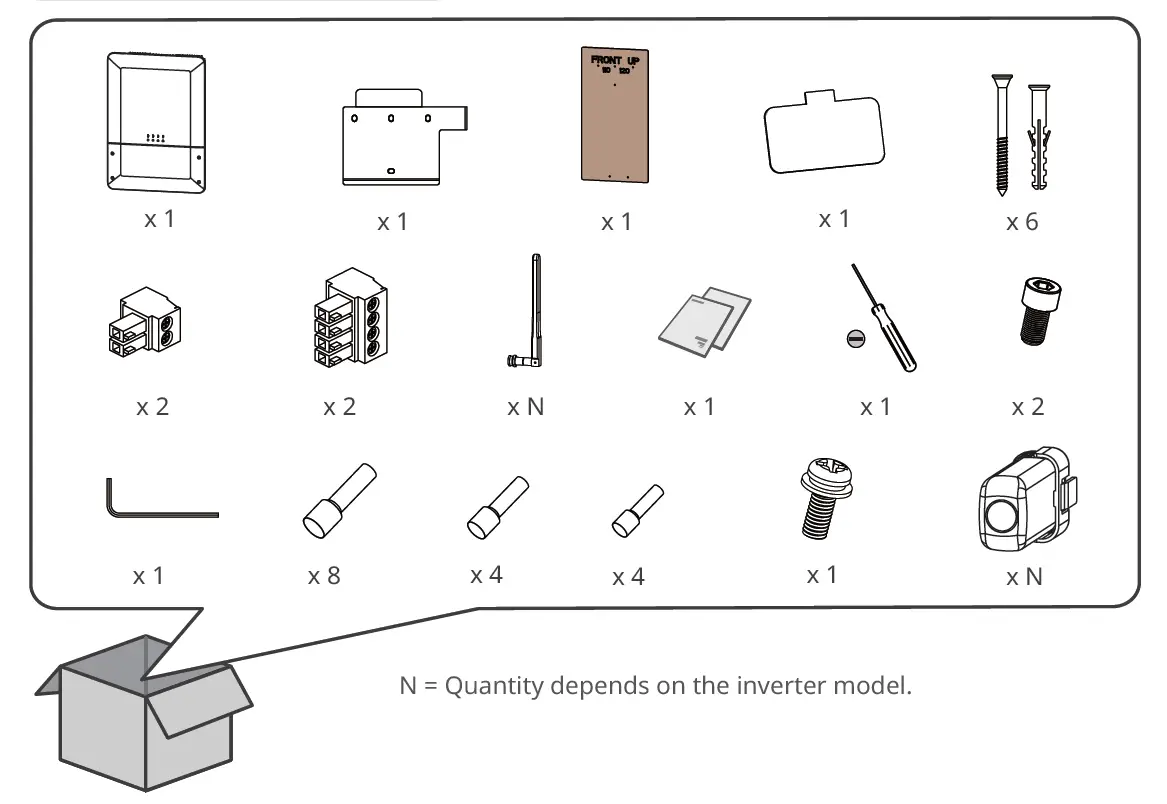
Packing List
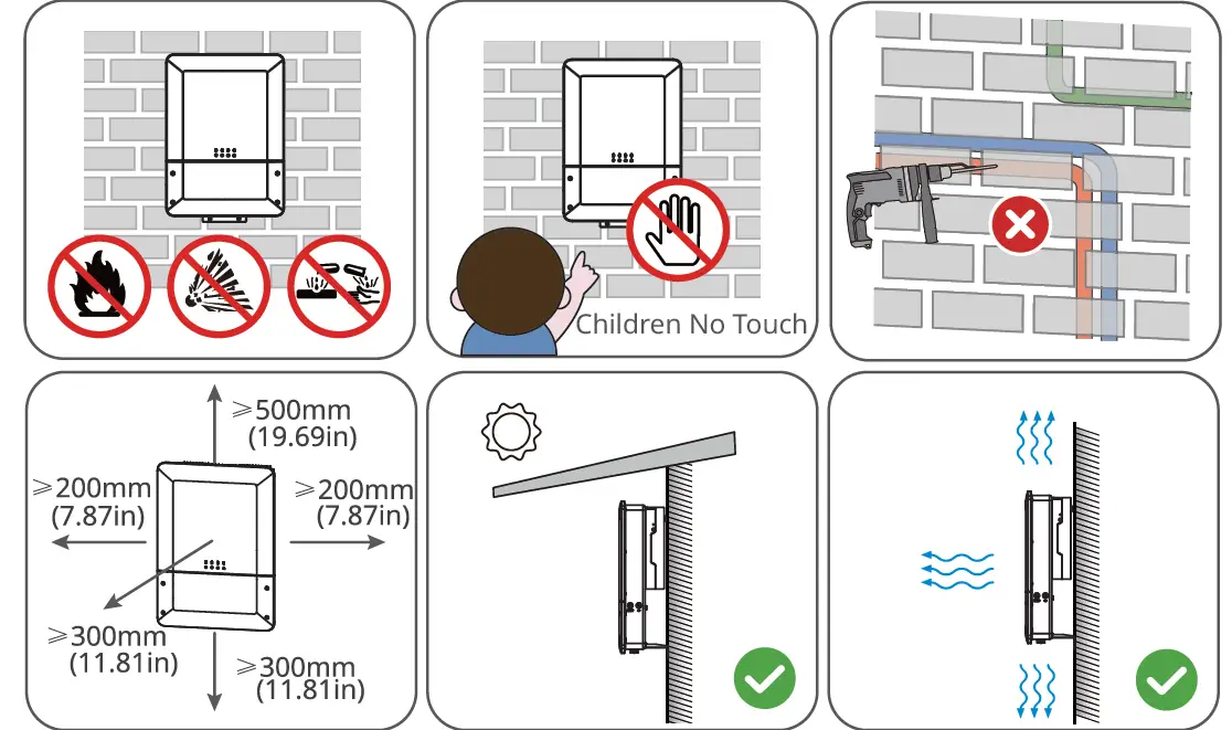
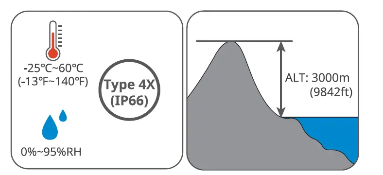
Space Requirements
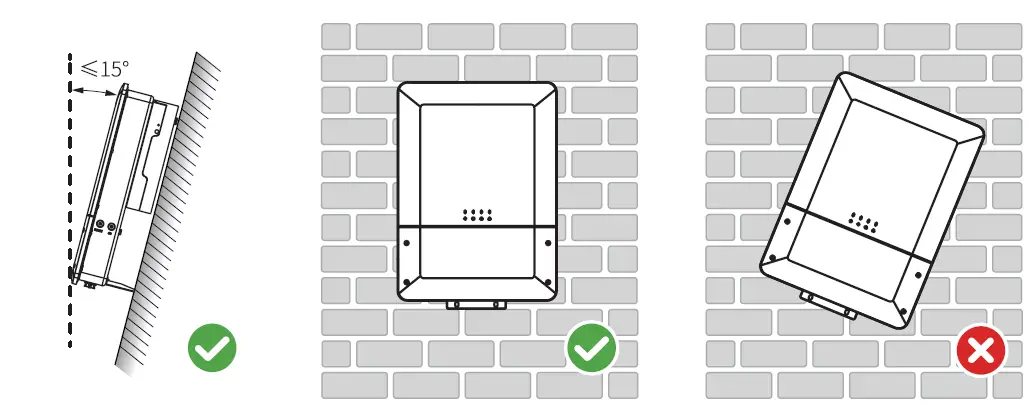
Angle Requirements
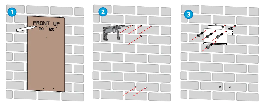
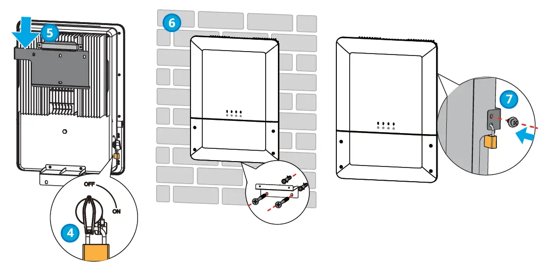
Installing the Inverter
Electrical Connection
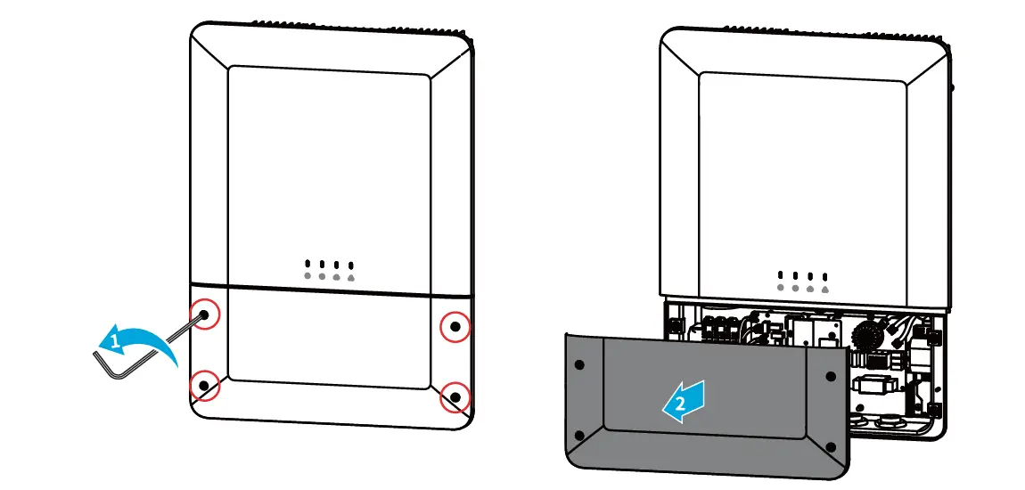
Removing the Cover
Cable Specifications
| No. | Terminal/Port | Silkscreen | Recommended Cable Specifications |
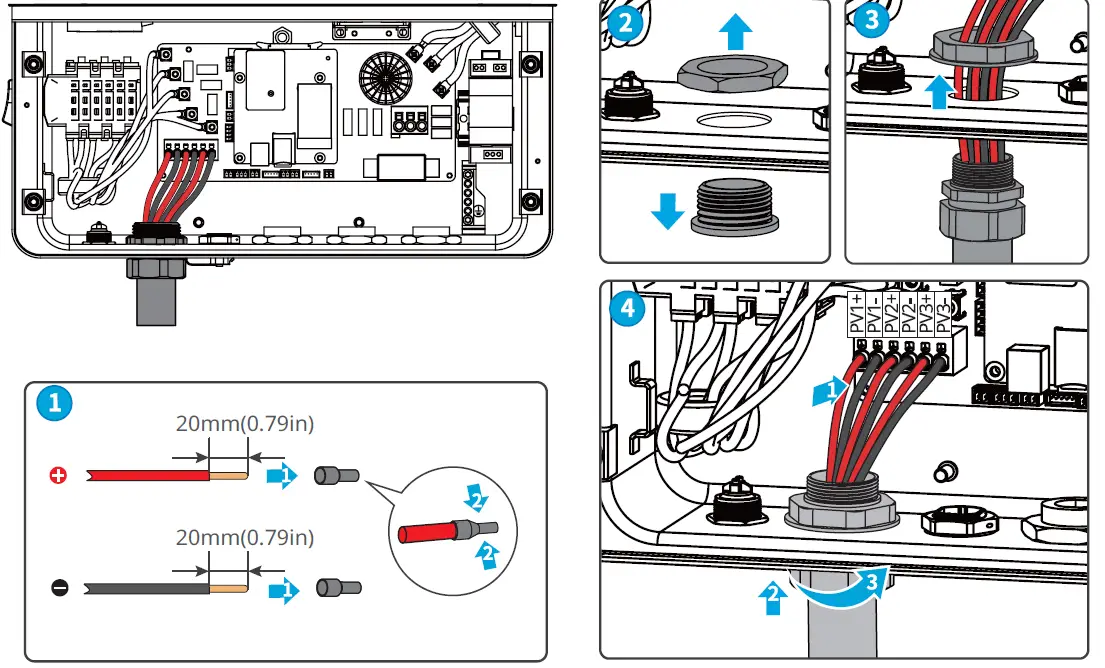
| 1 | PV input terminal | PV1+ PV1- | 90℃ (194°F) copper cables, 12AWG. |
| PV2+ PV2- | |||
| PV3+ PV3- (Only for GW7700-MS-US30, GW9600-MS-US30, GW11K4-MS-US30) | |||
| 2 | Dry contact communication terminal | DRY-OUT | – |
| 3 | CT communication terminal | CT2 | – |
| CT1 | |||
| 4 | Remote Shutdown communication terminal | DRM0 | Outdoors communication cables that meet UL2919, CM/CMG(NEC type), or CMH(CSA type) requirements, 24-16AWG. |
| 5 | Power supply terminal for RSD module | RSD-12V | Outdoors communication cables that meet UL2919, CM/CMG(NEC type), or CMH(CSA type) requirements, 24-16AWG. |
| 6 | Meter communication terminal | METER | Outdoors communication cables that meet UL2919, CM/CMG(NEC type), or CMH(CSA type) requirements, 24-16AWG. |
| 7 | Communication terminal for multi inverter parallel connection | 485-1 485-2 | Outdoors communication cables that meet UL2919, CM/CMG(NEC type), or CMH(CSA type) requirements, 24-16AWG. |
| 8 | USB port | USB | – |
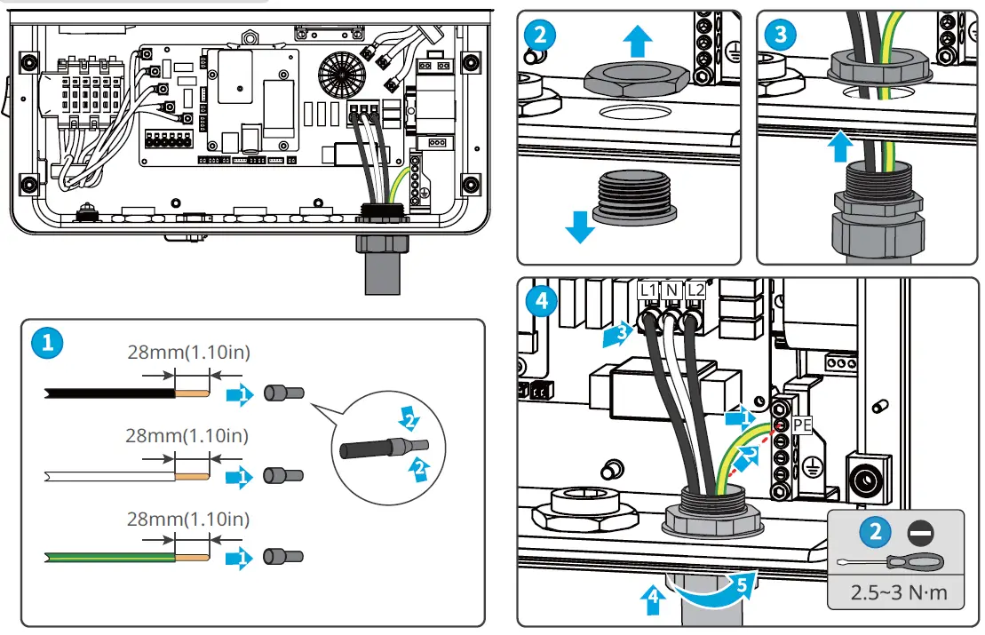
| 9 | AC cable terminal | GRID-L1 | 90℃(194°F) copper cables, 6AWG. |
| GRLD-N | |||
| GRID-L2 | |||
| 10 | Grouding busbar | – | 90℃(194°F) copper cables, 10-6AWG. |
DC Cable
AC Cable
Communication Connection
| PIN | Function | Definition |
| 1 | Remote shutdown | COM/DRM0 |
| 2 | REFGEN | |
| 3 | power supply for RSD module | 12V-AC_SPS |
| 4 | RSD-12V | |
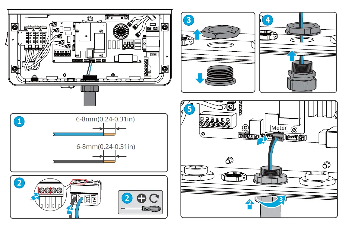
| 5 | Meter | Meter+ |
| 6 | Meter- | |
| 7 | 12V+ | |
| 8 | GND | |
| 9 | parallel connection | RS485-A |
| 10 | RS485-B | |
| 11 | RS485-A | |
| 12 | RS485-B |
The cables for remote shutdown, smart meter, parallel connection, and power supply for RSD module are connected in the same way. The following illustration shows an example of connecting smart meter communication cable.
Wi-Fi Kit (Optional)
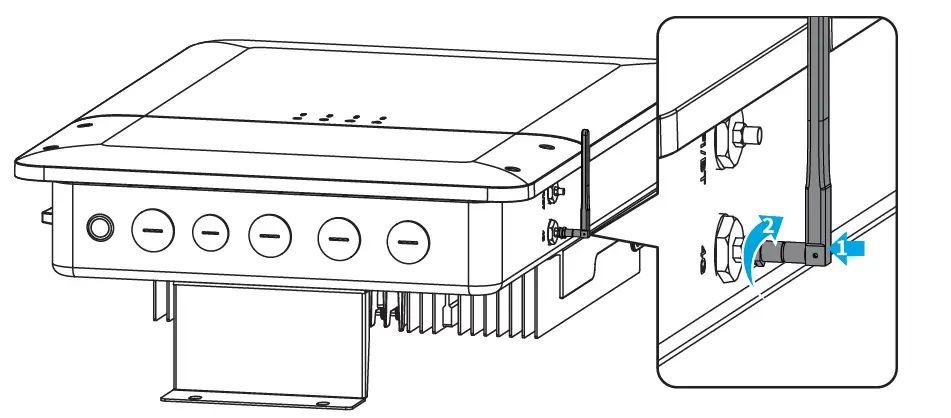
Antenna(Optional)
The 4G, Wi-Fi, and Bluetooth antenna are connected in the same way. The following illustration shows an example of installing the 4G antenna.
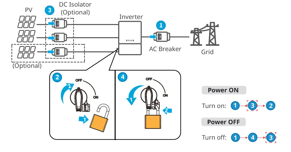
Power On and Off
Commissioning
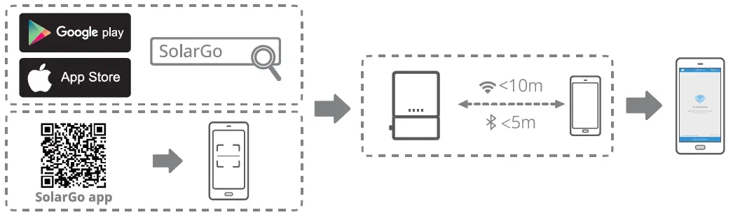
Commissioning via Solar Go APP
Monitoring via SEMS Portal App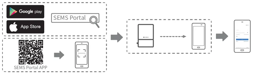
For more detailed instructions, scan the QR codes below.

MS Series 5.0-11.4kW
G3(US)
User Manual

WiFi Quick
Installation Guide

Solar Go App
User Manual

SEMS Portal
User Manual
Official Website
Good We Technologies Co., Ltd.
No. 90 Zijin Rd., New District, Suzhou, 215011, China
www.goodwe.com
[email protected]

340-00891-00

Local Contacts


