![]()
HT SERIES USER MANUAL
SOLAR INVERTER
Photovoltaic
Grid-Tie Inverter
Symbol Definition
| Safety Warning – Ignoring the warning signs in this manual may cause minor or moderate injuries. | |
| Recyclable | |
| Danger of high voltage, avoid electric shock | |
| This side shall be upside, do not tilt | |
 | Hot surface, do not touch |
 | Stacking limit, up to 4 layers can be stacked |
| The product must not be disposed of as ordinary waste, but must be recycled by special methods | |
 | Fragile items, handle with care |
| Avoid humidity | |
| See operating instructions | |
| After power off, wait 5 minutes to ensure that the machine is fully discharged | |
 | CE mark |
Safety Instructions 
Jiangsu GOODWE Power Technology Co., Ltd. (hereinafter referred to as GOODWE) HT series photovoltaic grid-tie inverters are designed and tested in strict accordance with relevant safety regulations. However, as electrical and electronic equipment, the following safety instructions must be observed during installation and maintenance, and improper operation will cause serious injury and property damage to the operator and a third party.
- The inverter must be installed and maintained by professionals in accordance with local standards and regulations.
- Before installing and maintaining the inverter, the DC input and AC grid must be disconnected from the inverter, and the inverter must not be touched for at least 5 minutes after disconnection to prevent electric shock.
- The local temperature on some parts of the inverter may exceed 60°C during operation. Do not touch it to avoid burns.
- All electrical installations must comply with local electrical standards.The inverter must only be connected to the grid by professionals and only after obtaining permission from the local power supply authority.
- The inverter must be installed in a location that is out of reach of children.
- Appropriate anti-static measures must be taken.
- Without authorization, do not remove the upper cover, and do not touch or replace other components except the wiring terminals, otherwise GOODWE will not be responsible for any personal injury or damage to the inverter.
- Ensure that the DC input voltage is less than the maximum input voltage of the inverter, otherwise the inverter will be damaged. GOODWE will not be responsible for this damage, and the warranty will be void.
- PV strings generate high-voltage direct current under sunlight. This step must be done following our company’s instructions, otherwise it may cause some protection measures to fail and endanger personal safety.
- Do not plug or unplug the DC and AC connectors when the inverter is operating.
- The IP66 requires that the machine is completely sealed. Install the machine within one day after unpacking. Otherwise, seal off the unconnected port to protect the machine against water and dust ingress.
- If the solar inverter is not to be used immediately, please ensure that the storage environment meets the following requirements:
- Do not remove the outer package;
- Recommended storage temperature: -40℃~70℃; recommended storage humidity: 0%~100% (no condensation);
- Stored in a clean and dry place and protected from dust and water vapor;
- Maximum 4 layers stacked allowed;
- Regular check is required. If any rodent bites are found, replace the packing materials immediately.
- After a long-term storage, the inverter needs to be inspected and tested by professionals before putting into use.
- During a long-term storage, the inverter has to be covered with a rainproof cloth to prevent the package from corrosion.
Product Introduction
Product Naming Rules
The models involved are as follows:
GW100K-HT
GW110K-HT
GW120K-HT
GW136K-HTH
Model Description (taking GW100K-HT as an example):
- GW – abbreviation for company name
- 100K – rated output power
- HT – model code
Product Purpose
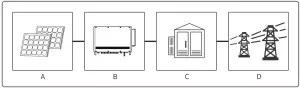
The HT series is a three-phase transformerless PV string grid-tie inverter, which is the key unit of the photovoltaic system for connecting the PV string to the grid. The inverter converts the DC power generated by the photovoltaic module into AC power that meets the parameters of the local power grid and feeds it into the power grid. The intended use of the inverter is shown in the diagram below:
![]() If an isolation transformer is not used on the output side of the inverter to connect to the power grid, neither the PV+ nor the PV- input terminal of the inverter can be connected to the ground.
If an isolation transformer is not used on the output side of the inverter to connect to the power grid, neither the PV+ nor the PV- input terminal of the inverter can be connected to the ground.
| Item | Type | Notes |
| A | PV string | Monocrystalline silicon, polycrystalline silicon, thin film PV modules without grounding |
| B | Inverter | HT series |
| C | Distribution equipment | AC distribution box |
| D | Utility grid | Different models of TN-S, TN-C, TN-C-S, TT, IT are applicable to the following grid structures |
Supported grid structure:
The grid structures supported by HT series 100K/110K/120K are TN-S, TN-C, TN-C-S, TT, IT, as shown in the figure below: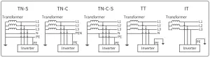
The grid structures supported by HT series 136K are TN-S, TN-C, TN-C-S, TT, IT, as shown in the diagram below: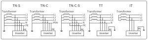 Note: For the TT grid structure, the effective value of the voltage between the neutral wire and the ground wire must be less than 20V.
Packaging information
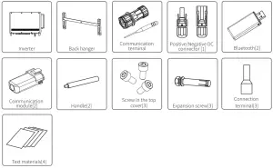
[1] DC connector*: 20 pairs for 100kw, 24 pairs for 110kw&120kw&136kw.
[2] Optional module.
[3] The number of accessories is subject to change without notice.
[4] Text materials*: Include manuals.
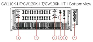
Appearance Introduction
After opening the package, check the product to confirm whether it is consistent with the specifications of the inverter you purchased. The appearance of the product is shown in the diagram. The layout of the inverter ports of different powers will differ.
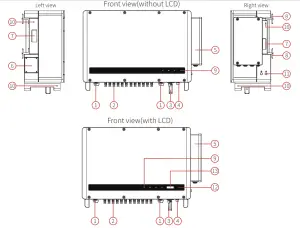
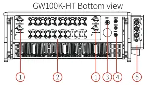
| No. | Name | Description |
| 1 | DC switch | Used to safely disconnect the DC input as required. When the input and output meet the requirements, the inverter will run automatically. Turning the DC switch to the “OFF” position will immediately cut off the DC input. You need to turn the DC switch to the “ON” position before starting the inverter. |
| 2 | DC terminal | Used to connect PV strings. |
| 3 | Communication module | Used to connect the communication module so that the inverter can use the corresponding communication method. |
| 4 | RS485 communication port | Used to connect data monitoring and other equipment. |
| 5 | AC junction box | Used to connect AC cables. |
| 6 | Fan assembly | Used to dissipate heat from the inverter and needs to be cleaned regularly. |
| 7 | Handle | Used to carry the inverter. |
| 8 | Back hanger | Used to secure the inverter on the backhanger. |
| 9 | Indicator | Display of the operating status of the inverter. |
| 10 | Lifting ring, handle mounting hole | Used to mount lifting rings and handles for inverter installation. |
| 11 | Ground port | Used to connect the ground wire to ground the inverter. |
| 12 | Button | Used to operate and configure the inverter. |
| 13 | LCD | Used to view the inverter operating parameters. |
Equipment Installation
Installation Instructions
- The installation height shall be parallel to the line of sight for easy operation and maintenance.
- The inverter must be installed away from flammable and explosive materials.
- The inverter must be installed in a place with high signal strength to ensure that there is no strong electromagnetic interference or obstructions locally.
- The parameter labels and warning signs must be clearly visible after the inverter is installed.
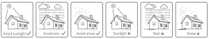
- The installation location of the inverter shall avoid sunlight, rain, and snow.
Select Installation Location
The following factors must be considered when choosing the installation location:
- The installation method and location must be suitable for the weight and size of the inverter.
- Install on a solid surface or bracket.
- The installation location must be well ventilated.
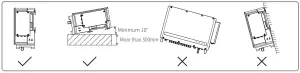
- The inclination angle of the horizontal installation shall be greater than 10°, and it is not allowed to tilt sideways. The wiring area shall face down, and the horizontal installation must be more than 500 mm above the ground. Please contact after-sales service for more information about the bracket if you need to install the mounting bracket horizontally.

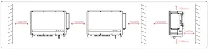
- To ensure good heat dissipation and easy disassembly, the minimum clearance around the inverter must not be less than the following values, as shown in the diagram below.

Inverter Installation
4.3.1 Wall Installation Procedure:
Step 1: Use the back hanger for positioning. Drill holes in the wall with a diameter of 13mm and a depth of 65mm. The spacing of the holes is shown in the diagram below. 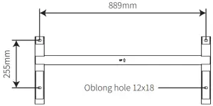
Step 2: Use the expansion screws in the accessory pack to fix the back plate on the wall.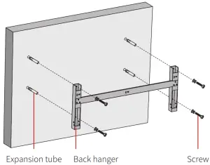
Step 3: Install handles or lifting rings on both sides of the inverter.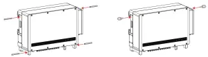
Step 4:
Method 1: Installers hold the handles and hang the inverter on the back hanger.
Method 2: Lift the machine for installation.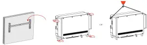 4.3.2 Bracket Installation Procedures:
Step 1: Use the back hanger for positioning. Drill holes in the wall with a diameter of 13mm and a depth of 65mm.
The spacing of the holes is shown in the diagram below.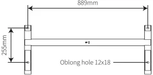 Step 2: Use the expansion screws in the accessory pack to fix the back plate on the wall.
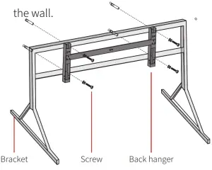
Step 3: Install handles or lifting rings on both sides of the inverter.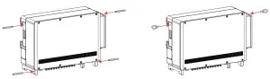
Step 4:
Method 1: Installers hold the handles and hang the inverter on the back hanger.
Method 2: Lift the machine for installation.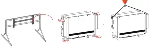
Electrical Installation
4.4.1 AC Terminal Connection
- Measure the voltage and frequency of the grid-tie connection point to confirm that it meets the grid-tie specifications of the inverter.
- It is recommended to add a circuit breaker or fuse on the AC side, whose specification shall be more than 1.25 times the rated current of the AC output.
- The PE wire (ground wire) of the inverter must be reliably grounded.
- Disconnect the circuit breaker or fuse of the inverter and the grid-tie connection point.
- It is recommended to use copper wire. If you need to use aluminium wire, consult the inverter manufacturer.
- Follow the steps below to connect the utility service and the inverter.
Note: Do not connect copper blocks with aluminum wires. Otherwise electrochemical corrosion will occur and the equipment will be damaged.
- Use copper terminals for copper wires and copper-aluminium terminals for aluminium wires.
Aluminium terminals cannot be used directly. - Please protect the stripped part with a heat shrink tube after stripping the cable.
Step 1: Select a suitable AC cable and strip the wire. For specific specifications, refer to the table below.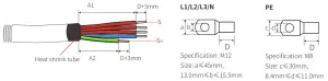
| Code | Description | Value |
| A1 | Wire Length | Approximately 500mm |
| A2 | Wire Length | Approximately 380mm |
| D | Conductor Length | Cold terminal +3mm |
| S | Cross-Sectional Area of Conductor | 70-300mm² |
| SPE | Cross-Sectional Area of Conductor | ≥S/2 |
Step 2: Connect to the communication terminal.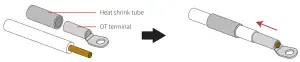
Step 3: Adjust the aperture of the crimping module.
Notice: To ensure the equipment is sealed, please adjust the aperture of the crimping module to match the cable. diameter.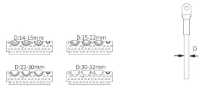
Step 4: Remove cover of the AC junction box with a M5 hex wrench.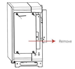 Step 5: Place half of the crimping module in the cap of the AC junction box, while the other half in the box.
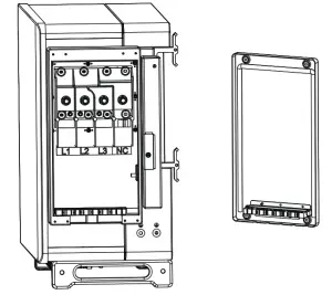
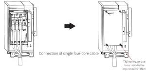
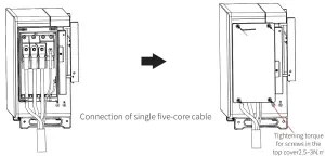
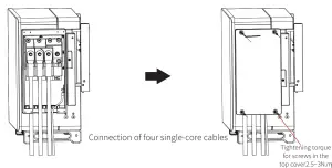
Step 6: Connect AC cables to the terminal block, and settle the AC cables to the designated crimping module.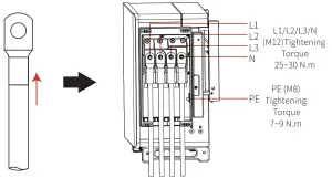
Step 7: Tighten the screws and place firefighting mud before installing the cover.
4.4.2 AC circuit breaker and leakage current protection device
To ensure that the inverter can be safely and reliably disconnected from the grid, install a circuit breaker for the inverter as a protection device.
| Inverter model | Max. Output Current (A) | Recommended circuit breaker specifications |
| GW100K-HT | 167A | 200A |
| GW110K-HT | 184A | 250A |
| GW120K-HT | 191.3A | 250A |
| GW136K-HTH | 173.2A | 225A |
Note: Multiple inverters are not allowed to share one circuit breaker.
The internal leakage current detection device of the inverter can detect the external leakage current in real time. When the leakage current exceeds the limit value, the inverter is quickly disconnected from the grid. If leakage current protection device is installed externally, the action current of a single inverter shall be 1000mA or higher.
4.4.1 DC Terminal Connection
- Ensure that the DC switch is turned off before connecting the PV string.
- Ensure that the PV string polarity matches the DC connector, otherwise the inverter will be damaged.
- Ensure that the maximum open circuit voltage of each PV string is not higher than the maximum input voltage of the inverter under any circumstances.
- The DC connector provided by our company must be used.
- The positive and negative poles of the PV string must not be connected to the PE wire (ground wire), otherwise the inverter will be damaged.
- The unused PV terminal must be reliably sealed off with waterproof plugs.
There are four types of DC connector – DEVALAN series, MC4 series, AMPHENOL H4 series, QC4.10 series.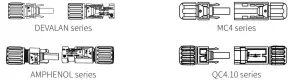 Follow the steps below to complete the DC cable connection:
Step 1: Select a suitable DC cable and strip the wire. For specific specifications, refer to the table below.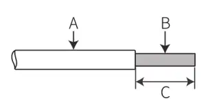
| Code | Description | Value |
| A | Wire outer diameter | 5.5~9mm |
| B | Cross- sectional area of conductor | 2.5~6mm2 |
| C | Bare wire length | Approximately 7mm |
Step 2: Take the DC terminal from the accessory pack, turn the nut to remove it, and take out the waterproof rubber ring.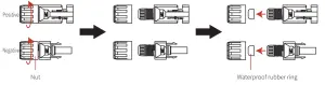
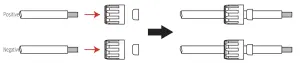
Step 3: Insert the stripped DC cable through the nut and waterproof rubber ring.
Step 4: Connect the lead part of the DC cable to the metal DC terminal and crimp it with a special DC terminal tool.
MC4 and QC4.10 series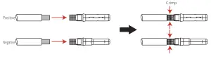 DEVALAN and AMPHENOL series
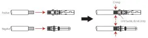 Step 5: Insert the crimped DC cable into the DC terminal, then insert the waterproof rubber ring into the DC terminal and tighten the nut.
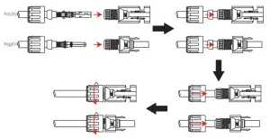 Step 6: Connect the wired DC terminals to the inverter as shown in the diagram.
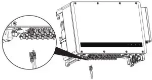
4.4.4 External Ground Terminal Connection
According to EN50178 requirements, the inverter must have a protective ground connection. The user must connect this terminal to a protective ground wire while installing the equipment. Follow the steps below to complete the ground connection.
Step 1: Select the appropriate cable and strip the outer sheath of the wire to an appropriate length. For the right length, refer to the ground terminal in the accessory pack.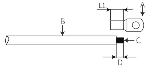
| No. | Name | Description |
| A | Ground terminal | M8 |
| B | Yellow-green line | |
| C | Cross-sectional area | |
| D | Wire length | L1+(1~2mm) |
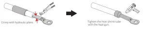
Step 2: Insert the stripped wire into the terminal, and then crimp it with pliers.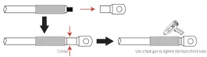
Step 3: To improve the corrosion resistance of the ground terminal after the grounding cable is installed, it is recommended to apply silica gel to the terminal as an anticorrosion treatment.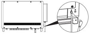
Communication Installation
4.5.1 RS485 communication
This function is only applicable to RS485 models.
The RS485 port of the inverter is used to connect to the data collector, and the total length of the connecting cable must not exceed 1000m.
The communication cable must be separated from other power lines to avoid communication interference.
The RS485 wiring method is shown in the diagram.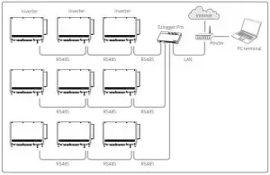
If multiple inverters are connected together and they are connected to the data logger, the maximum number of inverters connected in the daisy chain is 60.
Complete the RS485 communication connection according to the following steps.
Step 1: Take the communication terminal from the accessory pack and disassemble it as shown in the diagram.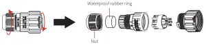 Step 2: Choose RS485 shielded twisted pair wire and strip it as shown in the diagram below, then connect the terminal and crimp it tightly.
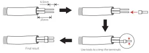
Step 3: Insert the RS485 shielded twisted pair cable through the communication terminal as shown in the diagram below, and connect it to the corresponding port according to the wiring sequence. Then assemble the terminals and tighten them.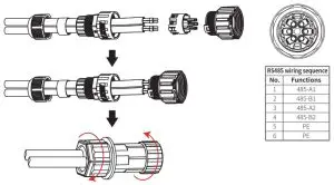
Step 4: Connect the communication terminal to the inverter COM2.
4.5.2 WiFi Communication
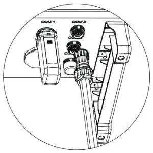
This function is only applicable to inverters with WiFi communication function. The installation method of WiFi communication module is shown in the diagram below.
Note: The communication module must be aligned and inserted vertically into the communication terminal, otherwise the communication module and communication terminal may be damaged.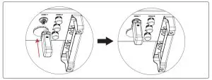
After the installation, confirm whether the indicator on the module is on. If the indicator is off, the module needs to be unplugged and installed again.
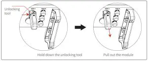
![]() To remove the module, the operator needs to use the unlocking tool supplied. The module will be damaged if this tool is not used.
To remove the module, the operator needs to use the unlocking tool supplied. The module will be damaged if this tool is not used.
Note: If the monitor is not connected, the signal strength may be too low.
4.5.3 PLC 2.0 Communication
Note:
- PLC 2.0 communication is only applicable if the output is connected to a transformer;
- PLC 2.0 communication requires SCB3000 communication box.
- Refer to the SCB3000 manual for PLC wiring methods.
4.5.4 Cloud Monitoring
After the communication configuration is completed, scan the QR code on the back of this manual or visit www.sems.com.cn. Download the goodwe.cloudview APP and complete the registration to use the cloud monitoring function.
Romote Shutdown
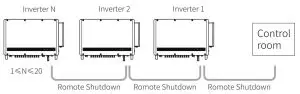
Step1:Insert the romote shutdown shielded twisted pair cable through the communication terminal as shown in the diagram below, and connect it to the corresponding port according to the wiring sequence. Then assemble the terminals and tighten them.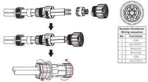
Step2:Connect the romote shutdown terminal to the inverter COM3 interface and tighten.
Operating Instructions
Indicator Description
Model without display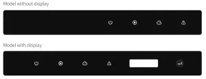
![]() Green Light
Green Light ![]() Green Light
Green Light ![]() Green Light
Green Light ![]() Red light
Red light
| Code | Status | Description |
| Long time ON: Equipment is powered on | ||
| OFF: Equipment is powered off | ||
| Long time ON: The grid is correct and the grid-tie is successful | ||
| OFF: Not grid-tied | ||
| Single slow flash: Self-check before grid-tie | ||
| Single fast flash: Grid-tie soon | ||
| Long time ON: Wireless monitoring is operating correctly | ||
| Single flash: Wireless module reset | ||
| Double flash: No base station connected | ||
| Four flashes: Server not connected | ||
| Flashing: RS485 communication is operating correctly | ||
| OFF: The wireless module is restoring factory settings | ||
| Long time ON: System error | ||
| OFF: No failure |
 Note:
Note:
For inverters without display, scan the QR code on the left to download and install the SolarGo App, and complete the corresponding configuration operations in the App.
http://www.sems.com.cn/home/solargo
Setting the country of safety regulations:
If the LCD displays “GW100K-HT Power = XXXXX watts”, press and hold for 2s to enter the first level menu “China’s max voltage”. In the second level menu, select the appropriate safety regulation country according to the installation location, and wait 10s after selecting the country.
The machine will display “Setting up…”. Complete the setup, then a message will appear: “Setting is completed successfully” or “Setup failed”.
- The display screen is shown on the right Grid-tie power generation
Power = XXXXX watts - The description of the display area is as shown on the right
 1st row: Display bar of status information:
*The first row shows the status information of the system. Display of “Waiting for power generation power = 0 watts” means the inverter is in standby state;
Display of “Detection timing **sec power = 0 watts” indicates that the inverter is self-checking and preparing to generate electricity; Display of “grid-tie power generationpower =XXXXX watts”means that the inverter is in power generation state; when an abnormal state occurs in the system, an error message will be displayed. For details, refer to the *5.3 Failure Information* table.
*The operating parameters of the system can be switched and displayed in the status bar by pressing the buttons. There are two levels of menus for the buttons. The specific switching of contents and its procedure can be seen in the right diagram:
*The menu display is controlled using the buttons. Long press the button to enter the submenu 2nd row: This area displays the real-time power generation of the inverter - Button Description
The buttons are categorized into two operations: Short press and long press - Details of buttons and LCD screen:
*The basic functions can be set by pressing the buttons, such as time, language, safety regulation country, etc., and the data can also be checked by pressing the buttons.
*The LCD screen status display area is divided into two levels of menus. In some of first level menus, second level menus can be entered into by long pressing the buttons; If there is no second-level menu, press and hold for 2 seconds to lock the current display interface.
*In all menus, the system will automatically revert to the first item of the first level menu after 20 seconds if no button is operated. - Menu Introduction
*After the machine is powered on, the default display is the first level menu.
*The status display is the first menu of the first level menu, which displays the current status of the machine: The initial state of power-on shows “Waiting for power generation”. If it enters the power generation state, it displays the “Grid-tie power generation”. If the machine is faulty, the failure information is displayed
*Short press the button once to enter the input voltage display menu, which is used to display the PV voltage in “V”.
*Short press the button once to enter the input current display menu, which is used to display the PV current in “A”.
*Short press the button once to enter the utility voltage display menu, which is used to display the mains voltage in “V”.
*Short press the button once to enter the output current display menu, which is used to display the output current in “A”.
*Short press the button once to enter the utility frequency display menu, which is used to display the mains frequency in “Hertz”.
*Check failure code Short press the button once to enter the failure history display menu, which is used to display the fault information of the machine, and long press for 2 seconds to enter the second level menu to view the five latest fault messages: Error message, failure time (190520 15: 00). To exit the second-level menu, do not press the button for 20 seconds. The display backlight will go off, and the machine will automatically return to the status display menu of the first-level menu.
*Check model
Short press the button once to enter the “Model Name” display menu and display the model name.
*Check software version Short press the button once to enter the software version display menu, which is used to display the current software version number such as: “Software version: V1.XX.XX.XX”. If you do not press the button for 20 sec., the backlight of the display will go off and the machine will automatically return to the state display menu of the first level menu.
*Time setting Short press the button once to enter the system time setting menu, which is used to set the current time of the machine, and enter the second level menu by long pressing the button for 2 seconds:
“2000-00-00 00:00”, the first and second digits remain unchanged by default. The third and fourth digits are used to set the year (setting range 2000~2099). The fifth and sixth digits are used to set the month. The seventh and eighth digits are used to set the date. The ninth and tenth digits are used to set the hours, the eleventh and twelfth digits to set the minutes. Each digit is set by short pressing the button. To switch to the next digit, long press for 2 seconds. If you entered the second level screen without making any changes, and did not press the button within 20 seconds, the display backlight will go off and you will automatically return to the status display menu of the first level menu. If you make changes, enter the “Setting up…” screen, then it will display “Setting is completed successfully” or “Setup failed”. Finally, the machine will automatically return to the status display menu of the first level menu.
*Set shadow MPPT function.
Short press the button once to enter the shadow MPPT function menu, long press for 2 seconds to turn the shadow MPPT function on or off.
Display of “Shadow mode OFF Power =XXXXX watts” indicates the Off state. Display of “Shadow mode ON Power =XXXXX watts” indicates the On state. - Normal power-on and display on operation screen
*When the input voltage is greater than the turn-on voltage, the machine starts to run, and the yellow light comes on first. After a few seconds, the screen starts to display the following information:
“Grid loss Power =XXXXX watts”. If there is utility power at this time, it will display
“Detection timing **sec power = 0 watts”. At this time, ** seconds are decremented. When the number is reduced to 0, the relay action will be heard, and then “grid-tie power generation” will be displayed, and the current machine power will be displayed in the second row.
 1st row: Display bar of status information:
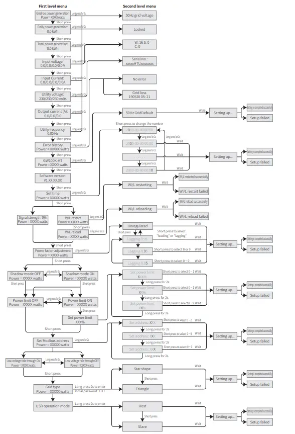
Failure Information
The error message in the following table will be displayed on the screen when the abnormal situation occurs:
| Error Message | Description |
| SPI Comm Fail | Internal Communication Failure |
| EEPROM Fail | EEPROM R/W Failure |
| Fac Fail | Fac Failure |
| Relay Fail | Relay Check Failure |
| PV** over Curr | PV** hardware current over range |
| DCI High | DC Injection High |
| Isolation Fail | Isolation Failure |
| Vac Fail | Vac Failure |
| ExFan Fail | External Fan Failure |
| PV Over Voltage | PV Over Voltage |
| Over Temperature | Over Temperature |
| InFan Fail | Internal Fan Failure |
| DC Bus High | DC Bus High |
| Gnd I Fail | Ground I Failure |
| Utility Loss | Utility Loss |
| Ref-V Chek Fail | Reference Voltage Check Failure |
| GFCI Failure | GFCI Device Failure |
Frequently Asked Questions
Under normal conditions, the inverter requires no maintenance. If the inverter cannot work normally, refer to the following instructions:
When a problem occurs, the red light on the operation panel will light up, and relevant information will be displayed on the APP. See the table below for details, and the content in brackets provides the interpretation.
| Type | Display | Troubleshooting |
| System error | Isolation Failure | 1. Disconnect the DC switch, remove the DC connector, and measure the impedance between the positive and negative poles of the DC connector and the ground. 2. If the impedance is lower than 100 kilohms, check the insulation of the PV string wiring to the earth. 3. If the impedance is higher than 100 kilohms, call the local service department. 4. Remove the AC connector and measure the impedance of the N wire to the ground wire. If higher than 10 ohms, check the AC wiring. |
Ground I Failure | 1. Disconnect the DC switch and check the insulation of the PV string to the earth. 2. After the check is completed, close the DC switch. 3. If the problem persists, call the local service department. | |
Vac Failure | 1. Disconnect the AC Breaker, remove the AC connector, measure the voltage between the live wire and the neutral wire in the connector, and confirm whether it matches the grid-tie specifications of the inverter. 2. If it does not match, check the network cable wiring. 3. If it matches, connect the AC connector and close the AC Breaker. The inverter will automatically resume grid-tie. If the problem persists, call the local service department. | |
Fac Failure | 1. If the grid frequency returns to normal state, the inverter will automatically resume grid-tie. 2. If the problem persists, call the local service department. | |
Utility Loss | 1. Disconnect the AC Breaker, remove the AC connector, measure the voltage between the live wire and the neutral wire in the connector, and confirm whether it matches the grid-tie specifications of the inverter. 2. If not, check whether the power distribution switch is closed and whether the power supply is operating correctly. 3. If it matches, connect the AC connector and close the AC Breaker; if the problem persists, call the local service department. | |
PV Over Voltage | 1. Disconnect the DC switch, remove the DC connector, and measure the PV stringvoltage. Confirm whether it exceeds the inverter input voltage specification. 2. If yes, reconfigure the PV string. 3. If not and the problem persists, call the local service department. |
| Type | Display | Troubleshooting |
| Inverter failure | Relay Check Failure | 1. Disconnect the DC switch. 2. Close the DC switch again. 3. If the fault occurs again, call the local service department. |
| DC Injection High | ||
| EEPROM R/W Failure | ||
| Internal Communication Failure | ||
| DC Bus High | ||
| GFCI Device Check Failure | ||
| Other Failures | No display (Indicator and display are not lit) | 1. Disconnect the DC switch, remove the DC connector, and measure the PV string voltage. 2. Insert the DC connector, and then close the DC switch. 3. If the voltage is lower than 200V, check the PV string configuration. 4.1f the voltage is higher than 200V and there is still no display, call the local service department. |
Note: When the sunlight is insufficient, the photovoltaic inverter may start up frequently. This is caused by insufficient PV string power and will not cause damage to the inverter.
Technical Data
Product Specifications
| Technical Data | GW100K-HT | GW110K-HT | GW120K-HT | GW136K-HTH |
| DC input parameters | ||||
| Maximum DC input power (kW) | 150 | 165 | 180 | 205 |
| Maximum DC input voltage (V) | 1100 | 1100 | 1100 | 1100 |
| MPPT operating voltage range (V) | 180∼1000 | 180∼1000 | 180∼1000 | 180∼1000 |
| Minimum start-up voltage (V) | 200 | 200 | 200 | 200 |
| Rated input voltage (V) | 600 | 600 | 600 | 750 |
| Maximum input current (A) | 10*30 | 12*30 | 12*30 | 12*30 |
| Maximum short-circuit current (A) | 10*45 | 12*45 | 12*45 | 12*45 |
| No. of MPP Trackers | 10 | 12 | 12 | 12 |
| No. of Input Strings per Tracker | 2 | 2 | 2 | 2 |
| AC output data | ||||
| Rated output power (kW) | 100 | 110 | 120 | 136 |
| Maximum output power (kW) | 110 | 121 | 132 | 150 |
| Maximum apparent power (kVA) | 110 | 121 | 132 | 150 |
| Rated output voltage (V) | 400, 3L/N/PE or 3L/PE | 400, 3L/N/PE or 3L/PE | 400, 3L/N/PE or 3L/PE | 500, 3L/PE |
| Output frequency (Hz) | 50/60 | 50/60 | 50/60 | 50/60 |
| Maximum output current (A) | 167 | 175.5 | 191.3 | 173.2 |
| Power factor | ~1 (0.8 leading……0.8 lagging adjustable) | |||
| Output THDi (@rated output) | <3% | <3% | <3% | <3% |
| Efficiency | ||||
| Maximum conversion efficiency | 98.6% | 99.0% | ||
| European efficiency | 98.3% | 98.5% | ||
| Protection | ||||
| String current monitoring | Integrated | |||
| Internal humidity detection | Integrated | |||
| Residual current monitoring | Integrated | |||
| Insulation resistance detection | Integrated | |||
| Anti-islanding protection | Integrated | |||
| Input reverse protection | Integrated | |||
| DC surge protection | Type II (Type I optional) | |||
| AC surge protection | Type II (Type I optional) | |||
| Output overcurrent protection | Integrated | |||
| Output short circuit protection | Integrated | |||
| Output overvoltage protection | Integrated | |||
| AFCI DC arc protection | Optional | |||
| PID recovery | Optional | |||
| AC terminal overtemperature protection | Optional | |||
| Emergency quick shutdown | Optional | |||
| General Data | ||||
| Operating temperature (℃) | -30~60 | |||
| Relative humidity | 0~100% | |||
| Operating altitude (m) | ≤4000 | |||
| Cooling method | Intelligent forced air cooling | |||
| Interface | LED (Standard), LCD (Optional), Bluetooth+APP | |||
| Communication | RS485 or PLC or WiFi | |||
| Weight (kg) | 93.5 | 98.5 | 98.5 | 98.5 |
| Dimensions (width x height x thickness mm) | 1005*676*340 | |||
| Degree of protection | IP66 | |||
| Night loss (W) | <2 | |||
| Topology | Transformerless | |||
| Certification & Standards | ||||
| Grid-tie standard | ||||
| Safety standard | ||||
| EMC standard | ||||
Interpretation of overvoltage levels:
Overvoltage level I: Connect the product to a circuit with measures to limit instantaneous overvoltage to a relatively low level.
Overvoltage level II:
Energy-consuming equipment powered by fixed power distribution devices. Such equipment includes appliances, portable tools and other household and similar loads. If there are special requirements for the reliability and applicability of such equipment, overvoltage level III shall be adopted.
Overvoltage level III:
The reliability and applicability of equipment in fixed power distribution installations must meet special requirements, including switching appliances in fixed power distribution devices and industrial equipment permanently connected to fixed power distribution devices. Overvoltage level IV: The equipment used in the power supply of the power distribution device, including measuring instruments and prepositioned overcurrent protection equipment, etc.
Interpretation of humid places
| Environmental Parameters | Level | ||
| 3K3 | 4K2 | 4K4H | |
| Temperature range | 0°C~+40℃ | -33°C~+40℃ | -20°C~+55℃ |
| Humidity range | 5% to 85% | 15% to 100% | 4% to 100% |
Interpretation of environmental levels:
Outdoor inverter: The ambient air temperature range is -25°C~+60℃, suitable for pollution level 3 environment;
Indoor type II inverter: The ambient air temperature range is -25°C~+40℃, suitable for pollution level 3 environment;
Indoor type I inverter: The ambient air temperature range is 0°C~+40℃, suitable for pollution level 2 environment;
Interpretation of pollution levels
Pollution level 1: No pollution or only dry non-conductive pollution;
Pollution level 2: Usually there is only non-conductive pollution, but there may be temporary conductive pollution caused by condensation;
Pollution level 3: There is conductive pollution, or non-conductive pollution becomes conductive pollution due to condensation;
Pollution level 4: There is persistent conductive pollution, such as pollution caused by conductive dust or rain and snow.
Schematic Diagram of Main Circuit
The main circuit of GW100K-HT is shown in the following diagram: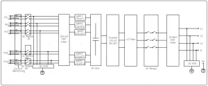 The main circuit of GW110K-HT/GW120K-HT is shown in the following diagram:
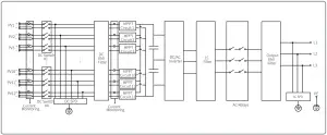
The main circuit of GW136K-HTH is shown in the following diagram: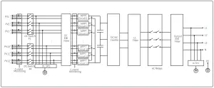
Product Maintenance
Regular maintenance of the inverter will ensure its service life and best efficiency.
Note: Before carrying out any maintenance, turn off the AC circuit breaker, disconnect the DC circuit breaker, and wait 5 minutes until the residual voltage is released.
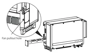
Clean Fan
The external fan of the HT series inverter needs to be cleaned with a vacuum cleaner every year. Remove the fan and give it a thorough clean.
- Turn off the AC circuit breaker first, and then turn off the DC switch;
- Wait 5 minutes until the residual voltage is released and the fan stops running;
- Remove the fan net;
Use a screwdriver to loosen the fan bracket Carefully disassemble the fan net and fan (because the internal circuit of the fan is still connected, do not pull out a single fan) as shown in the diagram below; - Use a soft brush, cloth or compressed air for cleaning; tighten the screws.
DC Switch Check
In normal use, the DC switch requires no maintenance.
Although not strictly necessary, we still recommend you to:
• check the DC switch regularly:
• turn the DC switch on and off 10 times a year.
Operating the switch regularly can clean up the device and extend its service life.
Note: Turn off the AC breaker first, and then turn off the DC switch.
Startup sequence
- Turn the circuit breaker on the AC side to the “ON” position;
- Turn the DC switch of the inverter to the “ON” position.
Shutdown sequence
- Turn the circuit breaker on the AC side to the “OFF” position;
- Turn the DC switch of the inverter to the “OFF” position.
![]() If the startup and shutdown sequences given above are not followed strictly, the inverter may be damaged.
If the startup and shutdown sequences given above are not followed strictly, the inverter may be damaged.
Electrical Connection Check
- Check whether the cable connection is loose;
- Check whether the grounding cable is reliably grounded;
- Check whether the waterproof covers for RS485, WiFi and other ports are sealed correctly.
Note: The maintenance cycle is once every six months.
 http://www.sems.com.cn/home/solargo http://www.sems.com.cn/home/solargo |  https://www.semsportal.com/home/AppDownload https://www.semsportal.com/home/AppDownload |  https://www.semsportal.com https://www.semsportal.com |  https://en.goodwe.com/ https://en.goodwe.com/ |
 340-00432-02
| GOODWE (Germany) Fürstenrieder Str. 279a 81377 München, Germany T: +49 8974120210 +49 421 83570-170 (service) [email protected] [email protected] | GOODWE (Brazil) Rua Abelardo 45, Recife/PE, 52050-310 T: +55 81 991239286 [email protected] [email protected] |
| GOODWE (Netherlands) Franciscusdreef 42C, 3565AC Utrecht, the Netherlands T: +31 (0) 30 737 1140 [email protected] [email protected] | GOODWE (UK) 6 Dunhams Court, Dunhams Lane, Letchworth Garden City, SG6 1WB UK T:+ 44 (0) 333 358 3184 [email protected] / [email protected] |
| GOODWE (India) 1202, G-Square Business Park, Sector 30A, Opp. Sanpada Railway Stn., Vashi, Navi Mumbai- 400703 T: +91 (0) 2249746788 [email protected] / [email protected] | GOODWE (Italy) Via Cesare Braico 61, 72100 Brindisi, Italy T: +39 338 879 38 81; +39 831 162 35 52 [email protected] (sales) [email protected]; [email protected] (service) |
| GOODWE (Turkey) Adalet Mah. Megapol Tower K: 9 No: 110 Bayraklı – Izmir T: +90 (232) 935 68 18 [email protected] [email protected] | GOODWE (Australia) Level 14, 380 St. Kilda Road, Melbourne, Victoria, 3004, Australia T: +61 (0) 3 9918 3905 [email protected] / [email protected] |
| GOODWE (Mexico) Oswaldo Sanchez Norte 3615, Col. Hidalgo, Monterrey, Nuevo Leon, Mexico, C.P. 64290 T: +52 1 81 2871 2871 [email protected] / [email protected] | GOODWE (Korea) 8F Invest Korea Plaza, 7 Heoleung-ro Seocho-gu Seoul Korea (06792) T: 82 (2) 3497 1066 [email protected] / [email protected] |
| GOODWE (China) No. 90 Zijin Rd., New District, Suzhou, 215011, China T: +86 (0) 512 6958 2201 [email protected] (sales)/[email protected] (service) |
Note: The above contact information is subject to change without notice. For details, refer to the company’s official website www.goodwe.com ![]()


