![]() Quick Installation Guide
Quick Installation Guide
PV Grid-Connected Inverter
SG25CX-P2 / SG30CX-P2 / SG33CX-P2 /
SG36CX-P2 / SG40CX-P2 / SG50CX-P2
SG Series PV Grid Connected Inverter
- Contents may be periodically updated or revised due to product development. The information in this guide is subject to change without notice. In no case shall this guide substitute for the user manual or related notes on the device.
- Make sure to read over, fully understand and strictly follow the detailed instructions of the user manual and other related regulations. Visit http://www.sungrowpower.com/, choose “PV Inverters” and search for the device model on the “Products” tab page to view or obtain the user manual.
- All operations can be performed only by qualified personnel, that must be trained in the installation and commissioning of the electrical system, as well as the dealing with hazards, and should also have the knowledge of the manual and of the local regulations and directives.
- Before installation, check that the package contents are intact and complete against the packing list. Contact SUNGROW or the distributor in case of any damaged or missing components.
- The cable must be intact and well insulated. Operation personnel must wear proper personal protective equipment (PPE) all the time.
- Any violation to the instructions in this quick installation manual or the operation manual could result in personal death or injury or device damage, and will void the warranty.
Safety
Please follow the safety instructions related to the PV strings and the utility grid. Otherwise, SUNGROW shall not be held liable for any damage caused.![]() DANGER
DANGER
Lethal voltage!
- PV strings will produce electrical power when exposed to sunlight and can cause a lethal voltage and an electric shock
- Only qualified personnel can perform the wiring of the PV panels.
- All electrical connections must be in accordance with local and national standards.
- Only with the permission of the utility grid, the inverter can be connected to the utility grid.
- Do not open the enclosure at any time. Unauthorized opening will void guarantee and warranty claims and in most cases terminate the operating license.
- When the enclosure lid is removed, live components can be touched which can result in death or serious injury due to electric shock.
![]() WARNING All the warning labels and nameplate on the inverter body must be clearly visible and not be removed, covered or pasted.
WARNING All the warning labels and nameplate on the inverter body must be clearly visible and not be removed, covered or pasted.![]() CAUTION Risk of bums due to hot components! Do not touch any hot parts (such as heat sinks) during operation. Only the DC switch can safely be touched at any time.
CAUTION Risk of bums due to hot components! Do not touch any hot parts (such as heat sinks) during operation. Only the DC switch can safely be touched at any time.![]() NOTICE Only qualified personnel can perform the country setting. Unauthorized alteration of the country setting may cause a breach of the type-certificate marking.
NOTICE Only qualified personnel can perform the country setting. Unauthorized alteration of the country setting may cause a breach of the type-certificate marking.
The symbols on the inverter body are as follows.
The height of the label should not exceed 5mm. | |
 CE mark of conformity. EU/EEA Importer. CE mark of conformity. EU/EEA Importer. | |
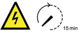 Danger to life due to high voltages! Danger to life due to high voltages!Do not touch live parts for 15 minutes after disconnection from the power sources. Only qualified personnel can open and maintain the inverter. | |
 Check the user manual before service! Check the user manual before service! | |
Scope of Delivery
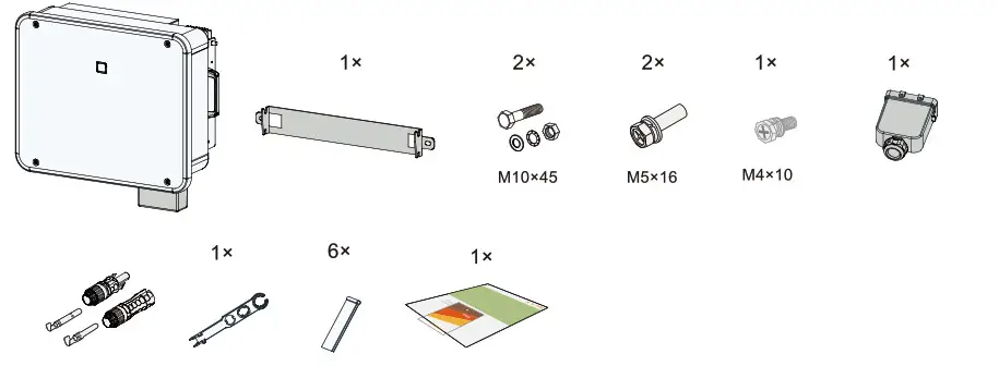
* The images shown here are for reference. The actual product and quantity are based on delivery.
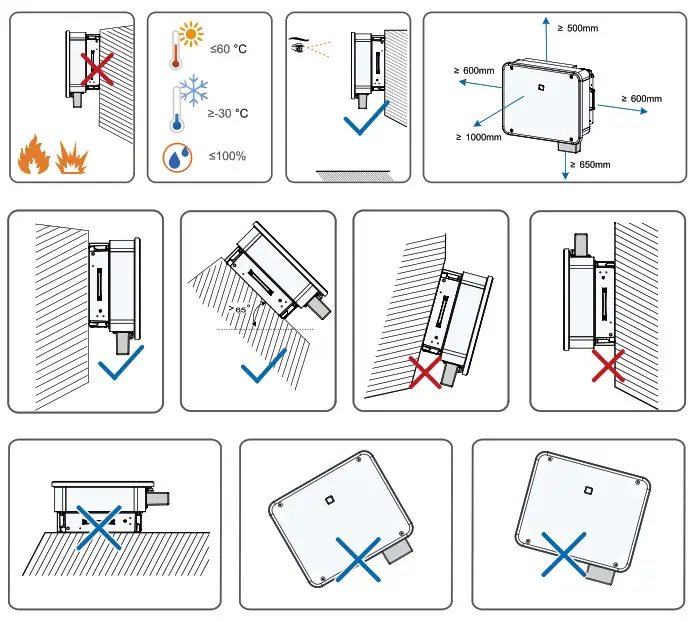
Mounting location
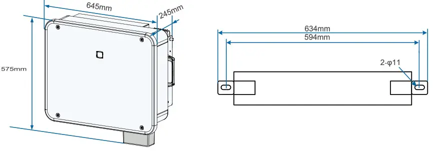
Dimension
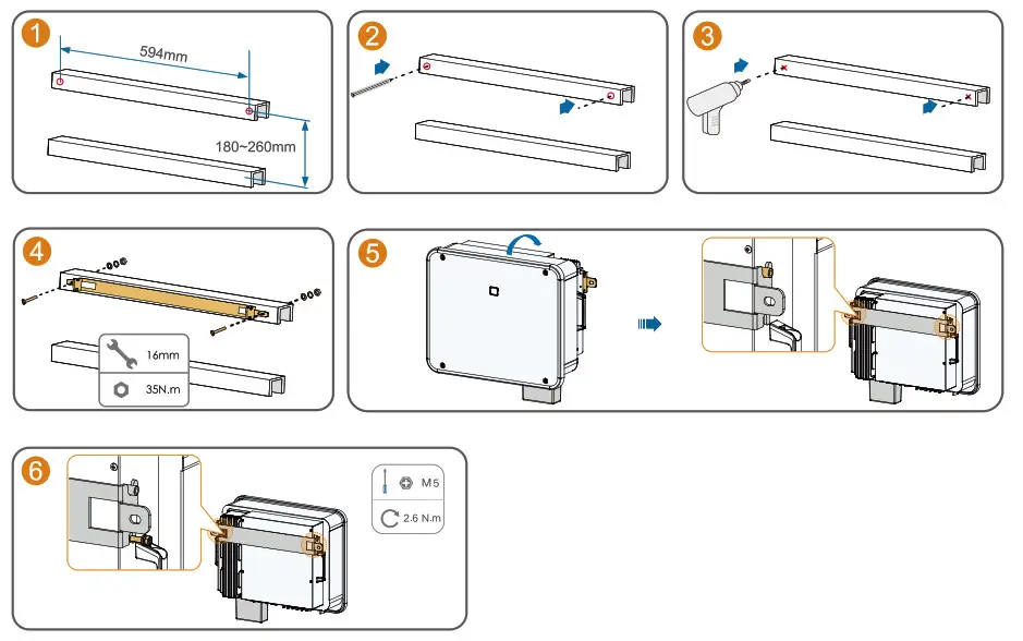
Mounting
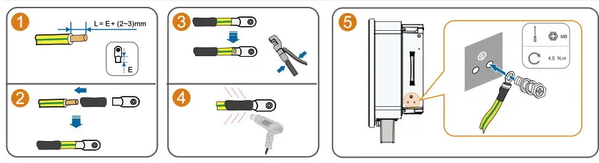
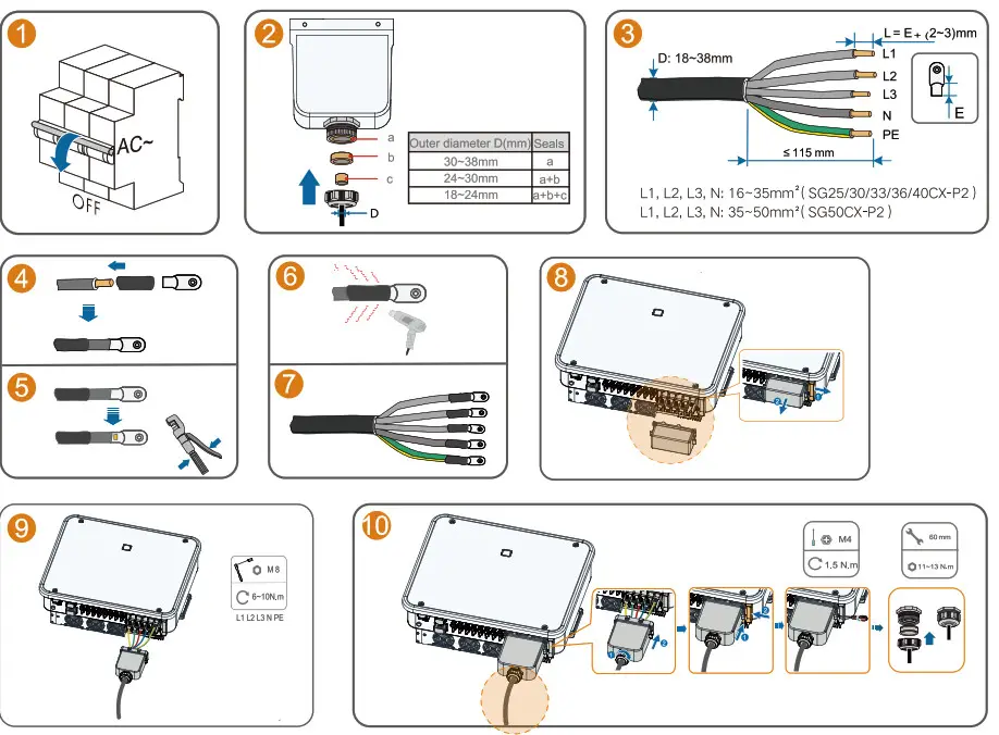
PE Connection
AC Connection (For a multi-core cable)
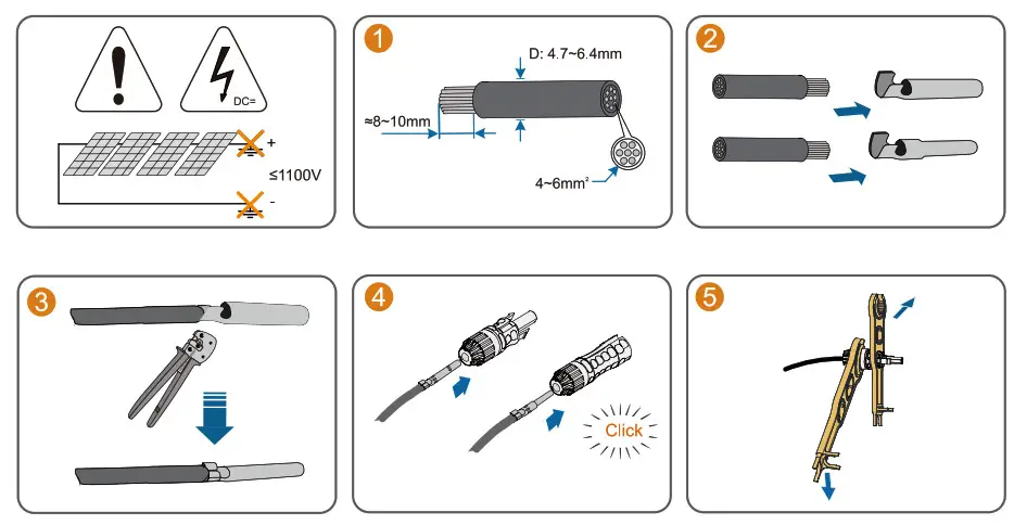
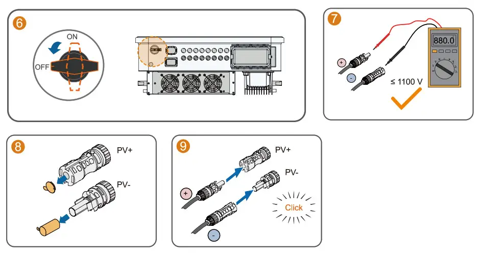
DC Connection
Communication Module Connection (optional)
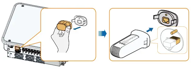
The image shown here is for reference only. The ac tual product you receive may differ.
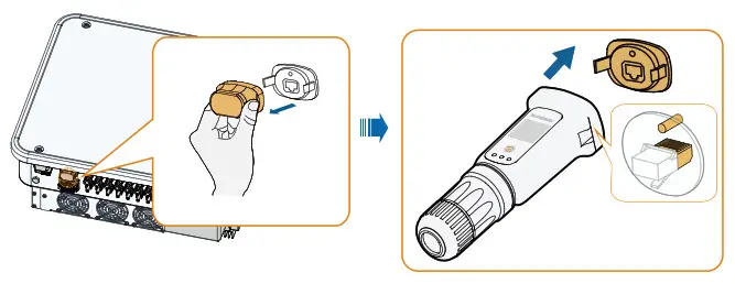
WinEst-S Connection (optional)
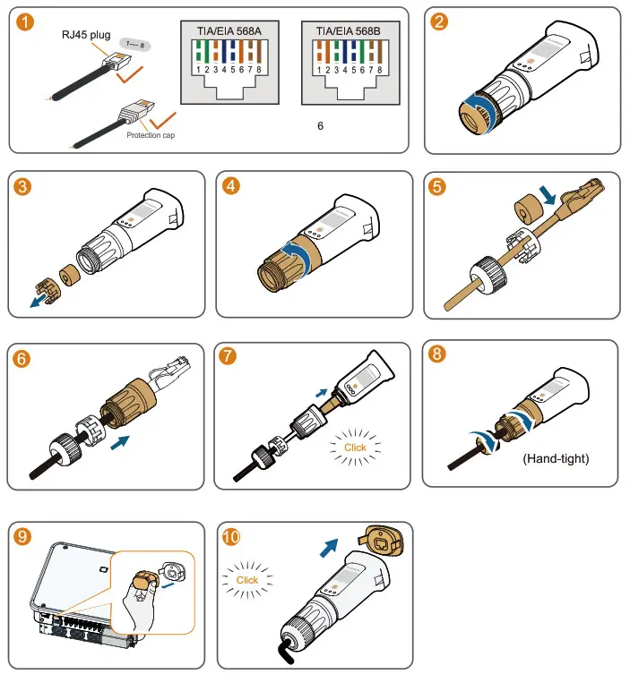
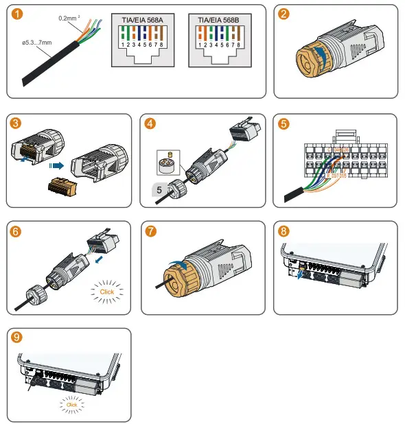
Installation with WLAN communication
Installation with Ethernet communication
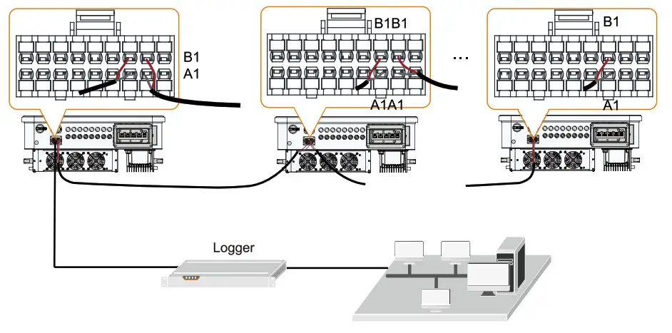
COM2 (DI, DRM, DO, RS485,Met
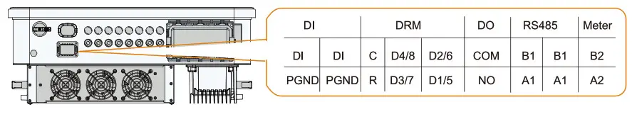
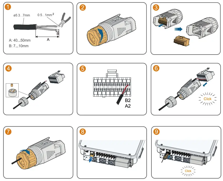
COM2 Connection (DI, DO, RS485, Meter)
Inverter parallel
Maximum 30 hybrid inverters with the same type can be connected i n parallel.
COM2 Connection (DRM)\
The images shown here are for reference only. The actual product received shall prevail.
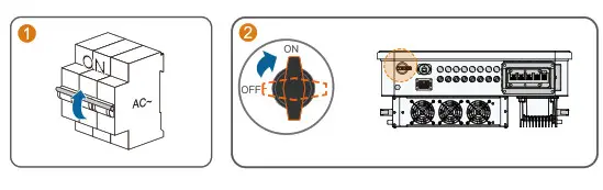
Power on
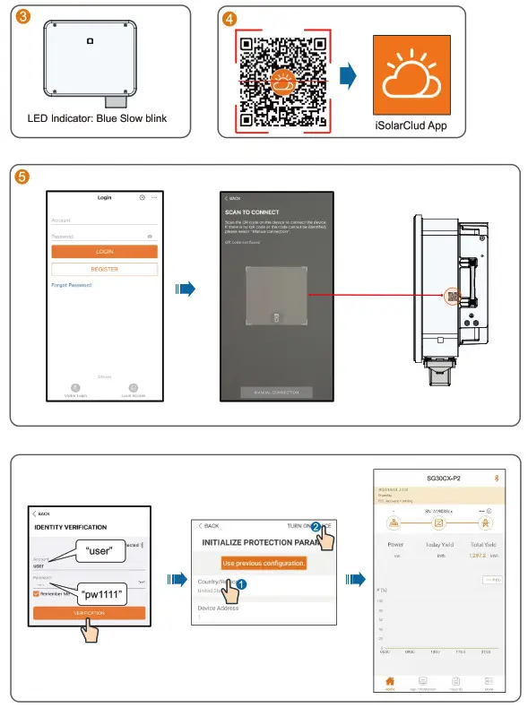
LED Indicator
| LED color | State | Definition |
 | ON | The device is connected to the grid and operating normally. |
| Fast blink (Period: 0.2s) | The Bluetooth communication is connected and there is data communication. No system fault occurs. | |
| Slow blink (Period: 2s) | The device is in standby or startup state (not feeding power into the grid). | |
| Slow blink once, fast blink three times | The inverter is performing PID recovery. | |
 | ON | A fault occurs and the device cannot connect to the grid. |
| Twinkling | The Bluetooth connection is established, data communication in process, and a system fault occurs. | |
, | OFF | Both the AC and DC sides are powered down. |
 More information i n the QR code or
at http://support.sungrowpower.com/
![]() Sunglow Power Supply Co., Lid.
Sunglow Power Supply Co., Lid.
www.sungrowpower.com  QIEN M-H-002507


