![]() SOLAR INVERTER SVN
SOLAR INVERTER SVN
(15 kVA)
ON-Grid Charger
3-Phase
User Manual
Introduction
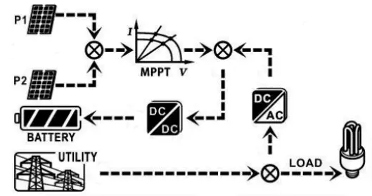
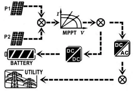
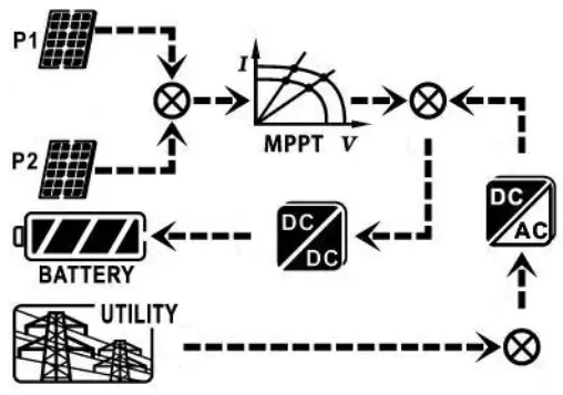
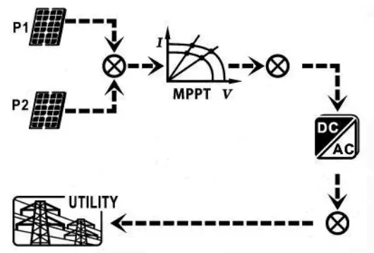
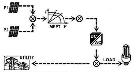
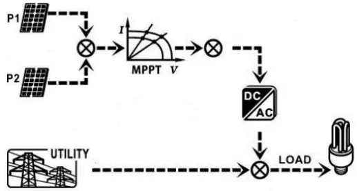
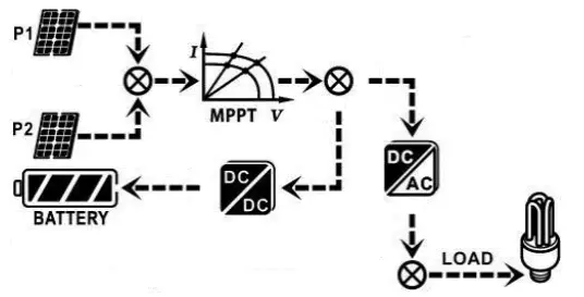
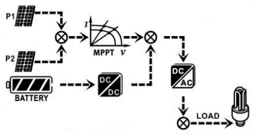
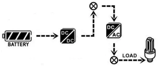
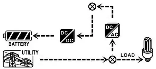
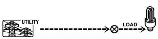
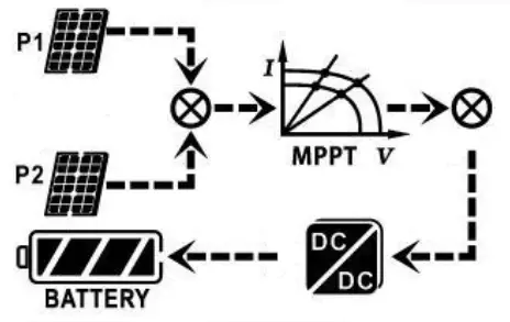
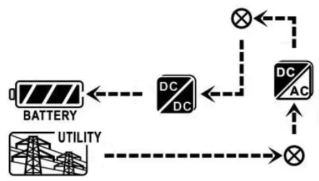
This hybrid PV inverter can provide power to connected loads by utilizing PV power, utility power and battery power.
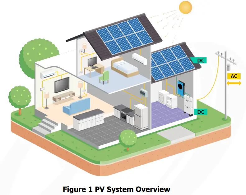
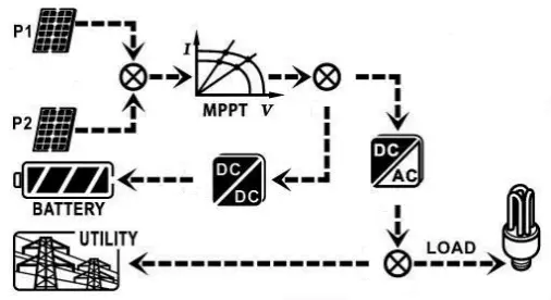
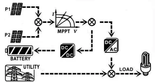
Depending on different power situations, this hybrid inverter is designed to generate continuous power from PV solar modules (solar panels), battery, and the utility. When MPP input voltage of PV modules is within acceptable range (see specification for the details), this inverter is able to generate power to feed the grid (utility) and charge battery. This inverter is only compatible with PV module types of single crystalline and poly crystalline.
Do not connect any PV array types other than these two types of PV modules to the inverter. Do not connect the positive or negative terminal of the solar panel to the ground. See Figure 1 for a simple diagram of a typical solar system with this hybrid inverter.
Note: By following the EEG standard, every inverter sold to German area is not allowed to charge battery from Utility. The relevant function is automatically disabled by the software.
Important Safety Warning
Before using the inverter, please read all instructions and cautionary markings on the unit and this manual. Store the manual where it can be accessed easily.
This manual is for qualified personnel. The tasks described in this manual may be performed by qualified personnel only.
General Precaution-
Conventions used:
WARNING! Warnings identify conditions or practices that could result in personal injury;
CAUTION! Caution identify conditions or practices that could result in damaged to the unit or other equipment connected. WARNING! Before installing and using this inverter, read all instructions and cautionary
markings on the inverter and all appropriate sections of this guide. WARNING! Normally grounded conductors may be ungrounded and energized when a ground fault is indicated. WARNING! This inverter is heavy. It should be lifted by at least two persons.![]()
![]() CAUTION! Authorized service personnel should reduce the risk of electrical shock by disconnecting AC, DC and battery power from the inverter before attempting any maintenance or cleaning or working on any circuits connected to the inverter. Turning off controls will not reduce this risk. Internal capacitors can remain charged for 5 minutes after disconnecting all sources of power.
CAUTION! Authorized service personnel should reduce the risk of electrical shock by disconnecting AC, DC and battery power from the inverter before attempting any maintenance or cleaning or working on any circuits connected to the inverter. Turning off controls will not reduce this risk. Internal capacitors can remain charged for 5 minutes after disconnecting all sources of power.![]() CAUTION! Do not disassemble this inverter yourself. It contains no user-serviceable parts. Attempt to service this inverter yourself may cause a risk of electrical shock or fire and will void the warranty from the manufacturer.
CAUTION! Do not disassemble this inverter yourself. It contains no user-serviceable parts. Attempt to service this inverter yourself may cause a risk of electrical shock or fire and will void the warranty from the manufacturer.![]() CAUTION! To avoid a risk of fire and electric shock, make sure that existing wiring is in good condition and that the wire is not undersized. Do not operate the Inverter with damaged or substandard wiring.
CAUTION! To avoid a risk of fire and electric shock, make sure that existing wiring is in good condition and that the wire is not undersized. Do not operate the Inverter with damaged or substandard wiring.![]() CAUTION! Under high temperature environment, the cover of this inverter could be hot enough to cause skin burns if accidentally touched. Ensure that this inverter is away from normal traffic areas.
CAUTION! Under high temperature environment, the cover of this inverter could be hot enough to cause skin burns if accidentally touched. Ensure that this inverter is away from normal traffic areas.![]() CAUTION! Use only recommended accessories from installer. Otherwise, not-qualified tools may cause a risk of fire, electric shock, or injury to persons. CAUTION! To reduce risk of fire hazard, do not cover or obstruct the cooling fan. CAUTION! Do not operate the inverter if it has received a sharp blow, been dropped, or otherwise damaged in any way. If the inverter is damaged, please call for an RMA (Return Material Authorization). CAUTION! AC breaker, DC switch and Battery circuit breaker are used as disconnect devices and these disconnect devices shall be easily accessible.
CAUTION! Use only recommended accessories from installer. Otherwise, not-qualified tools may cause a risk of fire, electric shock, or injury to persons. CAUTION! To reduce risk of fire hazard, do not cover or obstruct the cooling fan. CAUTION! Do not operate the inverter if it has received a sharp blow, been dropped, or otherwise damaged in any way. If the inverter is damaged, please call for an RMA (Return Material Authorization). CAUTION! AC breaker, DC switch and Battery circuit breaker are used as disconnect devices and these disconnect devices shall be easily accessible.
Before working on this circuit
Isolate inverter/Uninterruptible Power System (UPS)
– Then check for Hazardous Voltage between allterminals including the protective earth.![]() Risk of Voltage Backfeed
Risk of Voltage Backfeed
Symbols used in Equipment Markings
| Refer to the operating instructions | |
| Caution! Risk of danger |
| Caution! Risk of electric shock | |
| Caution! Risk of electric shock. Energy storage timed discharge for 5 minutes. | |
| Caution! Hot surface |
Unpacking & Overview
3-1. Packing List
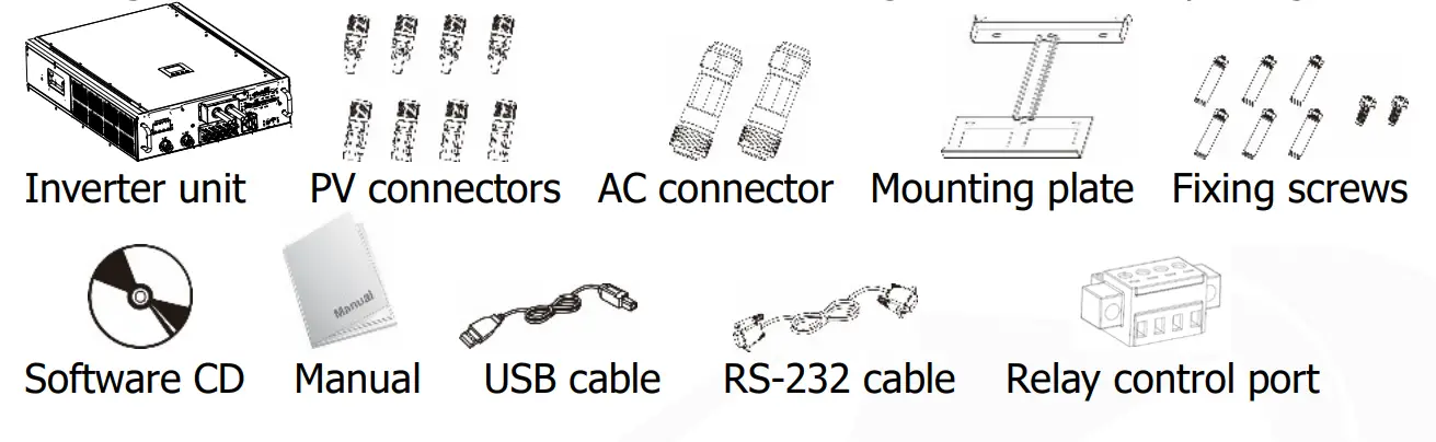
Before installation, please inspect the unit. Be sure that nothing inside the package is damaged. You should have received the following items inside of package:
3-2. Product Overview
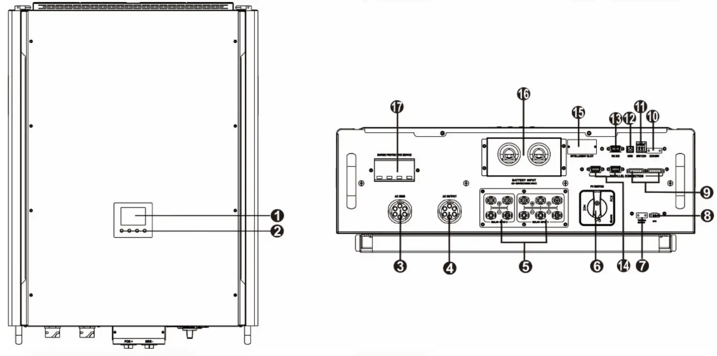
| 1) LCD display panel 2) Operation buttons 3) AC Grid connectors 4) AC output connectors (Load connection) 5) PV connectors 6) DC Switch 7) Battery thermal sensor 8) EPO 9) Current sharing port | 10) Relay control port 11) Dry contact 12) USB communication port 13) RS-232 communication port 14) Parallel communication port 15) Intelligent slot 16) Battery connectors 17) Connector for surge protective device (Reserve) |
Installation
4-1. Selecting Mounting Location
Consider the following points before selecting where to install:
- Do not mount the inverter on flammable construction materials.
- Mount on a solid surface
- This inverter can make noises during operation which may be perceived as a nuisance in a living area.
- Install this inverter at eye level in order to allow the LCD display to be read at all times.
- For proper air circulation to dissipate heat, allow a clearance of approx. 20 cm to the side and approx. 50 cm above and below the unit.
- Dusty conditions on the unit may impair the performance of this inverter.
- The ambient temperature should be between 0°C and 40°C and relative humidity should be between 5% and 85% to ensure optimal operation.
- The recommended installation position is to be adhered to vertical.
- For proper operation of this inverter, please use appropriate cables for grid connection.
- The pollution degree of the inverter is PD2. Select an appropriate mounting location. Install the solar inverter in a protected area that is dry, free of excessive dust and has adequate air flow. Do NOT operate it where the temperature and humidity is beyond the specific limits. (Please check the specs for the limitations.)
- Installation position shall not prevent access to the disconnection means.
- This inverter is designed with IP20 for indoor applications only.
- Regularly clean the fan filter.
4-2. Mounting Unit
WARNING!! Remember that this inverter is heavy! Please be carefully when lifting out from the package.
Installation to the wall should be implemented with the proper screws. After that, the device should be bolted on securely.
The inverter only can be used in a CLOSED ELECTRICAL OPERATING AREA. Only service person can enter into this area.
WARNING!! FIRE HAZARD.
SUITABLE FOR MOUNTING ON CONCRETE OR OTHER NON-COMBUSTIBLE SURFACE ONLY.
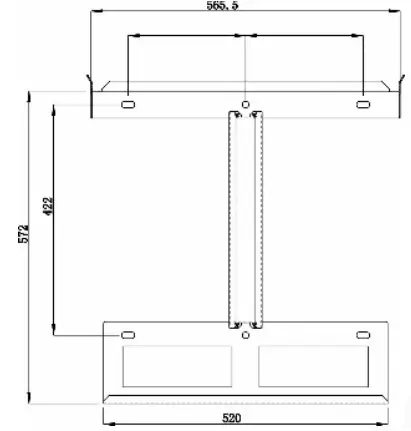
| 1. Drill six holes in the marked locations with supplied six screws.The reference tightening torque is 35 N.m. | 2. Raise the inverter and place it over the mounting plate. |
 | 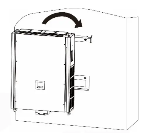 |
| 3. Fix the inverter in position by screwing the supplied two screws (M4*12) located on the top two sides of the inverter. | 4. Check if the inverter is firmly secured. |
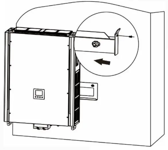 | 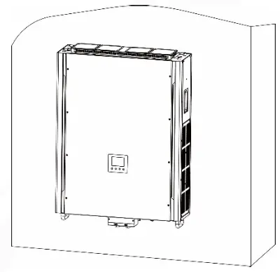 |
Grid (Utility) Connection
5-1. Preparation
NOTE: The overvoltage category of the AC input is III. It should be connected to the power distribution.
NOTE2: It’s strongly recommended to install the external surge protection device at the grid input. The recommended parameters of the SPD is below:
| Maximum Continuous Operating Voltage Uc (VAC) | 275V~400V |
| Voltage protection Level Up (VAC) kV | ≤1.0 |
| Nominal Discharge Current In (8/20s) kA | 20 |
| Maximum Discharge Current Imax (8/20s) kA | 40 |
| Response Time (ns) | <25 |
WARNING! It’s very important for system safety and efficient operation to use appropriate cable for grid (utility) connection. To reduce risk of injury, please use the proper recommended cable size as below.
Suggested cable requirement for AC wire
| Nominal Grid Voltage | 230VAC per phase |
| Conductor cross-section (mm2) | 10-16 |
| AWG no. | 8-6 |
5-2. Connecting to the AC Utility
Overview of AC Connection Socket
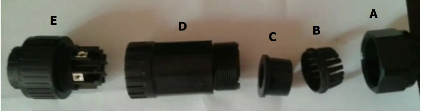
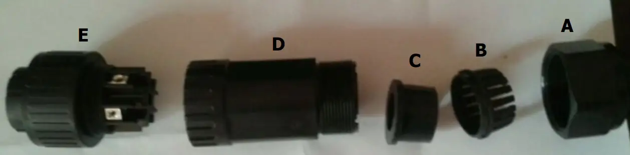
| Component | Description |
| A | Pressure dome |
| B | Clip |
| C | Sealing nut |
| D | Protective element |
| E | Socket element |
Step 1: Check the grid voltage and frequency with an AC voltmeter. It should be the same to “VAC” value on the product label.
Step 2: Turn off the circuit breaker.
Step 3: Remove insulation sleeve 13 mm for five conductors.
Step 4: Thread the five cables through pressure dome (A), clip (B), sealing nut (C) and protective element (D) in sequence.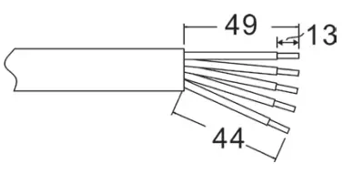
Step 5: Thread five cables through socket element (E) according to polarities indicated on it and tighten the screws to fix wires after connection.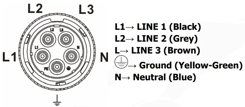
The reference tightening torque is 1.5-2.5 N.m.
Step 6: Push protective dome (D) on to socket element (E) until both are locked tightly.
Then, twist protective element (D) and pressure dome (A) so that all cables are firmly connected.

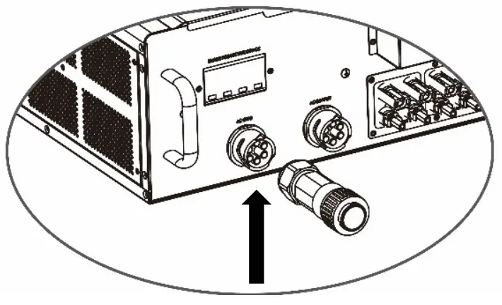
Step 7: Plug the AC connection socket into AC grid terminal of the inverter.
CAUTION: To prevent risk of electric shock, ensure the ground wire is properly earthed before operating this hybrid inverter no matter the grid is connected or not.
PV Module (DC) Connection
NOTE1: It’s strongly recommended to install the external surge protection device (SPD) at the solar input. The recommended parameters of the SPD is below:
| Maximum Continuous Operating Voltage Uc (VDC) | 600V~1000V |
| Voltage protection Level Up (VDC) kV | ≤2.0 |
| Nominal Discharge Current In (8/20s) kA | 20 |
| Maximum Discharge Current Imax (8/20s) kA | 40 |
| Response Time (ns) | <25 |
NOTE2: The overvoltage category of the PV input is II.
Please follow below steps to implement PV module connection:
WARNING: Because this inverter is non-isolated, only three types of PV modules are acceptable: single crystalline and poly crystalline with class A-rated and CIGS modules.
To avoid any malfunction, do not connect any PV modules with possibility of leakage current to the inverter. For example, grounded PV modules will cause leakage current to the inverter. When using CIGS modules, please be sure NOT grounding.
CAUTION: It’s requested to have PV junction box with surge protection. Otherwise, it will cause inverter damage when lightning occurs on PV modules.
Step 1: Check the input voltage of PV array modules. The acceptable input voltage of the inverter is 350VDC – 900VDC. Please make sure that the maximum current load of
MPPT1 input connector is less than 37.2A; MPPT 2 input connector is 18.6A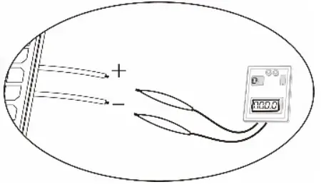
CAUTION: Exceeding the maximum input voltage can destroy the unit!! Check the system before wire connection.
Step 2: Disconnect the circuit breaker and switch off the DC switch.
Step 3: Assemble provided PV connectors with PV modules by the following below steps.
Components for PV connectors and Tools:
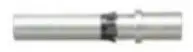
| Female connector housing |  |
| Female terminal |
|
| Male connector housing |  |
| Male terminal | |
| Crimping tool and spanner |  |
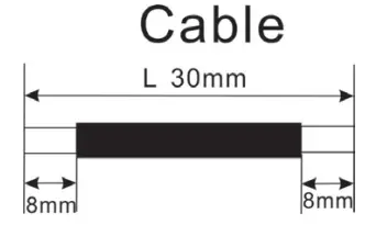
Cable preparation and connector assembly process:
Strip one cable 8 mm on both end sides and be careful NOT to nick conductors.
Insert striped cable into female terminal and crimp female terminal as shown below charts.

Insert assembled cable into female connector housing as shown below charts.

Insert striped cable into male terminal and crimp male terminal as shown below charts.

Insert assembled cable into male connector housing as shown below charts.

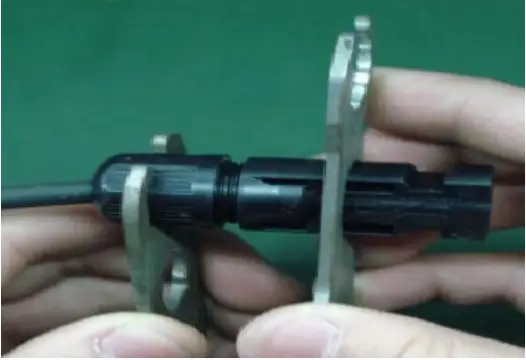
Then, use spanner to screw pressure dome tightly to female connector and male connector as shown below.
Step 4: Check correct polarity of connection cable from PV modules and PV input connectors. Then, connect positive pole (+) of connection cable to positive pole (+) of PV input connector. Connect negative pole (-) of connection cable to negative pole (-) of PV input connector.
WARNING! It’s very important for system safety and efficient operation to use appropriate cable for PV module connection. To reduce risk of injury, please use the proper recommended cable size as below.
| Conductor cross-section (mm2) | AWG no. |
| 6 | 10 |
CAUTION: Never directly touch terminals of the inverter. It will cause lethal electric exposed to sunlight, it may generate DC voltage to the inverter.
Recommended Panel Configuration
| Solar Panel Spec. (reference) – 250Wp – Vmp: 36.7Vdc – Imp: 6.818A – Voc: 44Vdc – Isc: 7.636A – Cells: 72 | SOLAR INPUT 1 | SOLAR INPUT 2 | Q’ty of panels | Total Input Power |
| (Min in series: 11pcs; Max. in series: 18pcs) | ||||
| 11pcs in series | x | 11pcs | 2750W | |
| x | 11pcs in series | 11pcs | 2750W | |
| 11pcs in series | 11pcs in series | 22pcs | 5500W | |
| 11pcs in series, 2 parallel | x | 22pcs | 5500W | |
| x | 11pcs in series, 2 parallel | 22pcs | 5500W | |
| 18pcs in series | 18pcs in series | 36pcs | 9000W | |
| 14pcs in series, 2 parallel | 14pcs in series | 42pcs | 10500W | |
| 18pcs in series, 2 parallel | 18pcs in series | 54pcs | 13500W | |
| 15pcs in series, 2 parallel | 15pcs in series, 2 parallel | 60pcs | 15000W | |
| 15pcs in series,4 parallel | 15pcs in series, 2 parallel | 90pcs | .22500W | |
Battery Connection
CAUTION: Before connecting to batteries, please install separately a DC circuit breaker between inverter and batteries.
NOTE1: Please only use sealed lead acid battery, vented and Gel battery. Please check maximum charging voltage and current when first using this inverter. If using Lithium iron or Nicd battery, please consult with installer for the details.
NOTE2: Please use 60VDC/300A circuit breaker.
NOTE3: The overvoltage category of the battery input is II.
Please follow below steps to implement battery connection:
Step 1: Check the nominal voltage of batteries. The nominal input voltage for inverter is 48VDC.
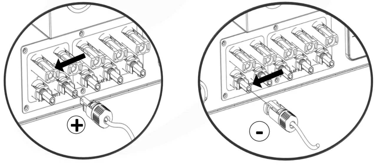
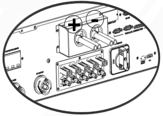
Step 2: Use two battery cables. Remove insulation sleeve 12 mm and insert conductor into cable ring terminal. Refer to right chart.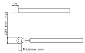 Step 3: Remove battery cover and follow battery polarity guide printed near the battery terminal! Place the external battery cable ring terminal over the battery terminal.
RED cable to the positive terminal (+);
BLACK cable to the negative terminal (-).
WARNING! Wrong connections will damage the unit permanently.
Step 4: Make sure the wires are securely connected. The reference tightening torque is 5.5~7.0 N.m.
WARNING! It’s very important for system safety and efficient operation to use appropriate cable for battery connection. To reduce risk of injury, please use the proper recommended cable size as below.
| Nominal Battery Voltage | 48V |
| Conductor cross-section (mm2 ) | 182 |
| AWG no. | 2*1/0 |
| Protective earthing (battery side) | 150mm2 (300kcmil) |
Load (AC Output) Connection
8-1. Preparation
CAUTION: To prevent further supply to the load via the inverter during any mode of operation, an additional disconnection device should be placed on in the building wiring installation.
WARNING! It’s very important for system safety and efficient operation to use appropriate cable for AC connection. To reduce risk of injury, please use the proper recommended cable size as below.
| Nominal Grid Voltage | 208/220/230/240 VAC per phase |
| Conductor cross-section (mm2) | 5.5-10 |
| AWG no. | 10-8 |
8-2. Connecting to the AC output
Overview of Load Connection Socket
| Component | Description |
| A | Pressure dome |
| B | Clip |
| C | Sealing nut |
| D | Protective element |
| E | Socket element |
Step 1: Remove insulation sleeve 8.5 mm for five conductors.
Step 2: Thread the five cables through pressure dome (A), clip (B), sealing nut (C) and protective element (D)
in sequence.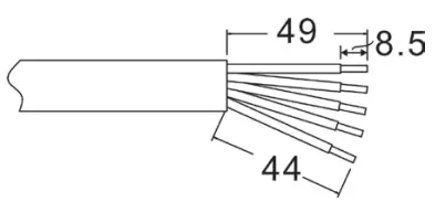 Step 3: Thread five cables through socket element (E) according to polarities indicated on it and tighten the screws to fix wires after connection.
 Step 4: Push protective dome (D) on to socket element (E) until both are locked tightly.
Then, twist protective element (D) and pressure dome (A) so that all cables are firmly connected.

Step 5: Plug the socket into the terminal.
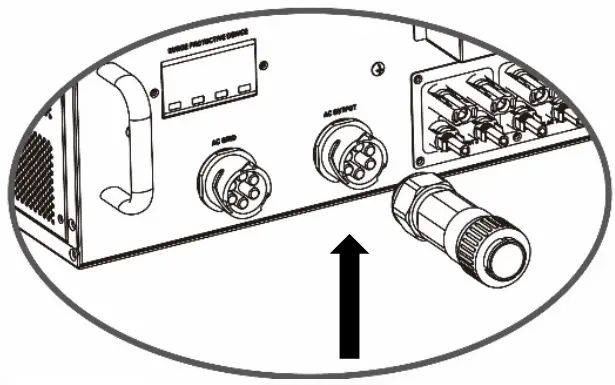
CAUTION: It’s only allowed to connect load to “AC Output Connector”. Do NOT connect the utility to “AC Output Connector”.
CAUTION: Be sure to connect L terminal of load to L terminal of “AC Output Connector” and N terminal of load to N terminal of “AC Output Connector”. The G terminal of “AC Output Connector” is connected to grounding of the load. Do NOT mis-connect.
Communication
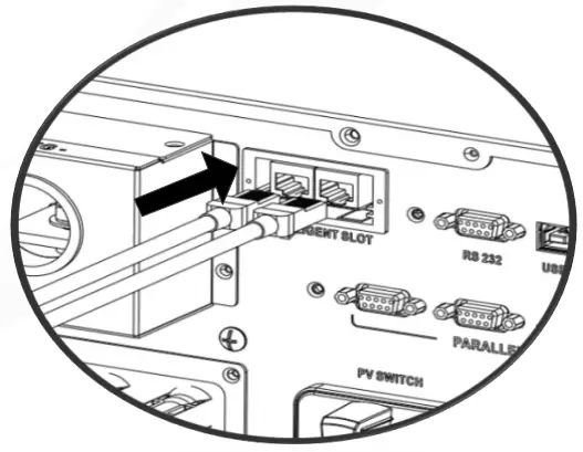
The inverter is equipped with several communication ports and it is also equipped with a slot for alternative communication interfaces in order to communicate with a PC with corresponding software. This intelligent slot is suitable to install with SNMP card and Modbus card. Follow below procedure to connect communication wiring and install the software.
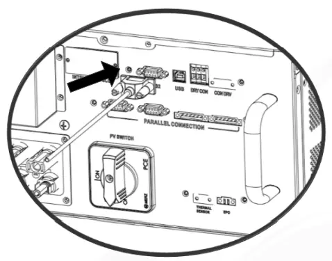
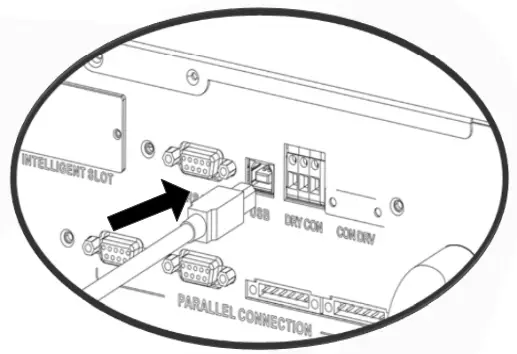
| For RS232 port, you should use a DB9 cable as follows: | For USB port, you should use a USB cable as follows: |
 |  |
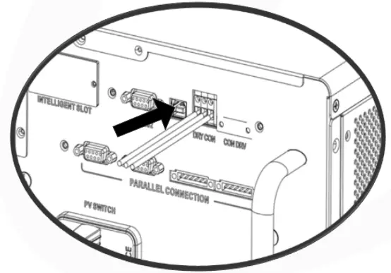
| For Dry contact port, please remove insulation sleeve 8 mm for three conductors and insert three cables into ports | For SNMP or MODBUS card, you should use RJ45 cables as follows: |
 |  |
Please install monitoring software in your computer. Detailed information is listed in the next chapter. After software is installed, you may initial the monitoring software and extract data through communication port.
Dry Contact Signal
There is one dry contact available on the bottom panel. It could be used to remote control for external generator.
10-1. Electric Parameter
| Parameter | Symbol | Max. | Unit |
| Relay DC voltage | Vdc | 30 | V |
| Relay DC current | Idc | 1 | A |
Note: The application of the dry contact should not exceed the electric parameter shown as above. Otherwise, the internal relay will be damaged.
10-2. Function Description
| Unit Status | Condition | Dry contact port: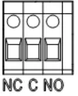 | |
| NO&C | NC&C | ||
| Power Off | Unit is off and no output is powered. | Open | Close |
| Power On | Battery voltage is lower than setting battery cut-off discharging voltage when grid is available. | Close | Open |
| Battery voltage is lower than setting battery cut-off discharging voltage when grid is unavailable. | Close | Open | |
| Battery voltage is higher than below 2 setting values: 1. Battery re-discharging voltage when grid is available. 2. Battery re-discharging voltage when grid unavailable. | Open | Close | |
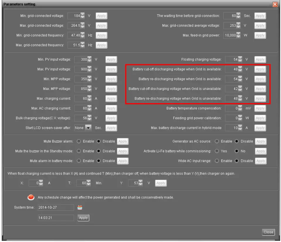
You can set the related parameters in software. Refer to below chart:
Relay Control Port
This port is available to provide a power source (230V/8A) to trigger external relay. This function is only valid for Grid-tie with backup II mode.
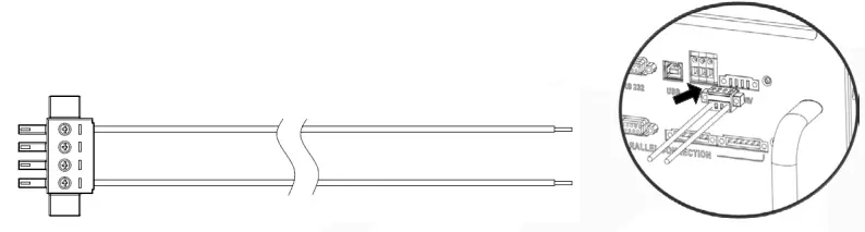
11-1. Interface Configuration
There are four pins on this port. However, only Pin 1 and Pin 4 are worktable.
Please use supplied cables to connect Pin 1 and Pin 4 shown as below charts.
11-2. Function Description
| 12- Unit status | Condition | Output voltage from relay control port |
| Power Off | Unit is off and no output is powered. | 0V |
| Power On | When the unit is working at inverter mode and grid is not available Condition 1: 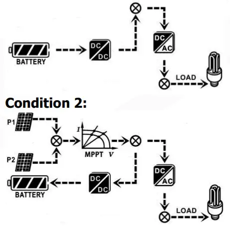 | 230V |
| Power on | Condition 3: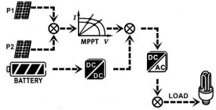 | 230V |
| When the unit is not working at inverter mode or grid is available. | 0V |
12-2. Application
Below chart is recommended circuit wiring.
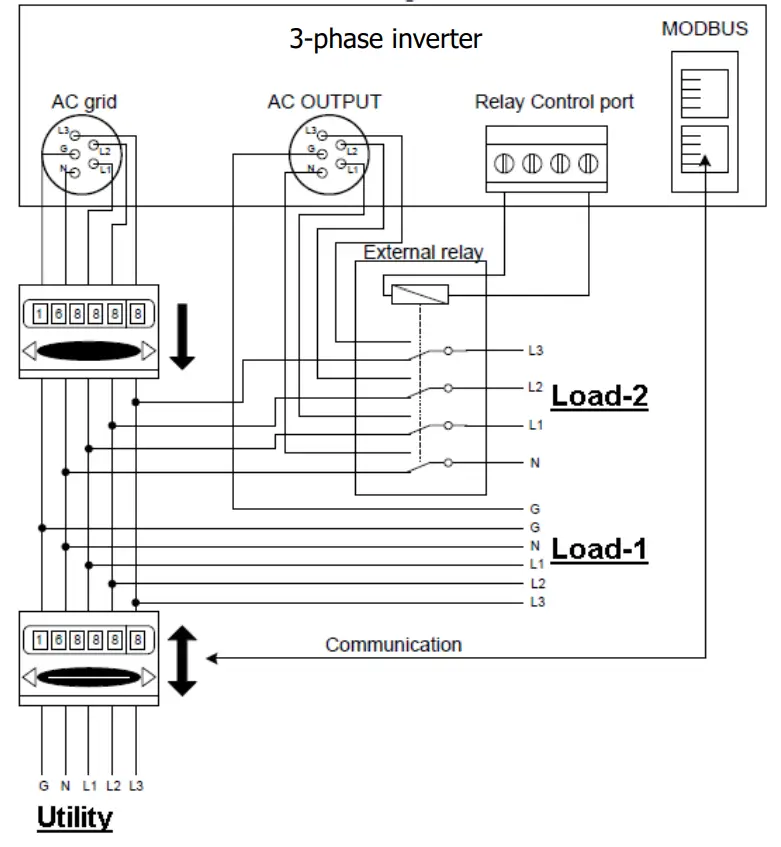
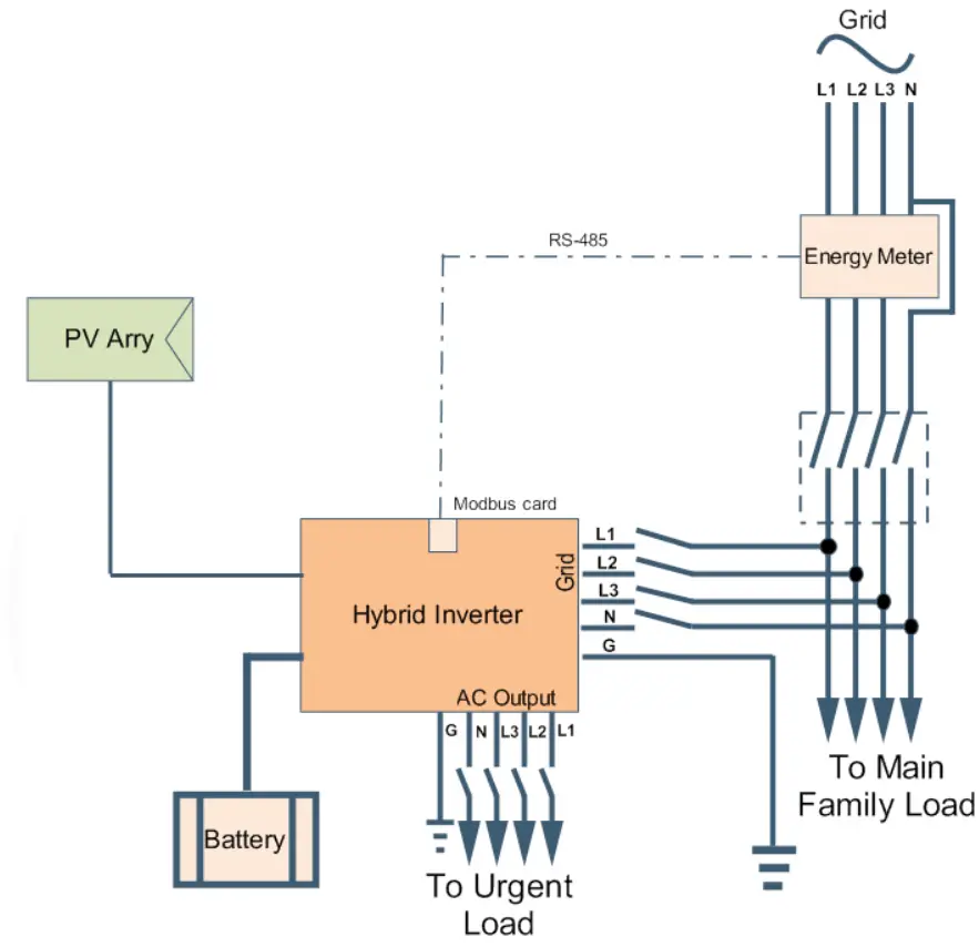
12. Application with Energy Meter
With Modbus card II and energy meter, hybrid inverter can be easily integrated into the existing household system. For details please refer to Modbus card II manual.
Note: this application is only valid for Grid-Tie with Backup II mode.
Equipped with Modbus card II, hybrid inverter is connected to energy meter with RS485 communication port. It’s to arrange self-consumption via Modbus card to control power generation and battery charging of the inverter.
Commissioning
Step 1: Check the following requirements before commissioning:
- Ensure the inverter is firmly secured
- Check if the open circuit DC voltage of PV module meets requirement (Refer to Section 6)
- Check if the open circuit utility voltage of the utility is at approximately same to the nominal expected value from local utility company.
- Check if connection of AC cable to grid (utility) is correct if the utility is required.
- Full connection to PV modules.
- AC circuit breaker (only applied when the utility is required), batter circuit breaker, and DC circuit breaker are installed correctly.
Step 2: Switch on the battery circuit breaker and then switch on PV DC breaker. After that, if there is utility connection, please switch on the AC circuit breaker. At this moment, the inverter is turned on already. However, there is no output generation for loads. Then:
- If LCD lights up to display the current inverter status, commissioning has been successfully. After pressing “ON” button for 1 second when the utility is detected, this inverter will start to supply power to the loads. If no utility exists, simply press “ON” button for 3 seconds. Then, this inverter will start to supply power to the loads.
- If a warning/fault indicator appears in LCD, an error has occurred to this inverter.
Please inform your installer.
Step 3: Please insert CD into your computer and install monitoring software in your PC.
Follow below steps to install software.
- Follow the on-screen instructions to install the software.
- When your computer restarts, the monitoring software will appear as shortcut icon located in the system tray, near the clock.
NOTE: If using 22odbus card as communication interface, please install bundled software. Check local dealer for the details.
Initial Setup
Before inverter operation, it’s required to set up “Operation Mode” via software. Please strictly follow below steps to set up. For more details, please check software manual.
Step 1: After turning on the inverter and installing the software, please click “Open Monitor” to enter main screen of this software.
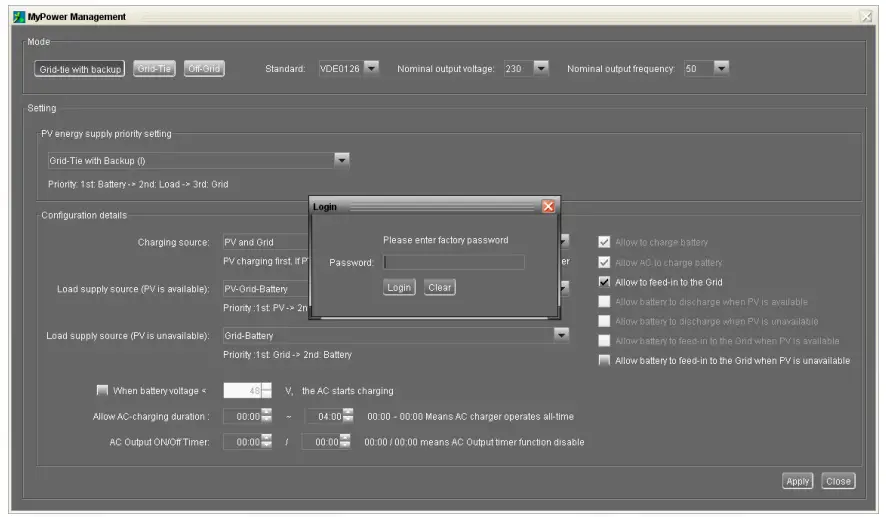
Step 2: Log in into software first by entering default password “administrator”.
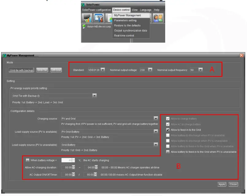
Step 3: Select Device Control>>MyPower Management. It is to set up inverter operation mode and personalized interface. Refer to diagram below.
Mode
There are three operation modes: Grid-tie with backup, Grid-Tie and Off-Grid.
- Grid-tie with backup: PV power can feed-in back to grid, provide power to the load and charge battery. There are four options available in this mode: Gridtie with backup I, II, III and IV.
In this mode, users can configure PV power supply priority, charging source priority and load supply source priority.
However, when Grid-tie with backup IV option is selected in PV energy supply priority, the inverter is only operated between two working logics based on defined peak time and off-peak time of electricity. Only peak time and off-peak time of electricity are able to set up for optimized electricity usage. - Grid-Tie: PV power only can feed-in back to grid.
- Off-Grid: PV power only provides power to the load and charge battery. No feed-in back to grid is allowed.
SECTION A:
Standard: It will list local grid standard. It’s requested to have factory password to make any modifications. Please check local dealer only when this standard change is requested.
CAUTION: Wrong setting could cause the unit damage or not working.
Nominal Output Voltage: 230V.
Nominal Output Frequency: 50HZ.
SECTION B:
This section contents may be different based on different selected types of operations.
Allow AC charging duration: It’s a period time to allow AC (grid) to charge battery.
When the duration is set up as 0:00-00:00, it means no time limitation for AC to charge battery.
AC output ON/Off Timer: Set up on/off time for AC output of inverter. If setting it as 00:00/00:00, this function is disabled.
Allow to charge battery: This option is automatically determined by setting in “Charging source”. It’s not allowed to modify here. When “NONE” is selected in charging source section, this option becomes unchecked as grey text.
Allow AC to charge battery: This option is automatically determined by setting in ”Charging source”. It’s not allowed to modify here. When “Grid and PV” or “Grid or PV” is selected in charging source section, this option is default selected. Under
Grid-tie mode, this option is invalid.
Allow to feed-in to the Grid: This option is only valid under Grid-tie and Grid-tie with backup modes. Users can decide if this inverter can feed-in to the grid.
Allow battery to discharge when PV is available: This option is automatically determined by setting in “Load supply source (PV is available)”. When “Battery” is higher priority than “Grid” in Load supply source (PV is available), this option is default selected. Under Grid-tie, this option is invalid.
Allow battery to discharge when PV is unavailable: This option is automatically determined by setting in “Load supply source (PV is unavailable)”. When “Battery” is higher priority than “Grid” in Load supply source (PV is unavailable), this option is default selected. Under Grid-tie mode, this option is invalid.
Allow battery to feed-in to the Grid when PV is available: This option is only valid in Grid-tie with backup II or Grid-tie with backup III modes.
Allow battery to feed-in to the Grid when PV is unavailable: This option is only valid in all options of Grid-tie with backup mode.
Grid-tie with backup
- Grid-tie with backup (I) :
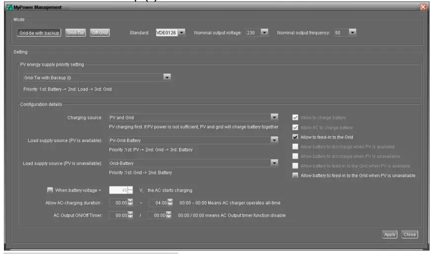
PV energy supply priority setting: 1st Battery, 2nd Load and 3rd Grid.
PV power will charge battery first, then provide power to the load. If there is any remaining power left, it will feed-in to the grid.
Battery charging source:
- PV and Grid (Default) It’s allowed to charge battery from PV power first. If it’s not sufficient, grid will charge battery.
- PV only It is only allow PV power to charge battery.
- None It is not allowed to charge battery no matter it’s from PV power or grid.
Load supply source:
When PV power is available: 1st PV, 2nd Grid, 3rd Battery
If battery is not fully charged, PV power will charge battery first. And remaining PV power will provide power to the load. If it’s not sufficient, grid will provide power to the load. If grid is not available at the same time, battery power will back up.
When PV power is not available:
- 1st Grid, 2nd Battery (Default) Grid will provide power to the load at first. If grid is not available, battery power will provide power backup.
- 1st Battery, 2nd Grid Battery power will provide power to the load at first. If battery power is running out, grid will back up the load.
NOTE: This option will become ineffective during AC charging time and the priority will automatically become 1st Grid and 2n° Battery order. Otherwise, it will cause battery damage.
- Grid-tie with backup (II) :
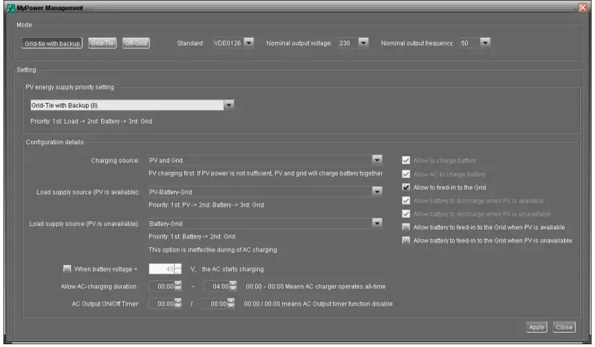
PV energy supply priority setting:
1st Load, 2nd Battery and 3rd Grid. PV power will provide power to the load first. Then, it will charge battery. If there is any remaining power left, it will feed-in to the grid.
Battery charging source:
- PV and Grid It’s allowed to charge battery from PV power first. If it’s not sufficient, grid will charge battery.
- PV only It is only allow PV power to charge battery.
- None It is not allowed to charge battery no matter it’s PV power or grid.
Load supply source:
When PV power is available:
- 1st PV, 2nd Battery, 3rd Grid PV power will provide power to the load first. If it’s not sufficient, battery power will provide power to the load. When battery power is running out or not available, grid will back up the load.
- 1st pv, 2nd Grid, 3rd Battery PV power will provide power to the load first. If it’s not sufficient, grid will provide power to the load. If grid is not available at the same time, battery power will back up.
When PV power is not available:
- 1st Grid, 2nd Battery: Grid will provide power to the load at first. If grid is not available, battery power will provide power backup.
- 1st Battery, 2″1 Grid: Battery power will provide power to the load at first. If battery power is running out, grid will back up the load
NOTE: This option will become ineffective during AC charging time and the priority will automatically become 1st Grid and 2nd Battery order. Otherwise, it will cause battery damage.
- Grid-tie with backup (III):
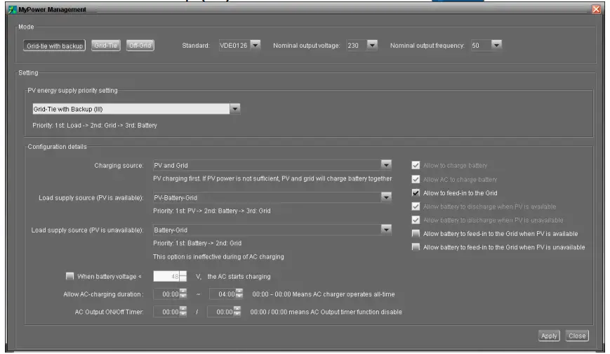
PV energy supply priority setting:
1st Load, 2nd Grid and 3rd Battery PV power will provide power to the load first. If there is more PV power available, it will feed-in to the grid. If feed-in power reaches max. feed-in power setting, the remaining power will charge battery.
NOTE: The max. feed-in grid power setting is available in parameter setting. Please refer to software manual.
Battery charging source:
- PV and Grid: It’s allowed to charge battery from PV power first. If it’s not sufficient, grid will charge battery.
- PV only: It is only allow PV power to charge battery.
- None: It is not allowed to charge battery no matter it’s PV power or grid.
Load supply source:
When PV power is available:
- pt PV, 2nd Battery, 3rd Grid PV power will provide power to the load first. If it’s not sufficient, battery power will provide power to the load. When battery power is running out or not available, grid will back up the load.
- 1st pv, 2nd Grid, 3rd Battery PV power will provide power to the load first. If it’s not sufficient, grid will provide power to the load. If grid is not available at the same time, battery power will back up.
When PV power is not available:
- 1st Grid, 2nd Battery: Grid will provide power to the load at first. If grid is not available, battery power will provide power backup.
Grid: Battery power will provide power to the load at first. If battery power is running out, grid will back up the load.
NOTE: This option will become ineffective during AC charging time and the priority will automatically become 1st Grid and 2nd - 1st Batter y, 2nd Battery order. Otherwise, it will cause battery damage.
Grid-tie with backup (IV): Users are only allowed to set up peak time and offpeak electricity demand.
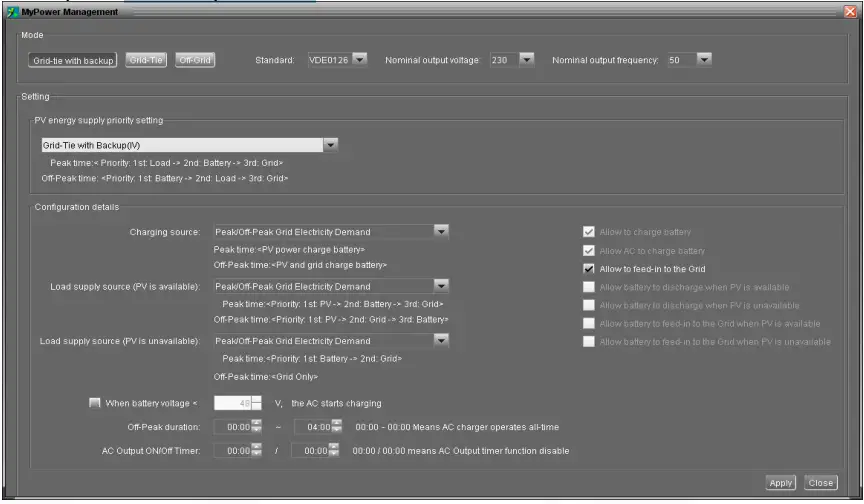
Working logic under peak time:
PV energy supply priority: 1st Load, 2nd Battery and 3rd Grid
PV power will provide power to the load first. If PV power is sufficient, it will charge battery next. If there is remaining PV power left, it will feed-in to the grid. Feed-in to the grid is default disabled.
Battery charging source: PV only
Only after PV power fully supports the load, the remaining PV power is allowed to charge battery during peak time.
Load supply source: 1st P V, 2nd Battery, 3rd Grid
PV power will provide power to the load first. If PV power is not sufficient, battery power will back up the load. If battery power is not available, grid will provide the load. When PV power is not available, battery power will supply the load first. If battery power is running out, grid will back up the load.
Working logic under off-peak time:
PV energy supply priority: 1st Battery, 2nd Load and 3rd Grid
PV power will charge battery first. If PV power is sufficient, it will provide power to the loads. The remaining PV power will feed to the grid.
NOTE: The max. feed-in grid power setting is available in parameter setting.
Please refer to software manual.
Battery charging source: PV and grid charge battery
PV power will charge battery first during off-peak time. If it’s not sufficient, grid will charge batter y.
Load supply source: 1st P V, 2nd Grid, 3rd
Battery
When battery is fully charged, remaining PV power will provide power to the load first. If PV power is not sufficient, grid will back up the load. If grid power is not available, battery power will provide power to the load.
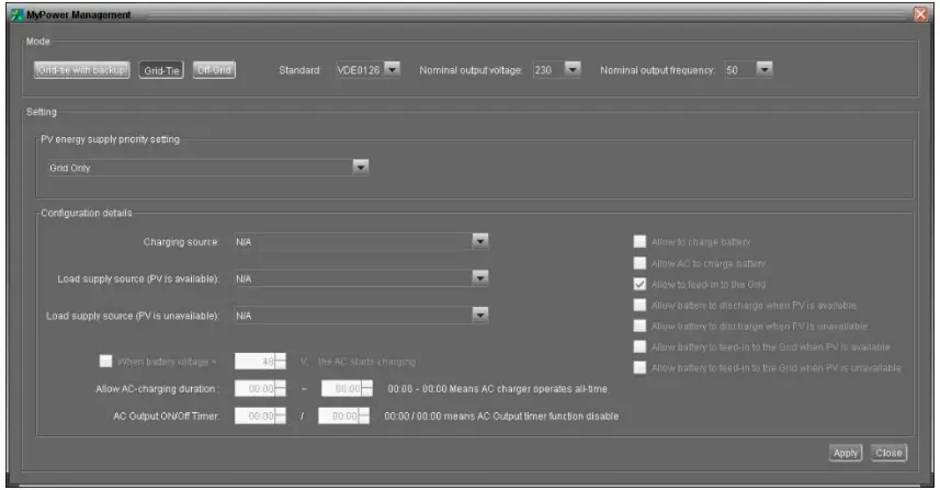
Grid-Tie
Under this operation mode, PV power only feeds-in to the grid. No priority setting is available.
Off-Grid
- Off-Grid (I): Default setting for off-grid mode.
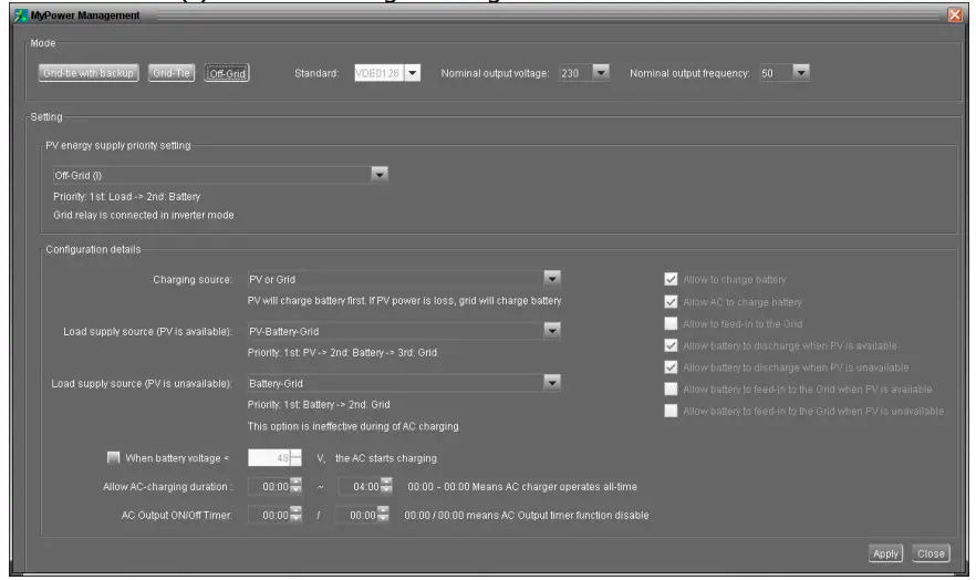
PV energy supply priority setting: 1st Load, 2nd Battery
PV power will provide power to the load first and then charge battery. Feed-in to the grid is not allowed under this mode. At the same time, the grid relay is connected in Inverter mode. Besides, it will avoid overload fault because grid can supply load when connected load is over 15KW.
Battery charging source:
- PV or Grid: If there is remaining PV power after supporting the loads, it will charge battery first. Only until PV power is not available, grid will charge battery. (Default)
- PV only: It is only allow PV power to charge battery.
- None: It is not allowed to charge battery no matter it’s PV power or grid.
Load supply source:
When PV power is available:
- 1st P V, 2nd Battery, 3rd Grid (Default)
PV power will provide power to the load first. If it’s not sufficient, battery power will provide power to the load. When battery power is running out or not available, grid
will back up the load. - 1st P V, 2nd Grid, 3rd Battery
PV power will provide power to the load first. If it’s not sufficient, grid will provide power to the load. If grid is not available at the same time, battery power will back up.
When PV power is not available:
- 1st Grid, 2nd Battery
Grid will provide power to the load at first. If grid is not available, battery power will provide power backup. - 1st Battery, 2nd Grid (Default)
Battery power will provide power to the load at first. If battery power is running out, grid will back up the load.
NOTE: This option will become ineffective during AC charging time and the priority will automatically become 1st Grid and 2nd Battery order. Otherwise, it will cause battery damage.
- Off-Grid (II)
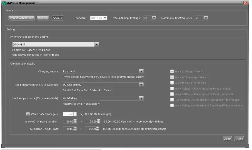
PV energy supply priority setting: 1st Battery, 2nd Load
PV power will charge battery first. After battery is fully charged, if there is remaining PV power left, it will provide power to the load. Feed-in to the grid is not allowed under this mode. At the same time, the grid relay is connected in Inverter mode. Besides, it will avoid overload fault because grid can supply load when connected load is over 15KW.
Battery charging source:
- PV or Grid: If there is remaining PV power after supporting the loads, it will charge battery first. Only until PV power is not available, grid will charge battery.
- PV only: It is only allow PV power to charge battery.
- None: It is not allowed to charge battery no matter it’s PV power or grid.
NOTE: It’s allowed to set up AC charging duration.
Load supply source:
When PV power is available: 1st P V, 2nd Grid, 3rd Battery
PV power will provide power to the load first. If it’s not sufficient, grid will provide power to the load. If grid is not available at the same time, battery power will back up.
When PV power is not available:
- 1st Grid, 2nd
Battery: Grid will provide power to the load at first. If grid is not available, battery power will provide power backup. - 1st Batter y, 2nd Grid: Battery power will provide power to the load at first. If battery power is running out, grid will back up the load.
NOTE: This option will become ineffective during AC charging time and the priority will automatically become 1st Grid and 2nd Battery order. Otherwise, it will cause
battery damage.
- Off-Grid (III)
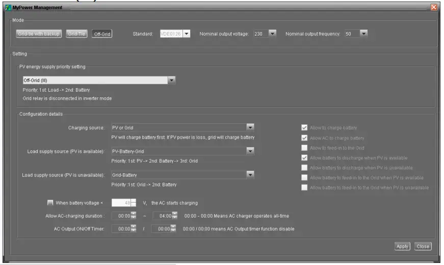
PV energy supply priority setting: 1st Load, 2nd Battery
PV power will provide power to load first and then charge battery. Feed-in to the grid is not allowed under this mode. The grid relay is NOT connected in Inverter mode. If connected load is over 15KW and grid is available, this inverter will allow grid to provide power to the loads and PV power to charge battery. Otherwise, this inverter will activate fault protection.
Battery charging source:
- PV or Grid: If there is remaining PV power after supporting the loads, it will charge battery first. Only until PV power is not available, grid will charge battery.
- PV only: It is only allow PV power to charge battery.
- None: It is not allowed to charge battery no matter it’s PV power or grid.
NOTE: It’s allowed to set up AC charging duration.
Load supply source:
When PV power is available: st P V, 2 nd Battery, 3rd Grid
PV power will provide power to the load first. If it’s not sufficient, battery power will back up the load. Only after battery power is running, Grid will back up the load.
When PV power is not available:
- 1st Grid, 2nd Battery: Grid will provide power to the load at first. If grid is not available, battery power will provide power backup.
- 1 st Batter y, 2 nd Grid: Battery power will provide power to the load at first. If battery power is running out, grid will back up the load.
NOTE: This option will become ineffective during AC charging time and the priority will automatically become 1st Grid and 2nd Battery order. Otherwise, it will cause battery damage.
Operation
15-1. Interface
This display is operated by four buttons.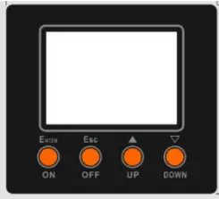
NOTICE: To accurately monitor and calculate the energy generation, please calibrate the timer of this unit via software every one month. For the detailed calibration, please
check the user manual of bundled software.
15-2. LCD Information Define
| Display | Function |
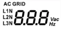 | Indicates AC input voltage or frequency. Vac: voltage, Hz: frequency, L1N/L2N/L3N: Line phase |
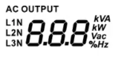
| Indicates AC output power, voltage, frequency, or load percentage. KVA: apparent power, KW: active power, Vac: Voltage, %: Load percentage, Hz: frequency, L1N/L2N/L3N: AC output phase |
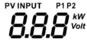 | Indicates PV input voltage or power. Volt: voltage, KW: power, P1: PV input 1, P2: PV input 2 |
 | Indicates battery voltage or percentage. Volt: voltage, %: percentage |
 | Indicates charging current to battery or discharging current from battery. |
| Indicates that the warning occurs. |
| Indicates that the fault occurs. | |
 | Indicates fault code or warning code. |
 | Indicates date and time, or the date and time users set for querying energy generation. |
 | Indicates solar panels. Icon flashing indicates PV input voltage or is out of range. |
 | Indicates utility.Icon flashing indicates utility voltage or frequency is out of range. |
 | Indicates battery condition. And the lattice of the icon indicates battery capacity. |
 | Icon |
 | Icon |
 | Indicates AC output for loads is enabled and inverter is providing power to the connected loads. |
 | Indicates AC output for loads is enabled but there is no power provided from inverter. At this time, no battery and the utility are available. Only PV power exists but is not able to provide power to the connected loads. |
| Indicates overload. | |
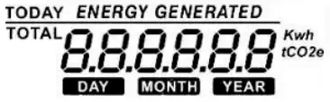 | Indicates PV energy generated. |
 | Indicates inverter is connecting with Energy meter. |
15-3. Button Definition
| Button | Operation | Function |
| ENTER/ON | Short press. | Enter query menu. |
| If it’s in query menu, press this button to confirm selection or entry. | ||
| Press and hold the button for approximately 1 second when the utility is detected or 3 seconds without the utility. | This inverter is able to provide power to connected loads via AC output connector. | |
| ESC/OFF | Short press. | Return to previous menu. |
| Press and hold the button until the buzzer continuously sounds. | Turn off power to the loads. | |
| Up | Short press. | Select last selection or increase value. |
| Down | Short press. | If it’s in query menu, press this button to jump to next selection or decrease value. |
| Mute alarm in standby mode or battery mode. |
NOTE: If backlight shuts off, you may activate it by pressing any button. When an error occurs, the buzzer will continuously sound. You may press any button to mute it.
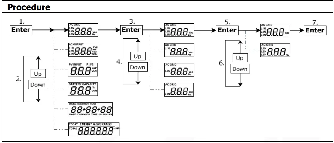
15-4. Query Menu Operation
The display shows current contents that have been set. The displayed contents can be changed in query menu via button operation. Press ‘Enter’ button to enter query menu.
There are seven query selections:
- Input voltage or frequency of AC input.
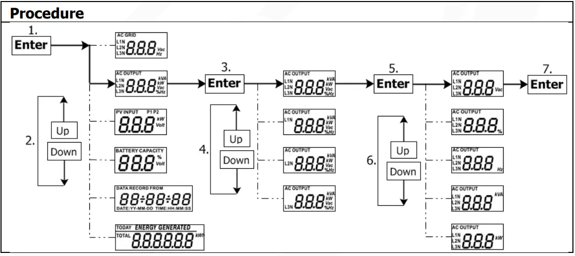
- Frequency, voltage, power or load percentage of AC output.
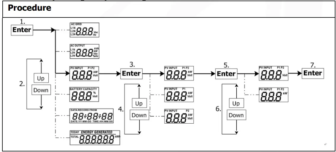
- Input voltage or power of PV input.
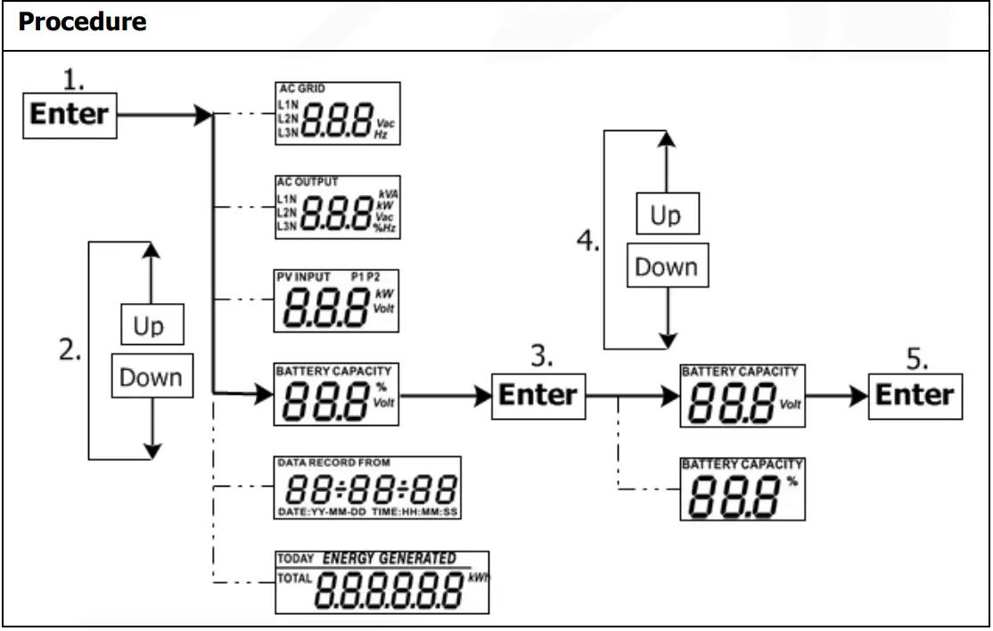
- Battery voltage or capability percentage.
- Date and time.
- Today or total energy generated.
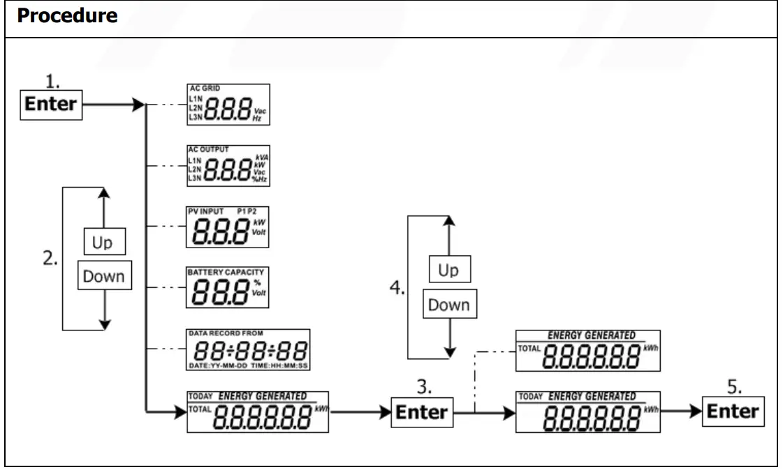
Setting Display Procedure
- Input voltage or frequency of AC input
- Frequency, voltage, power or percentage of AC output
- Input voltage or power of PV input.
- Battery voltage or percentage.
- Date and time.
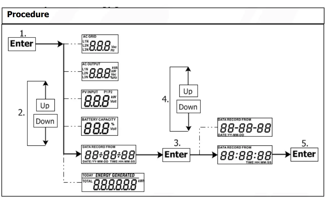
- Today or total energy generated.
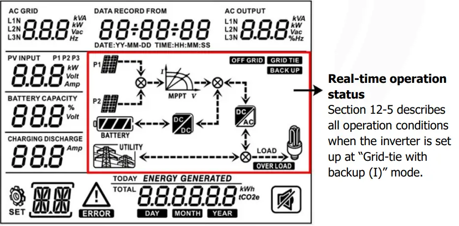
15-5. Operation Mode & Display
Below is only contained LCD display for grid-tie with backup mode (I). If you need to know other operation mode with LCD display, please check with installer.
Inverter mode with grid connected
This inverter is connected to grid and working with DC/INV operation.
| LCD Display | Description |
 | PV power is sufficient to charge battery, provide power to loads, and then feed in to the grid. |
 | PV power is sufficient to charge the battery first. However, remaining PV power is not sufficient to back up the load. Therefore, remaining PV power and the utility are supplying power to the connected load. |
 | PV power is generated, but not sufficient enough to charge battery by itself. PV power and the utility are charging battery at the same time. And the utility is also supplying power to the connected load. |
 | This inverter is disabled to generate power to the loads via AC output. PV power is sufficient to charge battery first. Remaining PV power will feed in back to grid. |
 | This inverter is disabled to generate power to the loads via AC output. PV power and utility are charging battery at the same time because of insufficient PV power. |
 | This inverter is disabled to generate power to the loads via AC output. PV power is feeding power back to the grid. |
 | PV power is sufficient to provide power to loads and feed power back to the grid. |
 | PV power and utility are providing power to the connected loads because of insufficient PV power. |
Inverter mode without grid connected
This inverter is working with DC/INV operation and not connecting to the grid.
| LCD Display | Description |
 | PV power is sufficient to charge battery and provide power to the connected loads. |
 | PV power is generated, but not sufficient to power loads by itself. PV power and battery are providing power to the connected loads at the same time. |
 | Only battery power is available to provide power to connected loads. |
Bypass mode
The inverter is working without DC/INV operation and connecting to the loads.
| LCD Display | Description |
 | Only utility is charging battery and providing power to connected loads. |
 | Only utility is available to provide power to connected loads. |
Standby mode :
The inverter is working without DC/INV operation and load connected.
| LCD Display | Description |
 | This inverter is disabled on AC output or even AC power output is enabled, but an error occurs on AC output. Only PV power is sufficient to charge battery. |
 | This inverter is disabled to generate power to the loads via AC output. PV power is not detected or available at this moment. Only utility is available to charge battery. |
 | If PV, battery or utility icons are flashing, it means they are not within acceptable working range. If they are not displayed, it means they are not detected. |
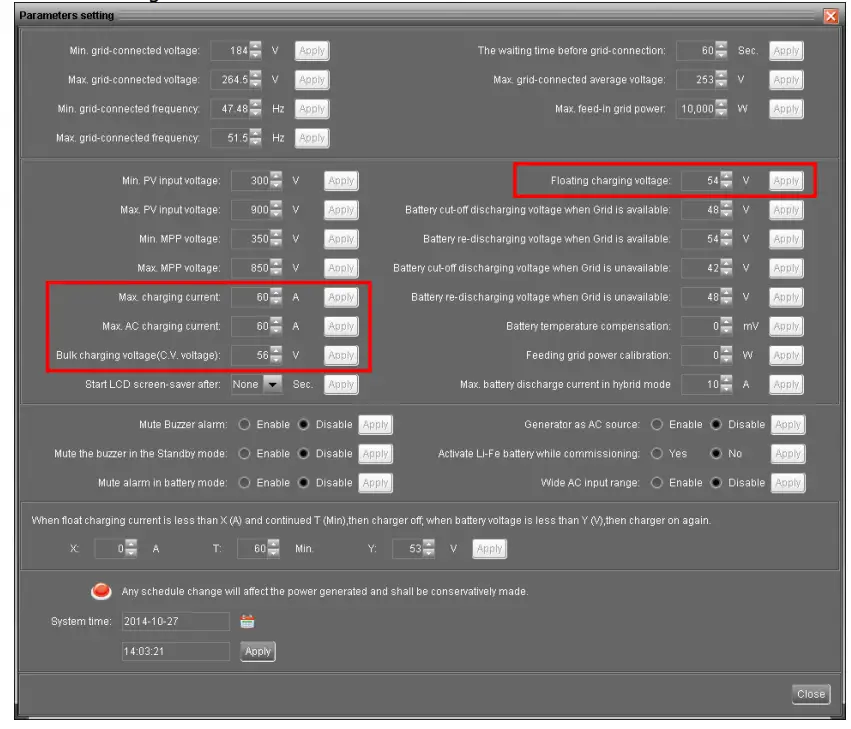
Charging Management
| Charging Parameter | Default Value | Note |
| Charging current | 60A | It can be adjusted via software from 10Amp to 200Amp. |
| Floating charging voltage (default) | 54.0 Vdc | It can be adjusted via software from 50Vac to 60Vdc. |
| Max. absorption charging voltage (default) | 56.0 Vdc | It can be adjusted via software from 50Vac to 60Vdc. |
| Battery overcharge protection | 62.0 Vdc | |
| Charging process based on default setting. 3 stages: First – max. charging voltage increases to 56V; Second- charging voltage will maintain at 56V until charging current is down to 12 Amp; Third- go to floating charging at 54V. | 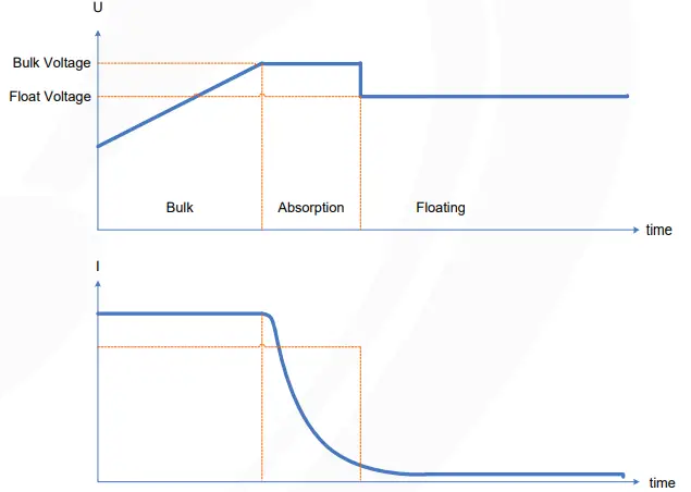 | |
This inverter can connect to battery types of sealed lead acid battery, vented battery, gel battery and lithium battery. The detail installation and maintenance explanations of the external battery pack are provided in the manufacturer’s external battery pack of manual.
If using sealed lead acid battery, please set up the max. charging current according to below formula:
The maximum charging current = Battery capacity (Ah) x 0.2
For example, if you are using 300 Ah battery, then, maximum charging current is 300 x 0.2=60 (A). Please use at least 50Ah battery because the settable minimum value of charging current is 10A. If using AGM/Gel or other types of battery, please consult with installer for the details.
Below is setting screen from software:
Maintenance & Cleaning
Check the following points to ensure proper operation of whole solar system at regular intervals.
- Ensure all connectors of this inverter are cleaned all the time.
- Before cleaning the solar panels, be sure to turn off PV DC breakers.
- Clean the solar panels, during the cool time of the day, whenever it is visibly dirty.
- Periodically inspect the system to make sure that all wires and supports are securely fastened in place.
WARNING: There are no user-replaceable parts inside of the inverter. Do not attempt to service the unit yourself.
Battery Maintenance
- Servicing of batteries should be performed or supervised by personnel knowledgeable about batteries and the required precautions.
- When replacing batteries, replace with the same type and number of batteries or battery packs.
- The following precautions should be observed when working on batteries:
a) Remove watches, rings, or other metal objects.
b) Use tools with insulated handles.
c) Wear rubber gloves and boots.
d) Do not lay tools or metal parts on top of batteries.
e) Disconnect charging source prior to connecting or disconnecting battery terminals.
f) Determine if battery is inadvertently grounded. If inadvertently grounded, remove source from ground. Contact with any part of a grounded battery can result in electrical shock. The likelihood of such shock can be reduced if such grounds are removed during installation and maintenance (applicable to equipment and remote battery supplies not having a grounded supply circuit).
CAUTION: A battery can present a risk of electrical shock and high short-circuit current.
CAUTION: Do not dispose of batteries in a fire. The batteries may explode.
CAUTION: Do not open or mutilate batteries. Released electrolyte is harmful to the skin and eyes. It may be toxic.
Trouble Shooting
When there is no information displayed in the LCD, please check if PV module/battery/grid connection is correctly connected.
NOTE: The warning and fault information can be recorded by remote monitoring software.
18-1. Warning List
There are 17 situations defined as warnings. When a warning situation occurs, ![]() icon will flash and
icon will flash and ![]() will display warning code. If there are several codes, it will display in sequences. Please contact your installer when you couldn’t handle with the warning situations.
will display warning code. If there are several codes, it will display in sequences. Please contact your installer when you couldn’t handle with the warning situations.
| Code | Warning Event | Icon (flashing) | Description |
| 01 | Line voltage high loss | | Grid voltage is too high. |
| 02 | Line voltage low loss | | Grid voltage is too low. |
| 03 | Line frequency high loss | | Grid frequency is too high. |
| 04 | Line frequency low loss | | Grid frequency is too low. |
| 05 | Line voltage loss for long time | | Grid voltage is higher than 253V. |
| 07 | Island detect | | Island operation is detected. |
| 08 | Line waveform loss | | The waveform of grid is not suitable for inverter. |
| 09 | Line phase loss | | The phase of grid is not in right sequence. |
| 10 | EPO detected | | EPO is open. |
| 11 | Overload | | Load exceeds rating value. |
| 12 | Over temperature | | The temperature is too high inside. |
| 13 | Batter voltage low | | Battery discharges to low alarm point. |
| 14 | Battery under-voltage when grid is loss | | Battery discharges to shutdown point. |
| 15 | Battery open | | Battery is unconnected or too low. |
| 16 | Battery under-voltage when grid is OK | | Battery stops discharging when the grid is OK. |
18-2. Fault Reference Codes
When a fault occurs, the icon ![]() will flash as a reminder. See below for fault codes for reference.
will flash as a reminder. See below for fault codes for reference.
| Situation | Solution | ||
| Fault Code | Fault Event | Possible cause | |
| 01 | Bus voltage over | Surge | 1. Restart the inverter. 2. If the error message still remains, please contact your installer. |
| 02 | BUS voltage under | PV or battery disconnect suddenly | 1. Restart the inverter 2. If the error message still remains, please contact your installer. |
| 03 | BUS soft start time out | Internal components failed. | Please contact your installer. |
| 04 | INV soft start time out | Internal components failed. | Please contact your installer. |
| 05 | INV over current | Surge | 1. Restart the inverter. 2. If the error message still remains, please contact your installer. |
| 06 | Over temperature | Internal temperature is too high. | 1. Check the ambient temperature and fans. 2. If the error message still remains, please contact your installer. |
| 07 | Relay fault | Internal components failed. | Please contact your installer. |
| 08 | CT sensor fault | Internal components failed. | Please contact your installer. |
| 09 | Solar input power abnormal | 1. Solar input driver damaged. 2. Solar input power is too much when voltage is more than 850V. | 1. Please check if solar input voltage is higher than 900V. 2. Please contact your installer. |
| 11 | Solar over current | Surge | 1. Restart the inverter. 2. If the error message still remains, please contact your installer. |
| 12 | GFCI fault | Leakage current excceds the limit. | 1. Check the wire and panels which may cause the leakage. 2. If the error message still remains, please contact your installer. |
| 13 | PV ISO fault | The resistance between PV and ground is too low. | |
| 14 | INV DC current over | Utility fluctuates. | 1. Restart the inverter. 2. If the error message still remains, please contact your installer. |
| 16 | GFCI sensor fault | GFCI sensor failed. | Please contact your installer. |
| 17 | DSP&MCU communication loss | Internal components failed or FW update failed | |
| 18 | DSP&MCU protocol incompatibility | DSP&MCU FW incompatibility | |
| 22 | Battery high voltage fault | Battery voltage exceeds the limit. | 1. Check the battery voltage. 2. If the error message still remains, please contact your installer. |
| 23 | Over load | The inverter is loaded with more than 110% load and time is up. | Reduced the connected load by switching off some equipment. |
| 26 | INV short | Output short circuited. | Check if wiring is connected well and remove abnormal load. |
| 27 | Fan lock | Fan failed. | Please contact your installer. |
| 32 | DCDC current over | Surge | 1. Restart the inverter. 2. If the error message still remains, please contact your installer. |
| 33 | INV voltage low | Internal components failed. | Please contact your installer. |
| 34 | INV voltage high | Internal components failed. | Please contact your installer. |
| 38 | MPPT input was shorted circuit | Internal components failed. | Please disconnect the solar input immediately and contact your installer. |
| 51 | Transformer current over | Surge | 1. Restart the inverter. 2. If the error message still remains, please contact your installer. |
| 52 | Solar1 over temperature | Internal temperature is too high. | 1. Check the ambient temperature and fans. 2. If the error message still remains, please contact your installer. |
| 53 | Solar2 over temperature |
Specifications
| MODEL | 15KW |
| RATED POWER | 15000 W |
| PV INPUT (DC) | |
| Maximum DC Power | 22500 W |
| Nominal DC Voltage | 720 VDC |
| Maximum DC Voltage | 900 VDC |
| Working DC Voltage Range | 350 VDC ~ 900 VDC |
| Start-up Voltage / Initial Feeding Voltage | 320 VDC / 350 VDC |
| MPP Voltage Range / Full Load MPP Voltage Range | 350 VDC ~ 850 VDC / 400 VDC ~ 800 VDC |
| Maximum Input Current | PV1: 37.2 A; PV2: 18.6 A |
| Max. inverter back feed current to the array | 0 A |
| GRID OUTPUT (AC) | |
| Nominal Output Voltage | 230 VAC (P-N) / 400 VAC (P-P) |
| Output Voltage Range | 184 – 265 VAC per phase |
| Output Frequency Range | 47.5 ~ 51.5 Hz or 59.3~ 60.5Hz |
| Nominal Output Current | 21.7 A per phase |
| Inrush Current/Duration | 25.5 A per phase / 20ms |
| Maximum Output Fault Current/Duration | 68 A per phase / 1ms |
| Maximum output Overcurrent Protection | 68 A per phase |
| Power Factor Range | 0.9 lead – 0.9 lag |
| AC INPUT | |
| AC Start-up Voltage | 120-140 VAC per phase |
| Auto Restart Voltage | 180 VAC per phase |
| Acceptable Input Voltage Range | 170 – 280 VAC per phase |
| Nominal Frequency | 50 Hz / 60 Hz |
| AC Input Power | 15000VA/15000W |
| Maximum AC Input Current | 40 A |
| Inrush Input Current | 40 A / 1ms |
| Generator INPUT | |
| Maximum Input Power | 16000W |
| Acceptable Input Voltage Range | 170~280 VAC per phase |
| Acceptable Input Frequency Range | 40.0 ~ 60.0 Hz |
| Maximum AC Input Current | 40 A |
| BATTERY MODE OUTPUT (AC) | |
| Nominal Output Voltage | 230 VAC (P-N) / 400 VAC (P-P) |
| Output Frequency | 50 Hz / 60 Hz (auto sensing) |
| Output Waveform | Pure sine wave |
| Output Power | 15000VA/15000W |
| Efficiency (DC to AC) | 91% |
| Transfer time | <15ms(On-grid mode to off-grid mode) |
| Transfer time in parallel mode | ≤50ms(On-grid mode to off-grid mode) |
| BATTERY & CHARGER (Lead-acid/Li-ion) | |
| DC Voltage Range | 40 – 62 VDC |
| Nominal DC Voltage | 48 VDC |
| Maximum Battery Discharging Current | 500 A |
| Maximum Charging Current | 300 A |
| GENERAL | |
| PHYSICAL | |
| Dimension, D X W X H (mm) | 820 x 650 x 224 |
| Net Weight (kgs) | 62 |
| INTERACE | |
| Communication Port | RS-232/USB |
| Intelligent Slot | Optional SNMP, Modbus and AS-400 cards available |
| ENVIRONMENT | |
| Protective Class | I |
| Ingress Protection Rating | IP20 |
| Humidity | 0 ~ 90% RH (No condensing) |
| Operating Temperature | -10 to 55°C (Power derating above 50°C) |
| Altitude | Max. 2000m* |
* Power derating 1% every 100m when altitude is over 1000m.
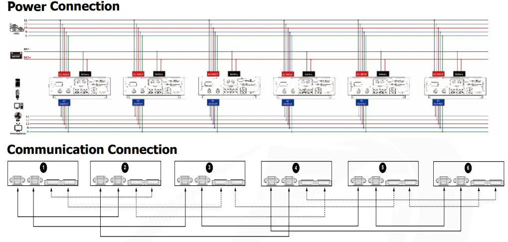
Appendix I: Parallel Installation Guide
Introduction
This inverter can be used in parallel with maximum 6 units. The supported maximum output power is 90KW/90KVA.
Warning: Please make sure the output neutral of each inverter is always connected when they are configured in parallel working, or it will damage the inverter.
Warning: Please makes sure the solar input of each inverter is independent, or it will damage the inverter.
Parallel cable
You will find the following items in the package:
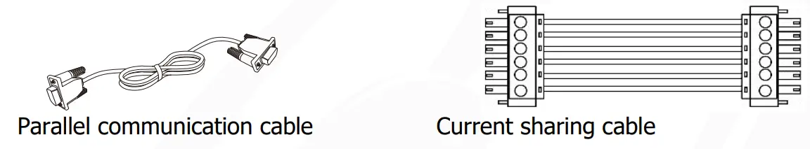
Overview
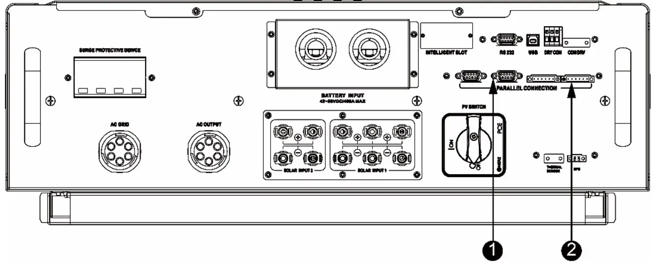
- Parallel communication port
- Current sharing port
Mounting the Unit
When installing multiple units, please follow below chart.
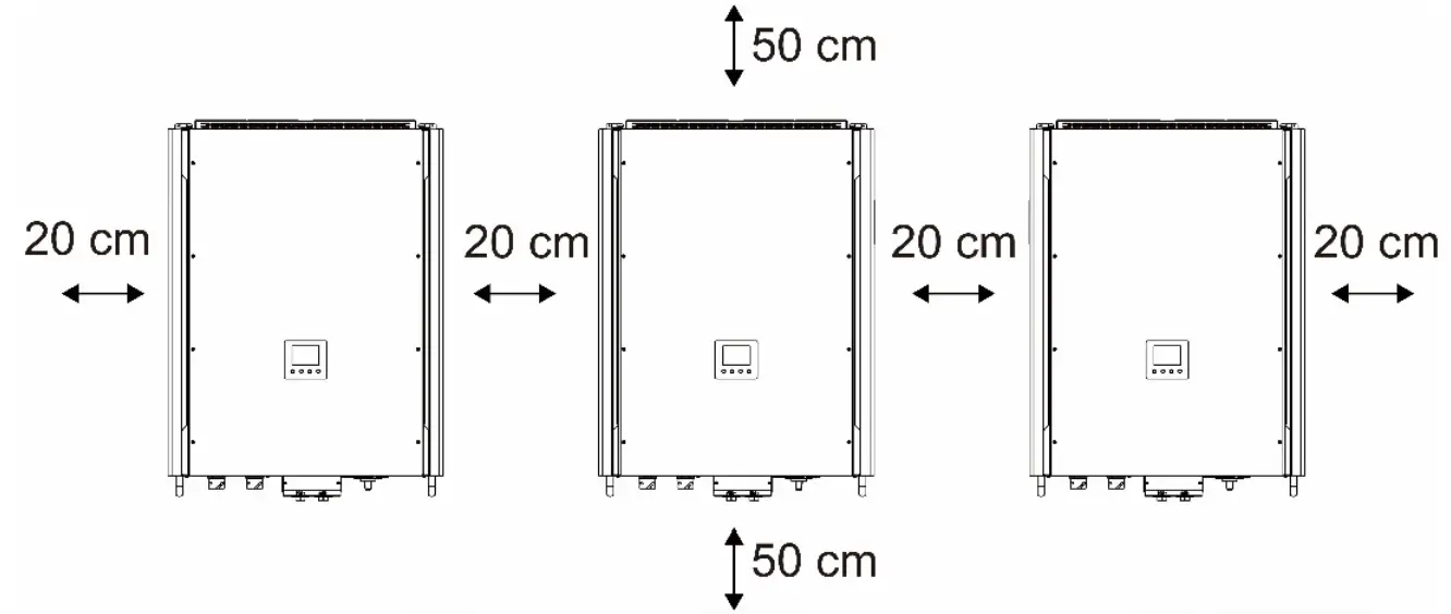
NOTE: For proper air circulation to dissipate heat, it’s necessary to allow a clearance of approx. 20 cm to the side and approx. 50 cm above and below the unit. Be sure to install each unit in the same level.
Wiring Connection
The cable size of each inverter is shown as below:
Recommended battery cable and terminal size for each inverter:
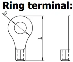
| Model | Wire Size | Ring Terminal | Torque value | ||
| Cable mm2 | Dimensions | ||||
| D (mm) | L (mm) | ||||
| 15KW | 2*3/0 | 170 | 8.4 | 54.2 | 7~12 Nm |
WARNING: Be sure the length of all battery cables is the same. Otherwise, there will be voltage difference between inverter and battery to cause parallel inverters not working.
Recommended AC input and output cable size for each inverter:
| Model | AWG no. | Conductor cross- section | Torque |
| 15KW | 10~8 AWG | 5.5~10 mm2 | 1.4~1.6Nm |
You need to connect the cables of each inverter together. Take the battery cables for example. You need to use a connector or bus-bar as a joint to connect the battery cables together, and then connect to the battery terminal. The cable size used from joint to battery should be X times cable size in the tables above. “X” indicates the number of inverters connected in parallel.
Regarding cable size of AC input and output, please also follow the same principle.
CAUTION!! Please install a breaker at the battery side. This will ensure the inverter can be securely disconnected during maintenance and fully protected from overcurrent of battery.
Recommended breaker specification of battery for each inverter:
| Model | One unit* |
| 15KW | 450A/60VDC |
*If you want to use only one breaker at the battery side for the whole system, the rating of the breaker should be X times current of one unit. “X” indicates the number of inverters connected in parallel.
Recommended battery capacity
| Inverter parallel numbers | 2 | 3 | 4 | 5 | 6 |
| Battery Capacity | 800AH | 1200AH | 1600AH | 2000AH | 2400AH |
CAUTION! Please follow the battery charging current and voltage from battery spec to choose the suitable battery. The wrong charging parameters will reduce the battery lifecycle sharply.
Approximate back-up time table
| Load (W) | Backup Time @ 48Vdc 800Ah (min) | Backup Time @ 48Vdc 1200Ah (min) | Backup Time @ 48Vdc 1600Ah (min) | Backup Time @ 48Vdc 2000Ah (min) | Backup Time @ 48Vdc 2400Ah (min) |
| 5,000 | 240 | 360 | 480 | 600 | 720 |
| 10,000 | 112 | 168 | 224 | 280 | 336 |
| 15,000 | 60 | 90 | 120 | 150 | 180 |
| 20,000 | 40 | 60 | 80 | 100 | 120 |
| 25,000 | 20 | 30 | 40 | 50 | 60 |
| 30,000 | 16 | 24 | 32 | 40 | 48 |
PV Connection
Please refer to user manual of single unit for PV Connection.
CAUTION: Each inverter should connect to PV modules separately.
Inverters Configuration
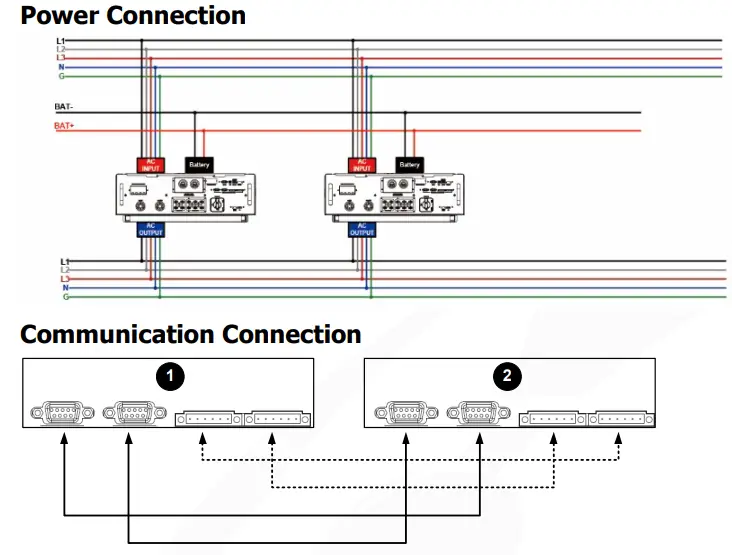
Two inverters in parallel:
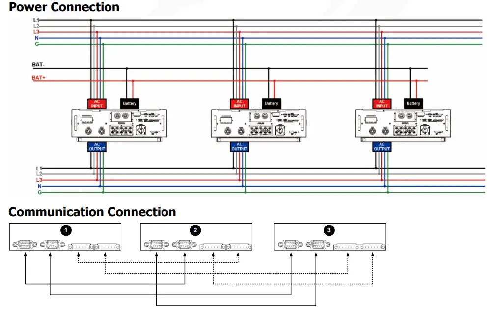
Three inverters in parallel:
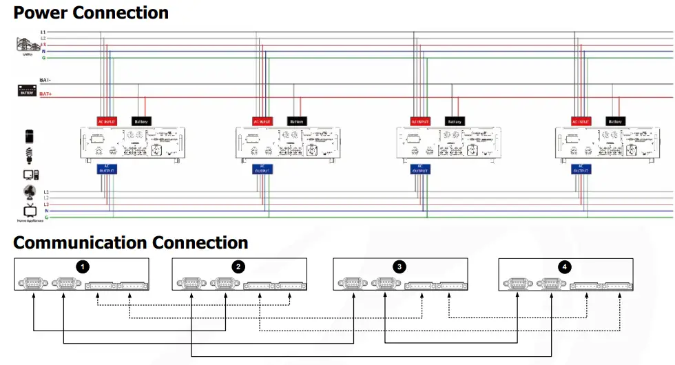
Four inverters in parallel:
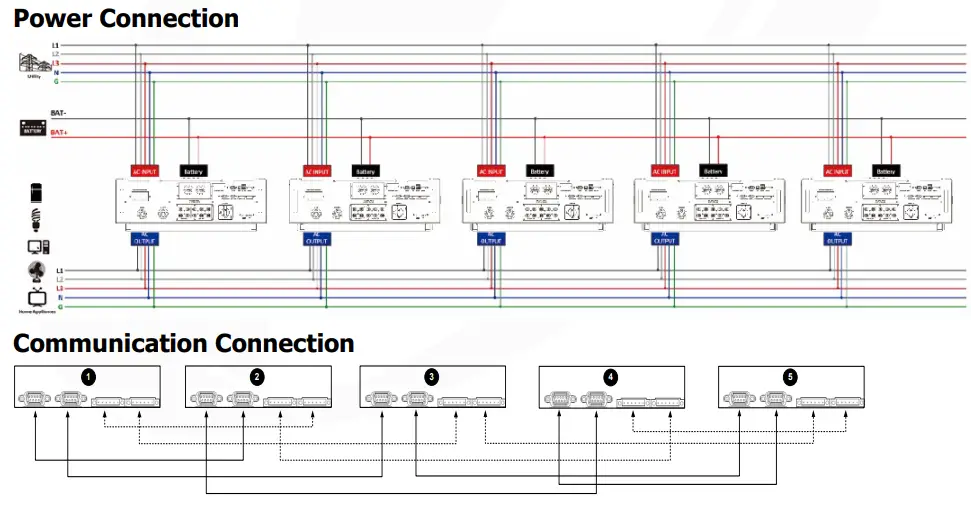
Five inverters in parallel:
Six inverters in parallel:
Setting and LCD Display
Setting Program:
The parallel function setting is only available by SolarPower. Please install SolarPower in your PC first.
For setting, you can set the inverter one by one through RS232 or USB port.
But we suggest to use SNMP or Modbus card to combine the system as a centralized monitoring system. Then, you can use “SYNC” function to set all the inverters at the same time. If using SNMP or Modbus card to set up program, the bundled software is SolarPower Pro.
- Use SNMP card to synchronize the parameters:
Each inverter should be installed one SNMP card. Make sure all of the SNMP cards are connected to the router as a LAN.
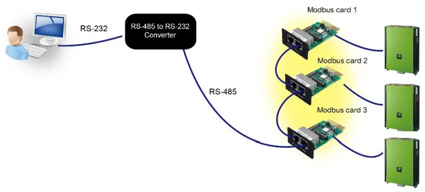
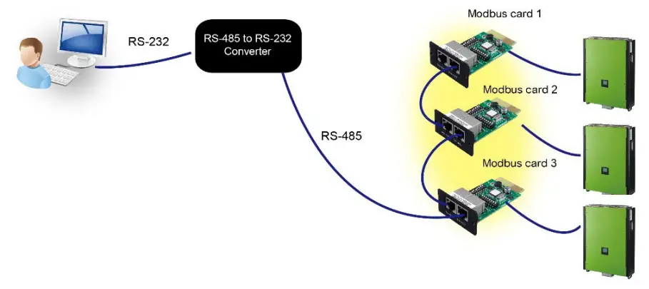
- Use Modbus card to synchronize the parameters:
Each inverter should be installed one Modbus card. Make sure all of the Modbus cards are connected to each other and one of the Modbus cards is connected to the computer by RS-485/RS232 converter.
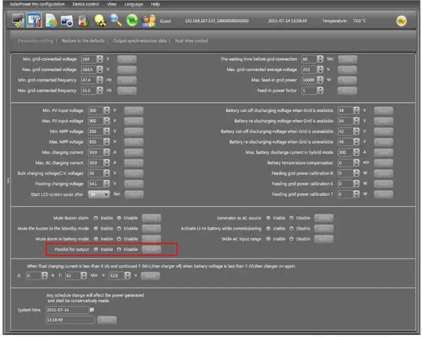
Launch SolarPowerPro in computer and select Device Control >> Parameter Setting >> Parallel output. Two options: Enable or Disable.
If you want to use parallel function, please choose “Enable” and press “ ![]() ” button. Then, “
” button. Then, “ ![]() ” button will be shown is the screen. Please be sure to click “
” button will be shown is the screen. Please be sure to click “ ![]() ” button before clicking “
” button before clicking “ ![]() ” button.
” button.
There is a “Sync” button in each parameter setting. When “Sync” is clicked and “Apply” is pressed, this new setting will be applied to all inverters. If not, this setting is only effected in current inverter you choose.
Note: Without centralized monitoring system, “Sync” function is not effective. Then, you have to set up the inverter one by one through serial communication port.
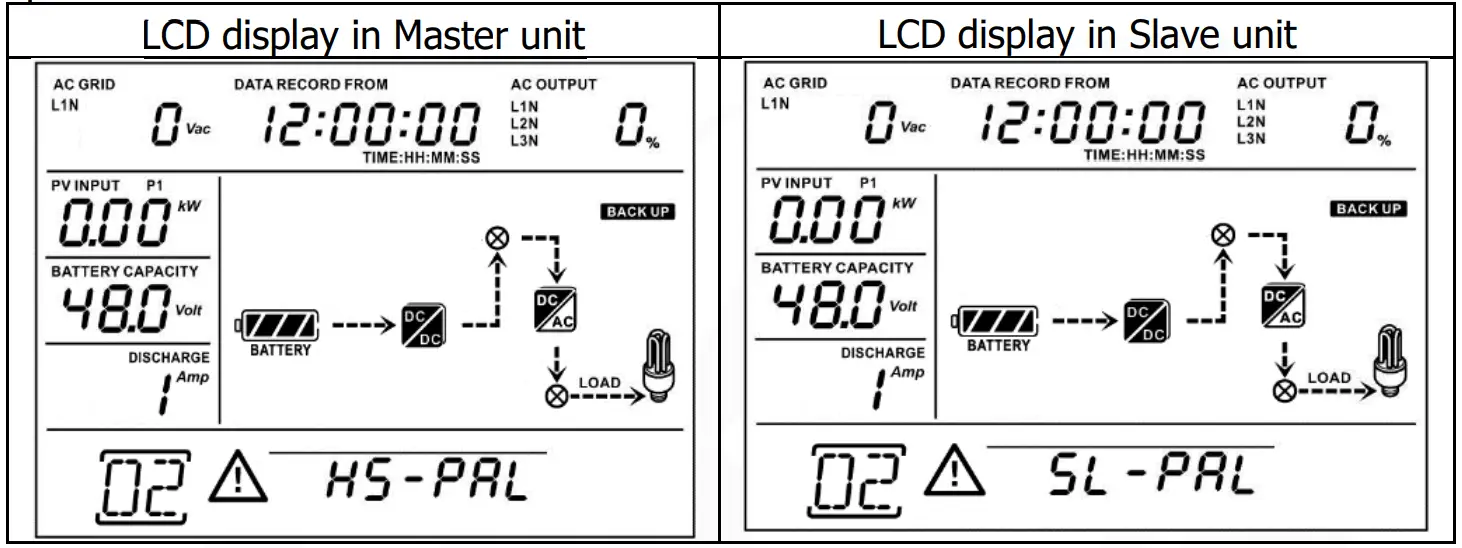
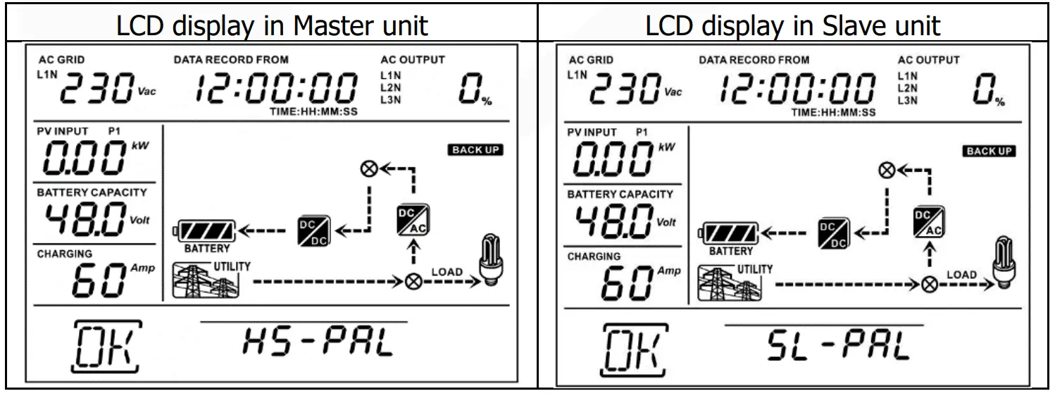
Parallel for output: Enable
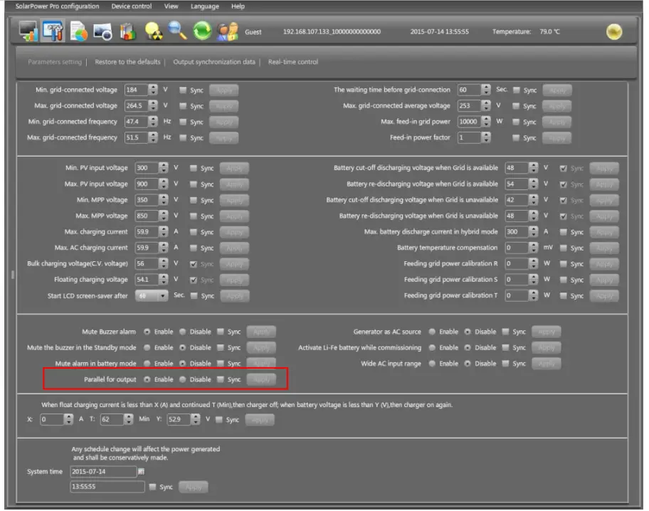
Parallel for output: Disable
Fault code display:
| Fault Code | Fault Event | Icon on |
| 60 | Power feedback protection | 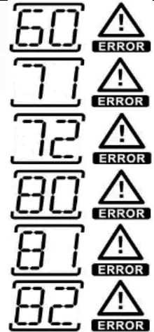 |
| 71 | Firmware version inconsistent | |
| 72 | Current sharing fault | |
| 80 | CAN fault | |
| 81 | Host loss | |
| 82 | Synchronization loss |
Commissioning
Step 1: Check the following requirements before commissioning:
- Correct wire connection.
- Ensure all breakers in Line wires of load side are open and each Neutral wire of each unit is connected together.
Step 2: Turn on each unit and set “enable parallel for output” on SolarPower or SolarPower Pro. And then, shut down all units.
Step 3: Turn on each unit.
NOTE: Master and slave units are randomly defined. Warning 02 is AC GRID voltage low.
Step 4: Switch on all AC breakers of Line wires in AC input. It’s better to have all inverters connect to utility at the same time. If not, it will display fault 82 in followingorder inverters.
However, these inverters will automatically restart.
If detecting AC connection, they will work normally.
Step 5: If there is no more fault alarm, the parallel system is completely installed.
Step 6: Please switch on all breakers of Line wires in load side. This system will start to provide power to the load.
Trouble shooting
| Situation | Solution | |
| Fault Code | Fault Event Description | |
| 60 | Current feedback into the inverter is detected. |
|
| 71 | The firmware version of each inverter is not the same. |
|
| 72 | The output current of each inverter is different. |
|
| 80 | CAN data loss |
|
| 81 | Host data loss | |
| 82 | Synchronization data loss | |


 Three Phase Solar Inverter User Manual")


