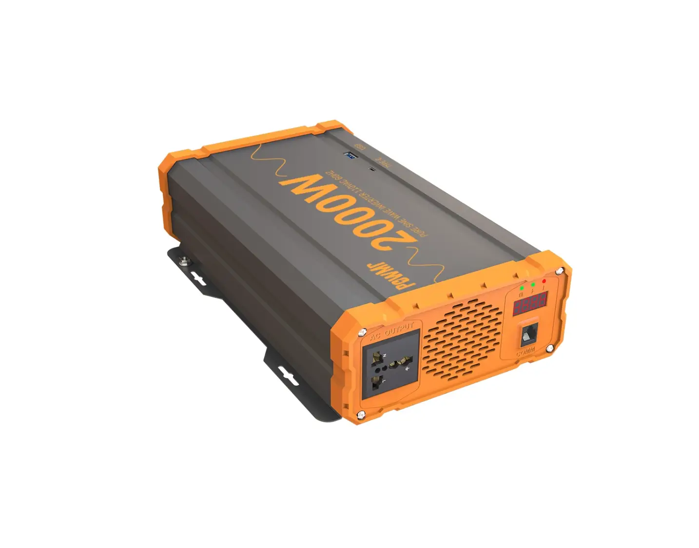
PowMr POW-LV 2000W 12VDC 110VAC Solar Off Grid Power Inverter
Inverter Safety Instruction
- Installation and wiring must comply with the Local and National Electric Codes {NEC) and must be done by a certified technician.
- Read all of the instructions and cautions in the manual before beginning the installation.
- There are no serviceable parts for this inverter. Do NOT disassemble or attempt to repair the inverter.
- Please confirm the rated battery voltage before installation. The binverters are suitable for 12V Battery Banks ONLY.
- Please confirm the positive and negative poles of the battery and the machine (red for positive pole, black for negative pole). Damage to the inverters due to reverse polarity is NOT covered by warranty.
- Please install the machine in a well ventilated place to avoid water inflow.
- After the inverter works continuously, the temperature of the case is high, which is a normal phenomenon.
- Make sure all connections going into and from the inverter are tight. There may be sparks when making connections, therefore, make sure there are not flammable materials or gases near installation.
- ALWAYS make sure inverter is in OFF position and disconnect all AC and DC connecting when working on any circuit associated with the inverter.
- NEVER connect the AC output of the unit directly to an Electrical Breaker Panel/ Load Centre which is also fed from the utility power/ generator.
- Be careful when touching bare terminals of capacitors as they may retain high lethal voltages even after power is removed
Battery Safety Instruction
- Do NOT let the positive(+) and negative(-) terminals of the battery touch each other.
- Use only sealed lead-acid, flooded, or gel batteries which must be deep cycle.
- Explosive battery gases may be present while charging. Be certain there is enough ventilation to release the gases.
- Be careful when working with large lead acid batteries. Wear eye protection and have fresh water available in case there is contact with the battery acid.
- Over-charging and excessive gas precipitation may damage the battery plates and activate material shedding on them. Too high of an equalizing charge or too long of one may cause damage.
- Please carefully review the specific requirements of the battery used in the system. Product
Product Features
- Pure sine wave. Clean power for safe operation of sensitive electronics
- Maximum efficiency 92 %.
- Intelligent fan speed regulation: start to work when the load is greater than 600w, and the fan speed will be controlled according to the load and the internal temperature.
- Protection function: input low voltage protection, input high voltage protection, overload protection, short circuit output protection, over temperature protection.
- Easy-to-read LED indicator display
- Excellent Surge Rating : 2x the Power Rating
- Build-in 3.0 QC USB port
- Application: home, office, vehicle, yacht and other occasion.
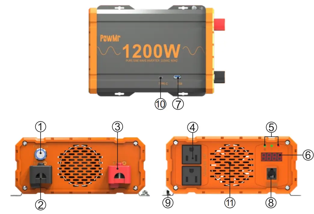
| 1 | NO/OFF Switch |
| 2 | Negative Terminal |
| 3 | Positive Terminal |
| 4 | AC Outlets |
| 5 | LED Indicators |
| 6 | LED Display |
| 7 | USB Power Port |
| 8 | Remote Switch Connection |
| 9 | Ground Terminal |
| 10 | TYPE-C Port |
| 11 | Cooling Fans |
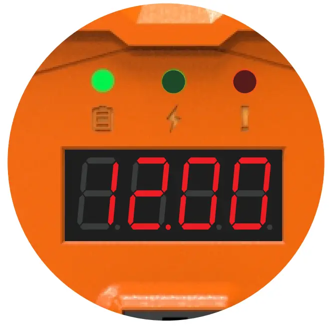
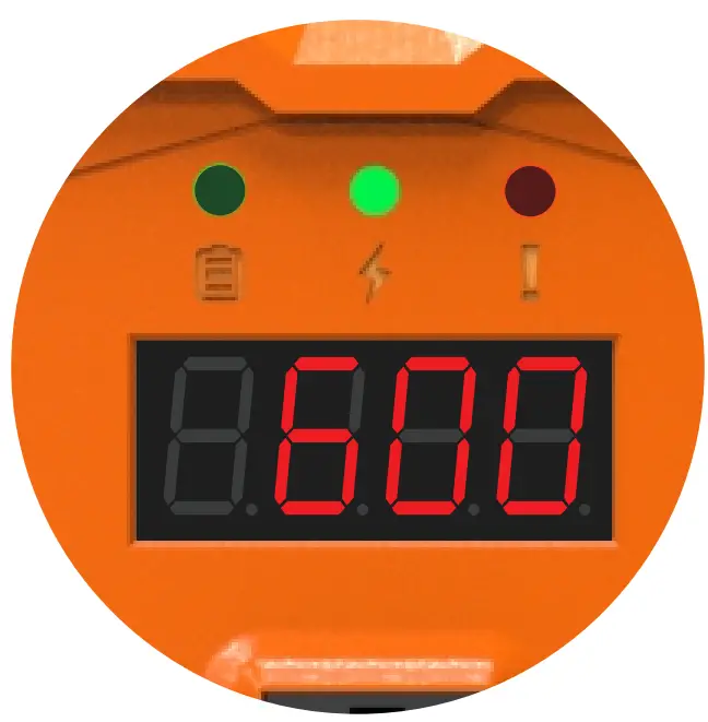
Indicator Light Description
- The “
 ” indicator light is on, indicating that the content displayed by the nixie tube is the battery voltage(V);
- The “
 ‘ indicator light is on, indicating that the content displayed on the nixie tube is the output power(W);
- The”” indicator light is on, indicating that the content displayed by the digital tube is the fa
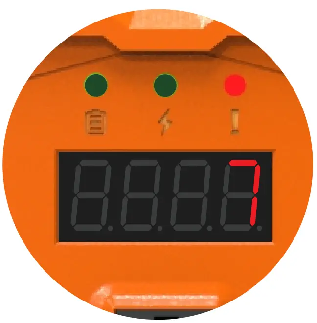
Fault code
| Fault code | Description | Solution |
| 1 | BUS soft start failed | Restart the inverter |
| 2 | BUS voltage is too high | Restart the inverter |
| 3 | BUS voltage is too low | Restart the inverter |
| 4 | Inverter start failure | Restart the inverter and check the battery connections |
| 5 | Inverter high voltage | Restart the inverter |
| 6 | Inverter low voltage | Restart the inverter |
| 7 | Output short circuit | Check the load status and disconnect the load and restart the inverter |
| 8 | Battery over voltage | Check battery voltage to ensure it is within operating range |
| 9 | Battery low voltage | Check battery voltage to ensure it is within operating range |
| 10 | Over temperature | Check the fan status, Ensure that the air inlet and outlet of the inverter are not blocked and turn off the inverter for 10 minutes. |
| 11 | Overload | Check that the inverter load does not exceed the rated power |
Installation Instruction
- Make sure inverter is in the off position before connecting anything.
- Do not over-torque or over tighten the terminals. This could potentially damage the unit.
- Refer to the technical specifications for max wire sizes on the inverter and for the maximum amperage going through wires.
- Never install the inverter in a sealed enclosure with flooded batteries. Gas can accumulate and there is a risk of explosion.
- Please install the inverter in a well ventilated place to avoid water inflow.
- Do not install the inverter in the same compartment as the battery bank because it could serve as a potential fire hazard.
- Limiting electromagnetic interference {EMI) – ensure the inverter is firmly grounded to a building, vehicle, or earth grounded. Keep the inverter away from EMI receptors such as TVs, radios, and other audio/visual electronics to prevent damage/interference to the equipment.
- The inverter should never be mounted vertically on a vertical surface since it would present a hazard for the fan opening which is crucial for cooling the inverter.
Grounding Instruction
Pure Sine Wave inverters come equipped with a grounding lug to appropriately ground to earth or to another designated ground (for example, a metal frame of an RV). The connections to ground must be tight and against bare metal. Whether using the inverter in a mobile application, such as an RV, or in a building, grounding is highly recommended. The recommended wire size for grounding is 10 AWG insulated copper strand wire. For more information regarding grounding, users and/or installers must consult with the Local and National Electric Codes {NEC) for more specific grounding regulations and suggestions as they can change per scenario.
DC Side Connection
- Flip inverter power to OFF position (on AC side)
- Remove Cap, then unscrew inverter terminals and connect battery connections. Then tighten.
NOTE:
- The Pure Sine Wave Inverters are suitable for 12V battery bank systems ONLY. Not following the minimum DC requirement will cause irreversible damage to the unit.
- Be careful of the positive and negative poles. Reversing the poles might cause permanent damage to the inverter. It will surely blow the internal fuse.
- Damage to the inverters due to reverse polarity is NOT covered by warranty.
- The input terminals of the inverters have large capacitors connected to them. Once a positive and negative wire are connected to the terminals, it will complete the circuit, and commence drawing a heavy current momentarily. As a result, there may be a sparking occurring even if the inverter is in the off position. To minimize sparking, it is recommended that the user have the appropriate size wire feeding into the inverters and/or install an external fuse leading into the inverter.
AC Side Operation
- Connect electronic devices to electrical socket(s) on inverter. Flip inverter power to ON position (on AC side)
- When finished, switch AC devices off FIRST, then turn off inverter switch
NOTE:
- Avoid switching on the inverter with the load (electronic devices) already switched on. This may trigger an overload since some electronic devices have an initial high power surge to start.
- When switching off the inverter, turn off the electronic devices first. Although the inverter is off, the capacitors will still have a charge, so the DC and AC terminals must be disconnected if altering the circuitry.
Product Parameters
| Model | POW-LV1.2K-12V | POW-LV2K-12V | |
| Input | Rated Input Voltage | 12V | 12V |
| Rated Current | 112A | 210A | |
| Maximum Efficiency | 92% | 92% | |
| Battery Type | Lead acid/Lithium battery | ||
| AC Output | Rated Power | 1200W | 2000W |
| AC Voltage | 110V | ||
| Frequency | 60Hz | ||
| Waveform | PURE SINE WAVE | ||
| Input Protection | Battery Low Alarm | 10.5V±0.5V | |
| Battery Low Recovery | 11.0V±O.SV | ||
| Battery Low Shutdown | 10.0V±O.SV | ||
| Battery High Alarm | 15.0V±O.SV | ||
| Battery Low Recovery | 14.5V±0.5V | ||
| Battery High Shutdown | 15.5V±0.5V | ||
| Output Protection | Output Short Circuit Protection | After the fault is eliminated,it can be rebooted | |
| Overload Protection | 110%,s;Load<125%,1 minute shutdown; 125%,s;Load<l50%,30s shutdown; 150%,s;Load,shut down immediately; | ||
| Over- temperature protection | Heat dissipation temperature> 90°C, protection Heat dissipation temperature> 90°C, | ||
| Operating Enviroment | Operating Temperature | o-40°c | |
| Humidity | 0-80% | ||
| Other | Dimension | 265x181x81(mm) | 315x181x81(mm) |
| Remote Control Switch Interface | Standard configuration | ||
| USB | QC3.0(18W Max) | ||
| AC Output Sockets | 2 | 2 | |
| Model | POW-LV1.2K-24V | POW-LV2K-24V | |
| Input | Rated Input Voltage | 24V | 24V |
| Rated Current | 56A | 105A | |
| Maximum Eff i ci en cy | 92% | 92% | |
| Battery Type | Lead acid/Lithium battery | ||
| AC Output | Rated Power | 1200W | 2000W |
| AC Voltage | 110V | ||
| Frequency | 60Hz | ||
| Wave form | PURE SINE WAVE | ||
| Input Protection | Battery Low Alarm | 21.0V±0.SV | |
| Battery Low Recovery | 22.0V+0.SV | ||
| Battery Low Shutdown | 20.0 V+ 0.SV | ||
| Battery High Alarm | 30.0V+0.SV | ||
| Battery High Alarm Recovery | 29.0V± 0.SV | ||
| Battery High Shutdown | 31.0V+ 0.SV | ||
| Output Protection | Output Short Circuit Protection | After the fault is eliminated, it can be rebooted | |
| Overload Protection | 110%”sload<125%,1 minute shutdown; 125%”sload<l50%,30s shutdown; 150%”sload,shut down immediately; | ||
| Over- temperature protection | Heat dissipation temperature> 90°C, Over-temperature protection | ||
| Operating Enviroment | Operating Temperature | O-40°C | |
| Humidity | 0-80% | ||
| Other | Dimension | 265x181x81(mm) | 315x181x81(mm) |
| Remote Control Switch Interface | Standard configuration | ||
| USB | QC3.0(18W Max) | ||
| AC Output Sockets | 2 | 2 | |
Optional Accessory
| Inverter Model | Gauge |
| 1200W | 4AWG 3ft |
| 2000W | 2*4AWG3ft |
REMOTE
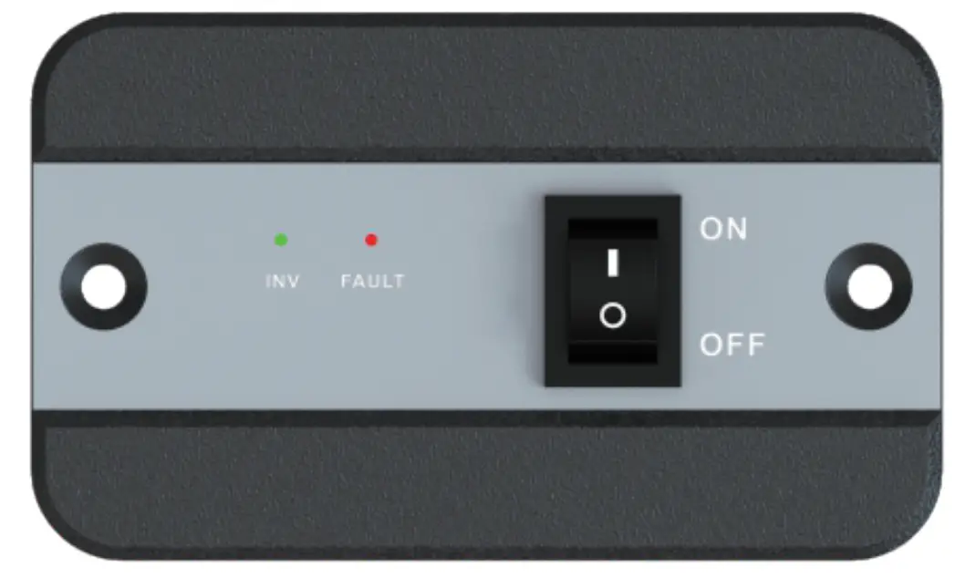
| List dimensions | 2.875×2.3125×0.9375in,73×58.7×23.8mm |
| Thickne ss | 0625in,1.5mm |
| Wire length | Approx19.8ft |
SHENZHEN HEHEJIN INDUSTRIAL CO.,LTD Tel/
Tel/Fax: +86 755-28219903
Email: [email protected]
Web: www.powmr.com
Add: Hengyang Street, Logging District, Shenzhen, Guangdong, China