![]()
Force Series Solar Inverter
User Manual
Force Series Inverter
Important Notes
1.1 Scope
This manual describes the assembly, installation, commissioning, maintenance and troubleshooting of the following model(s) of
Energizer products:
| Force 3S Force 5S | Force 3.6S Force 6S | Force 4.6S |
Note: Please keep this manual where it will be accessible at all times. *India
1.2 Target Group
This manual is for qualified personnel only. The tasks described in this manual will need to be performed by professional, suitably qualified technicians only.
1.3 Symbols Used
The following types of safety instructions and general information appear in this document as described below:
| Danger! ‘Danger’ indicates a hazardous situation which, if not avoided, will result in death or serious injury. | |
| Warning! ‘Warning” indicates a hazardous situation which, it not avoided, could result in death or serious injury. | |
| Caution! `Caution” indicates a hazardous situation which, if not avoided. could result in minor or moderate injury. | |
 | Note! ‘Note’ provides Important tips and guidance. |
1.4 Symbols Explanation
This section explains the symbols shown on the inverter and on the type label:
| Symbols | Explanation |
 | Symbol Explanation CE mark. The inverter complies with the requirements of the applicable CE guidelines. |
| This mark indicates compound UK product safety certification requirements. | |
| Beware of hot surface. The inverter can become hot during operation. Avoid contact during operation. | |
| Danger of high voltages. Danger to life due to high voltages in the inverter! | |
| Danger. Risk of electric shock! | |
 | Danger to life due to high voltage. There is residual voltage in the inverter which needs 5 min to discharge. Wait 5 min before you open the upper lid or the DC lid. |
| Read the manual. | |
| Product should not be disposed as household waste. | |
| PE conductor terminal |
Safety
2.1 Appropriate Usage
This series inverter is designed and tested in accordance with international safety requirements. However, certain safety precautions must be taken when installing and operating this inverter. The installer must read and follow all instructions, cautions and warnings in this installation manual.
- All operations including transport, installation, start-up and maintenance, must be carried out by qualified, trained personnel.
- The electrical installation & maintenance of the inverter shall be conducted by a licensed electrician and shall comply with local wiring rules and regulations.
- Before installation, check the unit to ensure it is free of any transport or handling damage, which could affect insulation integrity or safety clearances. Choose the installation location carefully and adhere to specified cooling requirements. Unauthorized removal of necessary protections, improper use, incorrect installation and operation may lead to serious safety and shock hazards or equipment damage.
- Before connecting the inverter to the power distribution grid, contact the local power distribution grid company to get appropriate approvals. This connection must be made only by qualified technical personnel.
- Do not install the equipment in adverse environmental conditions such as in close proximity to flammable or explosive substances; in a corrosive environment; where there is exposure to extreme high or low temperatures; or where humidity is high.
- Do not use the equipment when the safety devices do not work or are disabled.
- Use personal protective equipment, including gloves and eye protection during the installation.
- Inform the manufacturer about non-standard installation conditions.
- Do not use the equipment if any operating anomalies are found. Avoid temporary repairs.
- All repairs should be carried out using only approved spare parts, which must be installed in accordance with their intended use and by a licensed contractor or authorized service representative.
- Liabilities arising from commercial components are delegated to their respective manufacturers.
- Any time the inverter has been disconnected from the public network, please be extremely cautious as some components can retain charge sufficient to create a shock hazard. Prior to touching any part of the inverter please ensure surfaces and equipment are under touch safe temperatures and voltage potentials before proceeding.
- This product was not tested to section 5 of AS/NZS 4777.2:2020, and is not to be used in multiple inverter combinations without additional measures taken within the installation to ensure continued compliance to requirements.
2.2 PE Connection and Leakage Current
PV System Residual Current Factors
- In every PV installation, several elements contribute to the current leakage to protective earth (PE). these elements can be divided into two main types.
- Capacitive discharge current – Discharge current is generated mainly by the parasitic capacitance of the PV modules to PE. The module type, the environmental conditions (rain, humidity) and even the distance of the modules from the roof can effect the discharge current. Other factors that may contribute to the parasitic capacitance are the inverter’s internal capacitance to PE and external protection elements such as lighting protection.
- During operation, the DC bus is connected to the alternating current grid via the inverter. Thus, a portion of the alternating voltage amplitude arrives at the DC bus. The fluctuating voltage constantly changes the charge state of the parasitic PV capacitor (i.e capacitance to PE). This is associated with a displacement current, which is proportional to the capacitance and the applied voltage amplitude.
- Residual current – if there is a fault, such as defective insulation, where an energized cable comes into contact with a grounded
person, an additional current flows, known as a residual current.
Residual Current Device (RCD)
- All Energizer inverters incorporate a certified internal RCD (Residual Current Device) to protect against possible electrocution in case of a malfunction of the PV array, cables or inverter (DC). The RCD in the Energizer inverter can detect leakage on the DC side. There are 2 trip thresholds for the RCD as required by the DIN VDE 0126-1-1 standard. A low threshold is used to protect against rapid changes in leakage typical of direct contact by people. A higher threshold is used for slowly rising leakage currents, to limit the current in grounding conductors for the safety. The default value for higher speed personal protection is 30mA, and 300mA per unit for lower speed fire safety.
Installation and Selection of an External RCD device
- An external RCD is required in some countries. The installer must check which type of RCD is required by the specific local electric codes. Installation of an RCD must always be conducted in accordance with local codes and standards. Energizer recommends the use of a type-A RCD. Unless a lower value is required by the specific local electric codes, Energizer suggests an RCD value between 100mA and 300mA.
- In installations where the local electric code requires an RCD with a lower leakage setting, the discharge current might result in nuisance tripping of the external RCD. The following steps are recommended to avoid nuisance tripping of the external RCD:
- Selecting the appropriate RCD is important for correct operation of the installation. An RCD with a rating of 30mA may actually trip at a leakage as 15mA (according to IEC 61008). High quality RCDs will typically trip at a value closer to their rating.
- Configure the trip current of the inverter’ internal RCD to a lower value than the trip current of the external RCD. The internal RCD will trip if the current is higher than the allowed current, but because the internal inverter RCD automatically resets when the residual currents are low it saves the manual reset.
2.3 Surge Protection Devices (SPDs) for PV Installation
WARNING!
Over-voltage protection with surge arresters should be provided when the PV power system is installed. The grid connected inverter is not fitted with SPDs in both PV input side and mains side Lightning will cause damage either from a direct strike or from surges due to a nearby strike. Induced surges are the most likely cause of lightning damage in majority or installations, especially in rural areas where electricity is usually provided by long overhead lines. Surges may impact on both the PV array conduction and the AC cables leading to the building. Specialists in lightning protection should be consulted during the end use application. Using appropriate external lightning protection, the effect of a direct lightning strike into a building can be mitigated in a controlled way, and the lightning current can be discharged into the ground.
Installation of SPDs to protect the inverter against mechanical damage and excessive stress include a surge arrester in case of a building with external lightning protection system (LPS) when separation distance is kept. To protect the DC system, surge suppression device (SPD type2) should be fitted at the inverter end of the DC cabling and at the array located between the inverter and the PV generator, if the voltage protection level (VP) of the surge arresters is greater than 1100V, an additional SPD type 3 is required for surge protection for electrical devices.
To protect the AC system, surge suppression devices (SPD type2) should be fitted at the main incoming point of AC supply (at the consumer’s cutout), located between the inverter and the meter/distribution system; SPD (test impulse D1) for signal line according to EN 61632-1. All DC cables should be installed to provide as short a run as possible, and positive and negative cables of the string or main DC supply should be bundled together.
Avoiding the creation of loops in the system. This requirement for short runs and bundling includes any associated earth bundling conductors. Spark gap devices are not suitable to be used in DC circuits once conducting; they won’t stop conducting until the voltage across their terminals is typically below 30 volts.
About Product
3.1 About Inverter
This series inverters cover 3kW systems up to 6kW and are integrated with 2 MPP trackers with high efficiency and reliability.
3.2 Basic Features
- Advanced DSP control technology.
- Utilizes the latest high-efficiency power component.
- Optimal MPPT technology.
- Two independent MPP trackers.
- Wide MPPT input range.
- Advanced anti-islanding solutions.
- IP65 protection level.
- Max. Efficiency up to 97.4%. EU efficiency up to 96.8%. THD<3%.
- Safety & Reliability: Transformer less design with software and hardware protection.
- Export limitation (CT/Meter/DRM0/ESTOP).
- Power factor regulation. Friendly HMI.
- LED status indications.
- LCD display technical data, human-machine interaction through touch key.
- PC remote control.
- Upgrade through USB interface.
3.3 Terminals Introduction
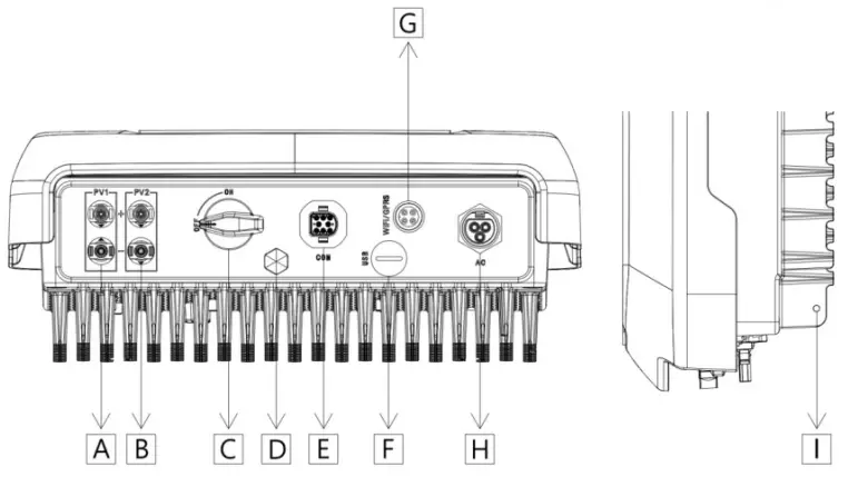
| Item | Description |
| A | DC Connector |
| B | DC Connector |
| C | DC Switch (Optional)* |
| D | Waterproof Lock Valve |
| E | Communication Port |
| F | USB Port (For Upgrade) |
| G | WiFi/GPRS/LAN (Optional) |
| H | AC Connector |
| I | Grounding Screw |
Note: Only authorized personnel are permitted to set the connection.
*: Inbuilt DC Switch included in Australia market.
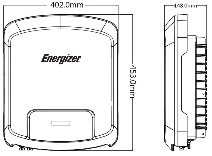
3.4 Dimensions
Technical Data
4.1 DC Input
| Model | Force 3S | Force 3.6S | Force 4.6S | Force 5S | Force 6S |
| Max. recommended DC power [W] | 4500 | 5400 | 6900 | 7500 | 9000 |
| Max. DC voltage [V] | 600 | 600 | 600 | 600 | 600 |
| Nominal DC operating voltage[V] | 360 | 360 | 360 | 360 | 360 |
| MPPT voltage range [V] | 80-550 | 80-550 | 80-550 | 80-550 | 80-550 |
| MPPT voltage range @ full load [V] | 130-550 | 150-550 | 200-550 | 210-550 | 250-550 |
| Max. input current (input A/input B) [A] | 14/14 | 14/14 | 14/14 | 14/14 | 14/14 |
| Max. short circuit current (input A/input B) [A] | 18/18 | 18/18 | 18/18 | 18/18 | 18/18 |
| Start output voltage [V] | 120 | 120 | 120 | 120 | 120 |
| No. of MPP trackers | 2 | 2 | 2 | 2 | 2 |
| Strings per MPP tracker | 1 | 1 | 1 | 1 | 1 |
| Max.inverter backed current to the array [mA] | 0 | ||||
| DC switch | Optional* | ||||
*: India market only. **: Inbuilt DC Switch included in Australia market.
4.2 AC Output
| Model | Force 3S | Force 3.6S | Force 4.6S | Force 5S | Force 6S |
| Rated output power [W] | 3000 | 3600 | 4600 | 5000 | 6000 |
| Max. apparent AC power [VA] | 3300 | 3960/3600[1] | 5060/4600[2] | 5500/5000[3] | 6000 |
| Rated grid voltage and range [V] | 220/230 | ||||
| Rated AC frequency and range [Hz] | 50/60, ±5 | ||||
| AC nominal current [A] | 13.0 | 15.7 | 20.0 | 21.7 | 26.1/27.3[4] |
| Max. output fault current [A] | 14.3 | 17.2/15.7[1] | 22/20[2] | 23.9/21.7[3] | 26.1/27.3[4] |
| Maximum output over current protection [A] | 58 | ||||
| Inrush current [A] | 7.9A@50us | ||||
| Rated apparent power [VA] | 3000 | 3600 | 4600 | 5000 | 6000 |
| Maximum output fault current [A] | 167A@10us | ||||
| THD | <3% | ||||
| Displacement power factor | 1 (Adjustable from 0.8 leading to 0.8 lagging) | ||||
| Feed in phase | Single-phase | ||||
| Over voltage category | PV: OVC II Mains: OVC III | ||||
| Active anti-islanding method | frequency shift | ||||
[1]3600 for G98, 3960 for other country
[2]4600 for VDE-AR-N 4105 and Belgium, 5060 for other country
[3]5000 for Australia and Belgium, 5500 for other country ; [4]27.3A for Brazil only
4.3 Efficiency, Safety and Protection
| Model | Force 3S | Force 3.6S | Force 4.6S | Force 5S | Force 6S |
| Max. MPPT efficiency | 99.00% | 99.00% | 99.00% | 99.00% | 99.00% |
| Euro efficiency | 96.80% | 96.80% | 96.80% | 96.80% | 96.80% |
| Max. efficiency | 97.40% | 97.40% | 97.40% | 97.40% | 97.40% |
| Safety & Protection | |||||
| DC reverse-polarity protection | Yes | ||||
| Anti-Islanding protection | Yes | ||||
| Insulation monitoring | Yes | ||||
| Residual current monitoring | Yes | ||||
| AC short circuit protection | Yes | ||||
| AC output over current protection | Yes | ||||
| AC output over voltage protection | Yes | ||||
| Surge protection | Yes | ||||
| Temperature protection | Yes | ||||
| Integrated DC switch | Optional** | ||||
| Standard | |||||
| Safety | IEC62109-1/2 | ||||
| EMC | IEC 61000-6-1 /IEC 61000-6-2 /IEC 61000-6-3 | ||||
| Certification | AS4777.2 / VDE-AR-N 4105 /G98 / G99 / EN50549-1/ CEI 0-21 | ||||
*: India market only.
**: Inbuilt DC Switch included in Australia market.
4.4 General Data
| Model | Force 3S | Force 3.6S | Force 4.6S | Force 5S | Force 6S |
| Dimension [W/H/D] (mm) | 402*453*148 | ||||
| Net weight [kg] | 15.5 | ||||
| Installation | Wall-mounted | ||||
| Operating temperature range [°C] | -25…+60 (derating at 45) | ||||
| Storage temperature [°C] | -40…+70 | ||||
| Storage/operation relative humidity | 0%~100%, no condensation | ||||
| Max. operating altitude | 3000m (derating when >2000m) | ||||
| Ingress protection | IP65 (for outdoor use) | ||||
| Topology | Non-isolated | ||||
| Isolation type | Transformer less | ||||
| Protective class | I | ||||
| Night-time consumption | <1W | ||||
| Pollution degree | II | ||||
| Cooling | Natural | ||||
| Noise level | <30dB | ||||
| Monitoring module(optional) | External WiFi/GPRS (optional) | ||||
| Communication | Meter/CT/DRM/USB update/RS485 | ||||
| Display | LCD screen, touch key, App, Web site | ||||
| Over frequency derating | The function of active power limitation for over-frequency transient has an activation delay with can be set from 0 to 1s in steps of 50ms (default setting: no intentional delay). | ||||
| Q=f(V) characteristic curve | The adjustment has an activation delay which can be set from 0 to 30s in steps of (default setting :1s). | ||||
*India market only.
Installation
5.1 Packing List
Please un-pack the box, check and make sure you received all items as listed below before installation (excluding optional items):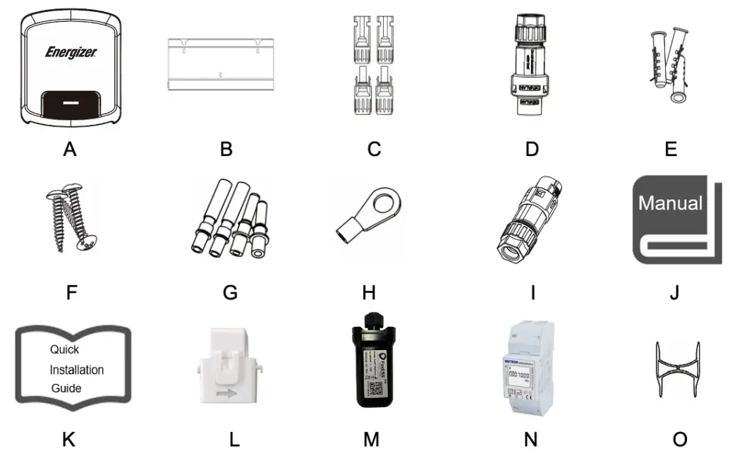
| Object | Quantity | Description | Object | Quantity | Description |
| A | 1 | Inverter | I | 1 | Communication connector |
| B | 1 | Bracket | J | 1 | Product manual |
| C | 4 | DC connector (F/M) | K | 1 | Quick installation guide |
| D | 1 | AC connector | L | 1 | CT (optional) |
| E | 3 | Expansion tube | M | 1 | WiFi/LAN/GPRS (optional) |
| F | 3 | Expansion screw | N | 1 | Meter (optional) |
| G | 4 | DC pin contact (2*positive, 2*negative) | O | 2 | Unlock tool |
| H | 1 | Earth terminal |
5.2 Preparation
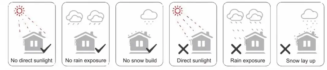
- Please refer to the Technical Data to make sure the environmental conditions fit the inverter’s requirements (degree of protection, temperature, humidity, altitude, etc.)
- Please avoid direct sunlight, rain exposure and snow build-up during installation and operation.
- To avoid overheating, always make sure the air flow around the inverter is not blocked.
- Do not install in places where gas or flammable substances may be present.
- Avoid electromagnetic interference that can compromise the correct operation of electronic equipment.
- The slope of the wall should be within ±5°.
5.3 Installation Space Required
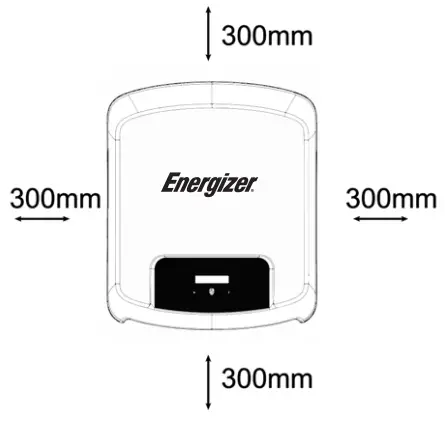
| Position | Min Size |
| Left | 300mm |
| Right | 300mm |
| Top | 300mm |
| Bottom | 300mm |
| Front | 300mm |
5.4 Tools Required
- Manual wrench
- Electric drill (drill bit set 8mm)
- Crimping pliers
- Stripping pliers
- Screwdriver

5.5 Installation Steps
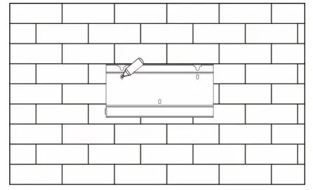
Step 1: Fix the bracket to the wall
- Choose the place you want to install the inverter. Place the bracket on the wall and mark the position of the 3 holes from bracket.
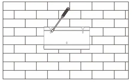
 • Drill holes with electric drill, make sure the holes are at least 50mm deep, and then tighten the expansion tubes.
- Insert the expansion tubes into the holes and tighten them. Install the bracket with the expansion screws.

 • Drill holes with electric drill, make sure the holes are at least 50mm deep, and then tighten the expansion tubes.
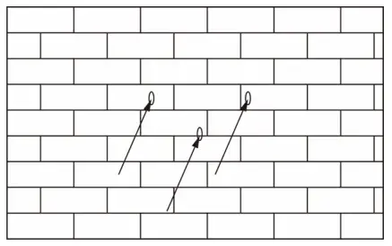
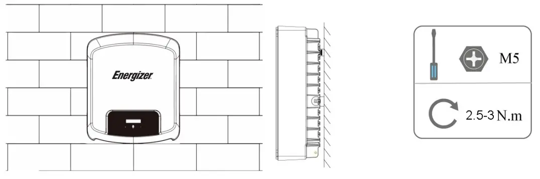
Step 2: Match the Inverter with wall bracket
- Hang the inverter over the bracket, slightly lower the inverter, and make sure the 2 mounting bars on the back are fixed with the 2 grooves from bracket properly.
5.6 Wiring Steps
Step 1: PV String Connection
This series inverters can be connected with 2-strings of PV modules. Please select suitable PV modules with high reliability and quality. Open circuit voltage of module array connected should be less than 600V, and operating voltage should be within the MPPT voltage range.2 grooves from bracket properly.
| Note! Please choose a suitable external DC switch if the inverter does not have a built-in DC switch. |
| Warning! PV module voltage is very high and within a dangerous voltage range, please comply with the electric safety rules when connecting. | |
| Warning! Please do not make PV positive or negative to ground! | |
| Note! PV modules — please ensure they are the same type, have the same output and specifications, are aligned identically, and are tilted to the same angle. In order to save cable and reduce DC loss, we recommend installing the inverter as near to the PV modules as possible. |
Note: PV connection mode below is not allowed.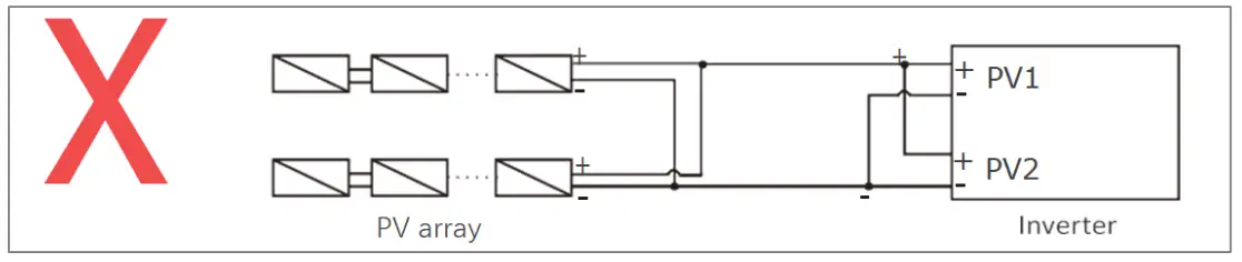 Step 2: DC Wiring
- Turn off the DC switch.
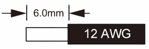
- Choose 12 AWG wire to connect the PV module.
- Trim 6mm of insulation from the wire end.

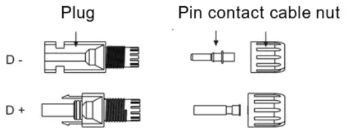
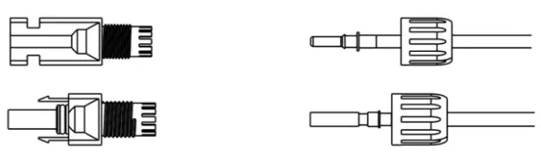
- Separate the DC connector as below.

- Insert striped cable into pin contact and ensure all conductor strands are captured in the pin contact.
- Crimp pin contact by using a crimping plier. Put the pin contact with striped cable into the corresponding crimping pliers and crimp the contact.

- Insert pin contact through the cable nut to assemble into back of the male or female plug. When you feel or hear a “click” the pin contact assembly is seated correctly.

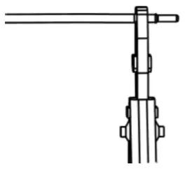
- Unlock the DC connector
- Use the specified wrench tool.
- When separating the DC + connector, push the tool down from the top.
- When separating the DC – connector, push the tool down from the bottom.
- Separate the connectors by hand.
- Grid Connection
This series inverters are designed for single-phase grid. Voltage range is 220/230/240V; frequency is 50/60Hz. Other technical requests should comply with the requirement of the local public grid.
| Model | Force 3S | Force 3.6S | Force 4.6S | Force 5S | Force 6S |
| Cable | 4mm² | 4mm² | 6mm² | 6mm² | 6mm² |
| Micro-Breaker | 25A | 25A | 40A | 40A | 40A |
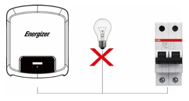
![]() WARNING! A micro-breaker for max output overcurrent protection device shall be installed between inverter and grid, and the current of the protection device is referred to the table above, any load SHOULD NOT be connected with the inverter directly.
WARNING! A micro-breaker for max output overcurrent protection device shall be installed between inverter and grid, and the current of the protection device is referred to the table above, any load SHOULD NOT be connected with the inverter directly.
Step 3: AC Wiring
- Check the grid voltage and compare with the permitted voltage range (refer to technical data).
- Disconnect the circuit-breaker from all the phases and secure against reconnection.
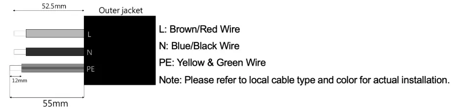
- Trim the wires:
- Trim all the wires to 52.5mm and the PE wire to 55mm.
- Use the crimping pliers to trim 12mm of insulation from all wire ends as below.

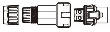
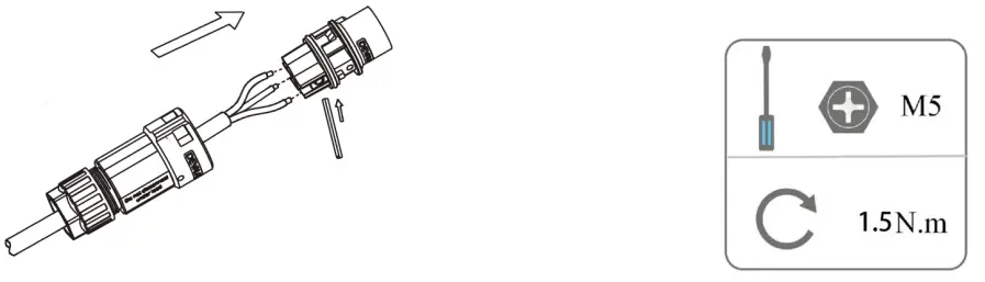
- Separate the AC plug into three parts as below.
- Hold middle part of the female insert, rotate the back shell to loosen it, and detach it from female inset.
- Remove the cable nut (with rubber insert) from the back shell.

- Slide the cable nut and then the back shell onto the cable.

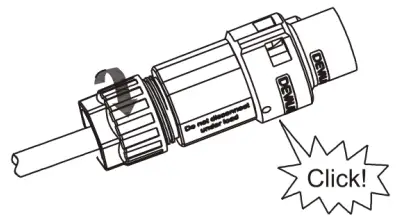
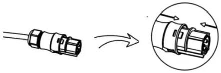
- Push the threaded sleeve into the socket, tighten up the cap on the terminal.

- Push the threaded sleeve to connection terminal until both are locked tightly on the inverter.

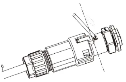
- Remove the AC connector, press the bayonet out of the slot with a small screwdriver or the unlock tool and pull it out, or unscrew the threaded sleeve, then pull it out

5.7 Earth Connection
Screw the ground screw with screwdriver as shown below: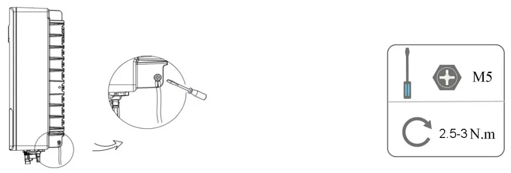
5.8 Communication Device Installation (Optional)
This series inverter is available with multiple communication options such as WiFi, LAN, GPRS, RS485, Meter and USB with an external device. Operating information like output voltage, current, frequency, fault information, etc., can be monitored locally or remotely via these interfaces.
• WiFi/LAN/GPRS (optional)
The inverter has an interface for WiFi/LAN/GPRS devices that allow this device to collect information from inverter; including inverter working status, performance etc., and update that information to monitoring platform (the WiFi/LAN/GPRS device is available to purchase from your local supplier).
Connection steps:
- For GPRS device: Please insert the SIM Card (please refer to the GPRS product manual for more details).
- For LAN device: Please complete the wiring between router and LAN device (please refer to the LAN product manual for more details).
- Plug the WiFi/LAN/GPRS device into “WiFi/GPRS” port at the bottom of the inverter.
- For WiFi device: Connect the WiFi with the local router, and complete the WiFi configuration (please refer to the WiFi product manual for more details).
- Set-up the site account on the monitoring platform (please refer to the monitoring user manual for more details).
• Hard Export limitation setting:
Short press the touch key to switch display or make the number+1. Long press the touch key to confirm your setting. There are three options in Set CT mode: Disable/CT/Meter, Please select according to the actual situation and then it will ask you to set the parameters(Long press for confirmation and switching to next digit, short press for changing the value).

Note: CT or Smart meter is required for hard export limitation function and the soft export limit function is controlled by platform. (Please refer to advanced configuration)
• CT (optional) (EM-EICT-120K-T210C or CTSA016)
This inverter has an integrated export management function. To enable this function, a power meter or CT must be installed. The CT should be clamped on the main live line of the grid side. The arrow on the CT should be pointing towards the grid. The white cable connects to CT+, and the black cable connects to CT-.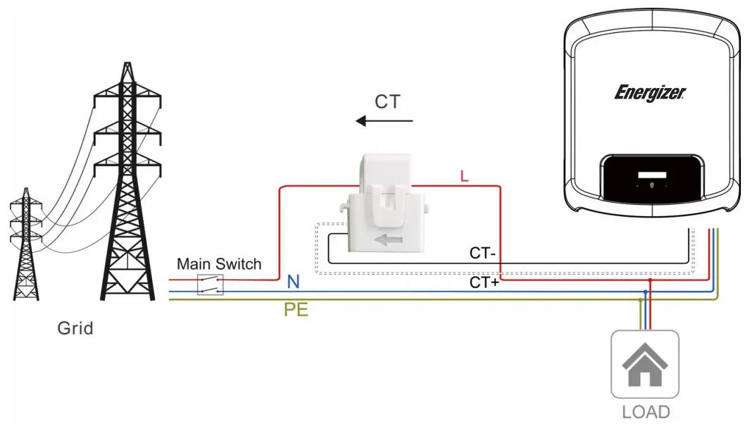
![]() Note! For a precise reading and control of power, a meter can be used instead of a CT. If the CT is fitted in the wrong orientation, anti-backflow function will fail.
Note! For a precise reading and control of power, a meter can be used instead of a CT. If the CT is fitted in the wrong orientation, anti-backflow function will fail.
• RS485/Meter
• RS485
RS485 is a standard communication interface which can transmit the real time data from inverter to PC or other monitoring devices.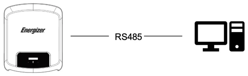
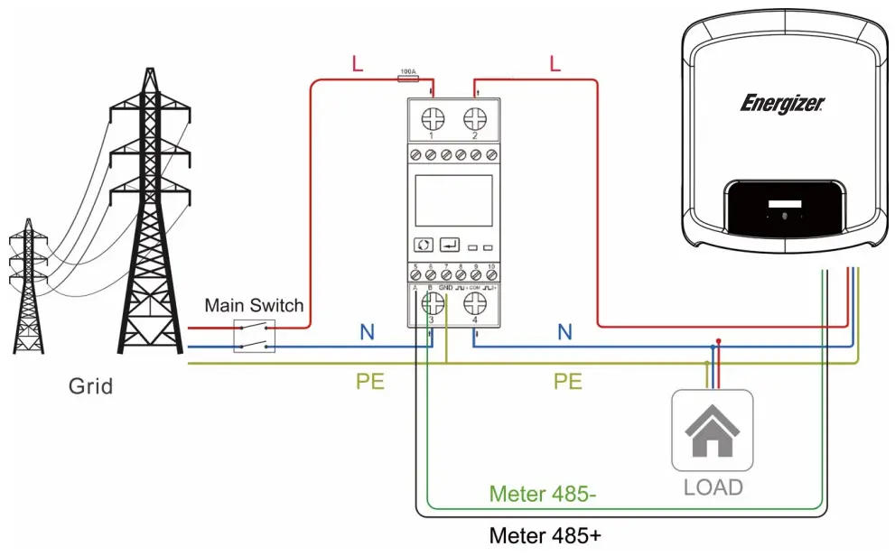
• Meter (optional) (Eastron-SDM230-Modbus)
The inverter has integrated export limitation functionality. To use this function, a power meter or a CT must be installed. For Meter installation, please install it on the grid side.
• DRM0/ESTOP
| Model | Socket asserted by shorting pins | Function | |
| DRM0 | 5 | 6 | Operate the disconnection device. |
| ESTOP | 5 | 8 | Emergency stop the inverter. |
DRM0 setting
Short press the touch key to switch display or make the value+1. Long press the touch key to confirm your setting. The PIN definitions of CT/RS485/DRM0/ESTOP interface are as below.
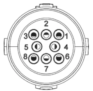
| PIN | 1 | 2 | 3 | 4 | 5 | 6 | 7 | 8 |
| Definition | CT+ | CT- | METER 485- | METER 485+ | GND | DRM0 | NC | ESTOP |
• Upgrade
The inverter firmware can be updated locally through a U-disk. Please refer to following steps.
a) Please contact our service support team to get the latest firmware, and copy the files to U-disk using the following file path:
Master: “Update\master\xxxxx_Master_Vx.xx.hex”
Slave: “Update\slave\xxxxx_Slave_Vx.xx.hex”
Manager: “Update\manager\xxxxx_manager_Vx.xx.hex”
Note: Vx.xx is version number.
![]() Warning! Make sure the directory structure is strictly in accordance with the above. Do not modify the program file name! It may cause the inverter to cease functioning.
Warning! Make sure the directory structure is strictly in accordance with the above. Do not modify the program file name! It may cause the inverter to cease functioning.
b) Make sure the DC switch (if no DC switch, please disconnect the PV connector) is off and the AC is disconnected from the grid.
Unscrew the waterproof lid of the USB port using a flat-headed screwdriver as below.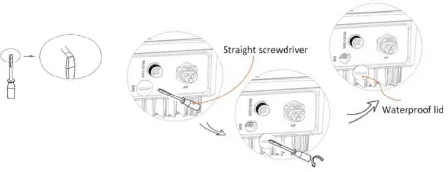
c) Wait until the LCD is off, then insert the U-disk and turn on the DC switch or re-connect the PV connector, the LCD will show picture as below.
d) Short press on the button to select the type of firmware you want to upgrade, then long press on the button, the inverter will start the upgrade process automatically.
Note: Make sure you have put the correct file on the U-disk, if you only want to upgrade one chip, simply add the one relevant file onto the U-disk, if you want to upgrade all chips, you need add all files.
e) After the upgrade is complete, please turn off the DC switch or disconnect the PV connector again, then remove the U-disk and insert the waterproof cover.
![]() Warning! Make sure the input voltage is more than 120V (preferably in good illumination conditions), and do not remove the U-disk during update, otherwise the update may fail. If there is any problem or error during the upgrade, please contact our service team for help.
Warning! Make sure the input voltage is more than 120V (preferably in good illumination conditions), and do not remove the U-disk during update, otherwise the update may fail. If there is any problem or error during the upgrade, please contact our service team for help.
f) Turn on the DC switch or connect the PV connector to power on the inverter to finish the upgrade process.
• Isolation Fault (Australia Market Only)
This inverter complies with IEC 62109-2 clause 13.9 for earth fault alarm monitoring. If an Earth Fault Alarm occurs, the fault code Isolation fault will be displayed on the inverter screen and the RED LED indicator will light up. The inverter should be installed in a high traffic area so the alarm will be noticed.
• Reactive Power Regulation for Voltage Variation (Volt-VAr Mode)
Details of how to enable this mode are contained in the “Advanced Configuration Guide’, which can be accessed at our website at https://www.energizersolar.com
• Power Derating for Voltage Variation (Volt- Watt Mode)
Details of how to enable this mode are contained in the “Advanced Configuration Guide”, which can be accessed at our website at https://www.energizersolar.com
5.9 Inverter Start-Up
Please refer to the following steps to start-up the inverter:
a) Check if device is fixed well on the wall;
b) Make sure all DC breakers and AC breakers are disconnected;
c) Ensure AC cable is connected to the grid correctly;
d) All PV panels are connected to inverter correctly; DC connectors that are not used should be sealed by cover;
e) Turn on the external AC and DC connectors;
f) Turn the DC switch to the “ON” position (if equipped with DC switch on the inverter).
If the LED is not green, please check the below:
– All the connections are correct.
– All the external disconnect switches are closed.
– The DC switch of the inverter is in the “ON” position.
Note:
– When starting the inverter for the first time, the country code will be set by default to the local settings. Please check if the country code is correct.
– Set the time on the inverter using the button or by using the APP.
Below are the three possible inverter states indicating that the inverter has started up successfully.
Waiting: Inverter is waiting to check the DC input voltage from panels is greater than 80V (lowest start-up voltage) but less than 120V (lowest operating voltage), display will indicate the Waiting status and green LED will flash.
Checking: Inverter will check DC input environment automatically when DC input voltage from the PV panels exceeds 120V and PV panels have enough energy to start inverter, display will indicate the Checking status and green LED will flash.
Normal: Inverter begins to operate normally with green light on. Meanwhile feedback energy to grid, LCD displays present output power.
Note: You can go to the setting interface on the display to follow the instructions if it is the first time to start up.
• Complete inverter Start-up guide
After the initial start-up the inverter, display will go to the language settings page, short press to switch language and long press to confirm selection. Once language set, display will guide to set the safety regulation. Short press to switch safety regulation (Please select the Region A/B/C, please confirm with local grid company on which Region to select), and long press to confirm selection. When Region is selected, the inverter loads all the Region values for power quality response modes and grid protection settings. After the initial commission, the setting will be locked and the Country code and Power Quality Response Mode will be viewed only.
Note: *Australia only
| Region A | Region B | Region C | NZ | |||
| VOLT-WATT | Voltage | Vw1 | 253V | 250V | 253V | 242V |
| Vw2 | 260V | 260V | 260V | 250V | ||
| (P)% OF Stated | Vw1 | 100% | 100% | 100% | 100% | |
| Vw2 | 20% | 20% | 20% | 20% | ||
| VOLT-VAR | Voltage | Vv1 | 207V | 205V | 215V | 207V |
| Vv2 | 220V | 220V | 230V | 220V | ||
| Vv3 | 240V | 235V | 240V | 235V | ||
| Vv4 | 258V | 255V | 255V | 244V | ||
| (P)% OF Srated | Vv1 | 44% Supplying | 30% Supplying | 4496 Supplying | 60% Supplying | |
| Vv2 | 0% | 0% | 0% | 0% | ||
| Vv3 | 0% | 0% | 0% | 0% | ||
| Vv4 | 60% Absorbing | 40% Absorbing | 60% Absorbing | 60% Absorbing | ||
| Fixed PF | Fixed PF | Default | 1 | 1 | 1 | 1 |
| Range | -0.8-0.8 | -0.8-0.8 | -0.8-0.8 | -0.8-0.8 | ||
| Reactive power | Reactive power | Default | 0 | 0 | 0 | 0 |
| Range | -60%-60% | -60%-60% | -6096-60% | -6096-60% | ||
| Power Rate Limit | Wgra+ | Default | 16% | 16% | 16% | 16% |
| Range | 596-100% | 596-100% | 596-100% | 5%-10096 | ||
| Wgra- | Default | 16% | 16% | 16% | 16% | |
| Range | 596-100% | 596-100% | 596-100% | 596-100% | ||
| Protection Setting | 10 Mins Voltage | V | 258V | 258V | 258V | 249V |
| Freq Derate set | OVF | START | 50.25Hz | 50.15Hz | 50.5Hz | 50.2Hz |
| STOP | 52HZ | 52Hz | 53Hz | 52Hz | ||
| UNF | START | 49.75Hz | 49.85Hz | 49.5Hz | 49.8Hz | |
| STOP | 48Hz | 48Hz | 47Hz | 48Hz |
- Enable/Setup Power Quality Response Modes
Please refer to the Advanced Configuration Guide. - Setup Region code (After initial commission)
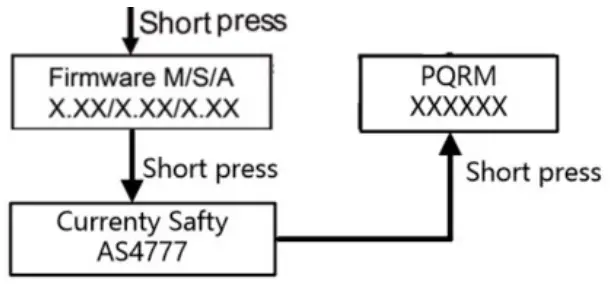
Please short press button 12 times until the inverter screen show Setting, then long press button and enter the password* , then press the button one time until it show Safety, then long press the button to enter the option list. - Check Firmware version, Region code and Power Quality Response Modes.
Please refer to the section 6.2.
Firm ware version: Please short press the button 8 times.
Region Code: Please short press the button 9 times.
Power Quality Response Modes: Please short press the button 10 times.
Note! Please set-up the inverter if it is the first time to start-up. The above steps are for the regular start-up of the inverter. If it is the first time to start up the inverter, you need to carry-out the initial set-up of the inverter.![]() Warning! Power to the unit must be turned on only after installation work has been completed. All electrical connections must be carried out by qualified personnel in accordance with legislation in force in the country of installation.
Warning! Power to the unit must be turned on only after installation work has been completed. All electrical connections must be carried out by qualified personnel in accordance with legislation in force in the country of installation.
5.10 Auto-test
Auto test procedures:
- Connect the inverter communication interface (COM) to computer via USB-RS485 converter.
- Closed DC side circuit breaker and AC side circuit breaker.
- Open the program Auto Test Tool.
- Select the COM port and Baud rate, Click “Open” button to connect COM port.
- Click “Start” button to start self test.
5.11 Inverter Switch Off
Please follow the below steps to switch off the inverter:
a) Switch off the inverter AC isolation switch.
b) Switch off the DC isolation switch and allow 5 minutes for the inverter to power down completely.
Operating
6.1 Control Panel
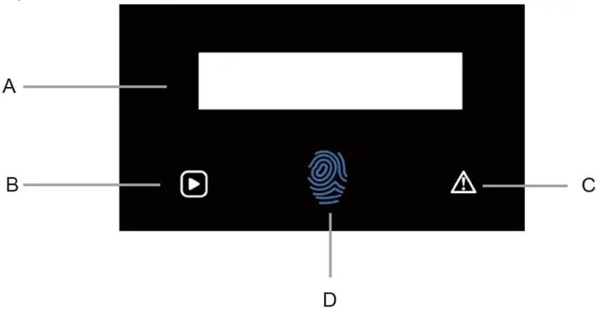
| Object | Name | Function |
| A | LCD Screen | Display the information of the inverter. |
| B | Indicator LED | Green: The inverter is in normal state. |
| C | Red: The inverter is in fault mode. | |
| D | Touch Key | The touch key is used to set the LCD to display different parameters. Press time <1s (short press): Next; Press time >2s (long press): Enter. Wait time 15s: Return to start. |
6.2 Function Tree
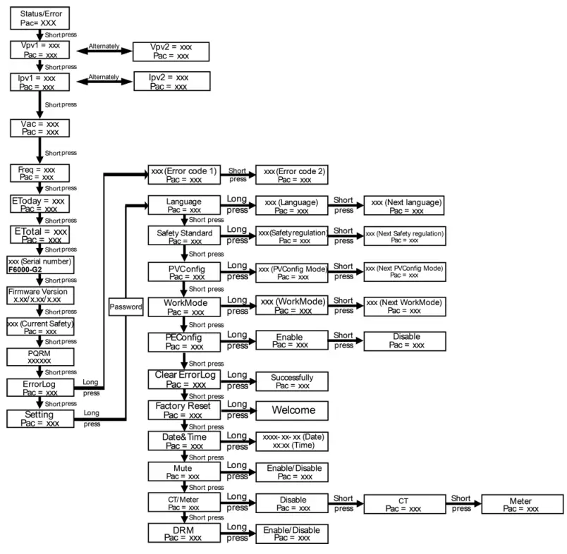
Note:
- Short press to select, long press to confirm.
- The default password will be provided to an installer upon request. Only a qualified installer or distributor are permitted to modify the settings, end users are not able to modify to do the settings.
The following details and other details, are available by following the function tree above. You may be prompted to enter the password, the password is available upon request. - Firmware Version
- Region setting (and setpoints) for grid protection settings
- Region setting (and setpoints) for power quality response modes
Maintenance
This section contains information and procedures for solving possible problems with the inverters and provides you with troubleshooting tips to identify and solve most problems that can occur.
7.1 Alarm List
| Fault Code | Solution |
| SPS Fault | – Turn off the PV and grid, reconnect them. – Please seek for help from us if it does not go back to normal state. |
| Bus OVP | – Disconnect PV (+), PV (-) with DC. – After the LCD switches off, reconnect and check again. – Please seek for help from us if it does not go back to normal state. |
| DCI Fault | – Wait for one minute after the inverter reconnects to grid. – Disconnect PV (+), PV (-) with DC. – After the LCD switches off, reconnect and check again. – Please seek for help from us if it does not go back to normal state. |
| EEPROM Fault | – Disconnect PV (+), PV (-) with DC. – After the LCD switches off, reconnect and check again. – Please seek for help from us if it does not go back to normal state. |
| GFC Fault | – Disconnect DC and AC connector, check the surrounding equipment on the AC side. – Reconnect the input connector and check the state of inverter after troubleshooting. – Please seek for help from us if it does not go back to normal state. |
| GFCD Fault | – Disconnect PV (+), PV (-) with DC. – After the LCD switches off, reconnect and check again. – Please seek for help from us if it does not go back to normal state. |
| Grid 10Min OVP | – System will reconnect if the grid is back to normal. – Or seek for help from us if it does not go back to normal state. |
| Grid Freq Fault | – Wait for one minute, grid may go back to normal working state. – Make sure that grid voltage and frequency complies with standards. – Or please seek for help from us. |
| Grid Lost Fault | – Please check grid-connection, e.g., wires, interface etc. – Checking grid usability. – Or seek for help from us. |
| Intransigent Fault | – Disconnect PV (+), PV (-) with DC. – After the LCD switches off, reconnect and check again. – Please seek for help from us if it does not go back to normal state. |
| Grid Voltage Fault | – Wait for one minute, grid may go back to normal working state. – Make sure that grid voltage and frequency complies with standards. – Or, please seek for help from us. |
| Consistent Fault | – Disconnect PV (+), PV (-) with DC. – After the LCD switches off, reconnect and check again. – Please seek for help from us if it cannot go back to normal state. |
| Isolation Fault | – Check the impedance among PV (+), PV (-) and ground. Impedance should be >1Mohm. – Please seek for help from us if it cannot be detected or the impedance is <1Mohm. |
| Ground Fault | – Check the voltage of neutral and PE. – Check AC wiring. – Restart inverter, if error message persists, seek for help from us. |
| Fault Code | Solution |
| OCP | – Turn off the PV and grid, reconnect them. – Or seek for help from us if it does not go back to normal. |
| PLL Fault | – System will reconnect if the utility is back to normal. – Or seek for help from us if it does not go back to normal state. |
| PV OVP | – Check the panel’s open-circuit voltage whether the value is similar or already >550Vdc. – Please seek help from us when voltage ≤550Vdc. |
| Relay Fail | – Disconnect PV (+), PV (-) with DC. – After the LCD switches off, reconnect and check again. – Please seek for help from us if it does not go back to normal state. |
| Sample Fault | – Disconnect PV (+), PV (-) with DC. – After the LCD switches off, reconnect and check again. – Please seek for help from us if it cannot go back to normal state. |
| Comm Lost | – Disconnect PV+, PV-, reconnect them – Or seek for help from us if it does not go back to normal state. |
| MS Comm Lost | – Disconnect PV (+), PV (-) with DC. – After the LCD switches off, reconnect and check again. – Please seek for help from us if it cannot go back to normal state. |
| Over Temp | – Check if the environment temperature is over the limit. – Or seek for help from us. |
7.2 Troubleshooting
a) Please check the fault message on the System Control Panel or the fault code on the inverter information panel. If a message is displayed, record it before doing anything further.
b) Attempt the solution indicated in table above.
c) If your inverter information panel is not displaying a fault light, check the following to make sure that the current state of the installation allows for proper operation of the unit:
(1) Is the inverter located in a clean, dry, adequately ventilated place?
(2) Have the DC input breakers opened?
(3) Are the cables adequately sized?
(4) Are the input and output connections and wiring in good condition?
(5) Are the configurations settings correct for your particular installation?
(6) Are the display panel and the communications cable properly connected and undamaged?
Contact Customer Service for further assistance. Please be prepared to describe details of your system installation and provide the model and serial number of the unit.
7.3 Routine Maintenance
• Safety check
A safety check should be performed at least every 12 months by a qualified technician who has adequate training, knowledge and practical experience to perform these tests. The data should be recorded in an equipment log. If the device is not functioning properly or fails any of the tests, the device has to be repaired. For safety check details, refer to section 2 of this manual.
• Maintenance checking list
During the process of using the inverter, the responsible person shall examine and maintain the machine regularly. The required actions are as follows.
– Check that if the cooling fins at the rear of the inverters are collecting dust/dirt, and the machine should be cleaned when necessary.
This work should be conducted periodically.
– Check that if the indicators of the inverter are in normal state, check if the display of the inverter is normal. These checks should be performed at least every 6 months.
– Check if the input and output wires are damaged or aged. This check should be performed at least every 6 months.
– Get the inverter panels cleaned and their security checked at least every 6 months.
Note: Only qualified individuals may perform the following works.
Decommissioning
8.1 Dismantling the Inverter
- Disconnect the inverter from DC Input and AC output. Wait for 5 minutes for the inverter to fully de-energize.
- Disconnect communication and optional connection wirings. Remove the inverter from the bracket.
- Remove the bracket if necessary.
8.2 Packaging
If possible, please pack the inverter with the original packaging. If it is no longer available, you can also use an equivalent box that meets the following requirements.
- Suitable for loads more than 30 kg.
- Contains a handle.
- Can be fully closed.
8.3 Storage and Transportation
Store the inverter in dry place where ambient temperatures are always between -40°C – +70°C;
Take care of the inverter during the storage and transportation; keep less than 4 cartons in one stack.
When the inverter or other related components need to be disposed of, please ensure it is carried out according to local waste handling regulations. Please be sure to deliver any inverter that needs to be disposed from sites that are appropriate for the disposal in accordance with local regulations.
Remote Monitoring & Application
9.1 Setting up remote monitoring
To connect to the Energizer Solar application and remote monitor your Solar System via your mobile device. Please follow the instructions within the Energizer Solar App User Guide. A mobile device or laptop, and a Smart Wi-Fi dongle is required for installation and setup. To download the Energizer Solar application, please scan the QR Codes below based on your device requirements.
 |  |  |
| https://apps.apple.com/au/app/energizer-solar/id1611705037 | https://play.google.com/store/apps/details?id=com.fox.energizer |
| Australia Level 35, 477 Collins St, Melbourne Victoria 3000, Australia +61 1300 757 827 | Europe The Black Church, St Mary’s Place Dublin D07 P4AX, Ireland +353 1 254 8222 | North America 888 Prospect Street La Jolla California 92037 (424) 254-5344 |
![]() [email protected]
[email protected]![]() energizersolar.com
energizersolar.com
© 2022 Energizer. Energizer and certain graphic designs are trademarks of Energizer Brands, LLC and related subsidiaries and are used under license by 8 Star Energy Pty Ltd.
All other brand names are trademarks of their respective owners. Neither 8 Star Energy Pty Ltd nor Energizer Brands is affiliated with the respective owners of their trademarks. ![]()


