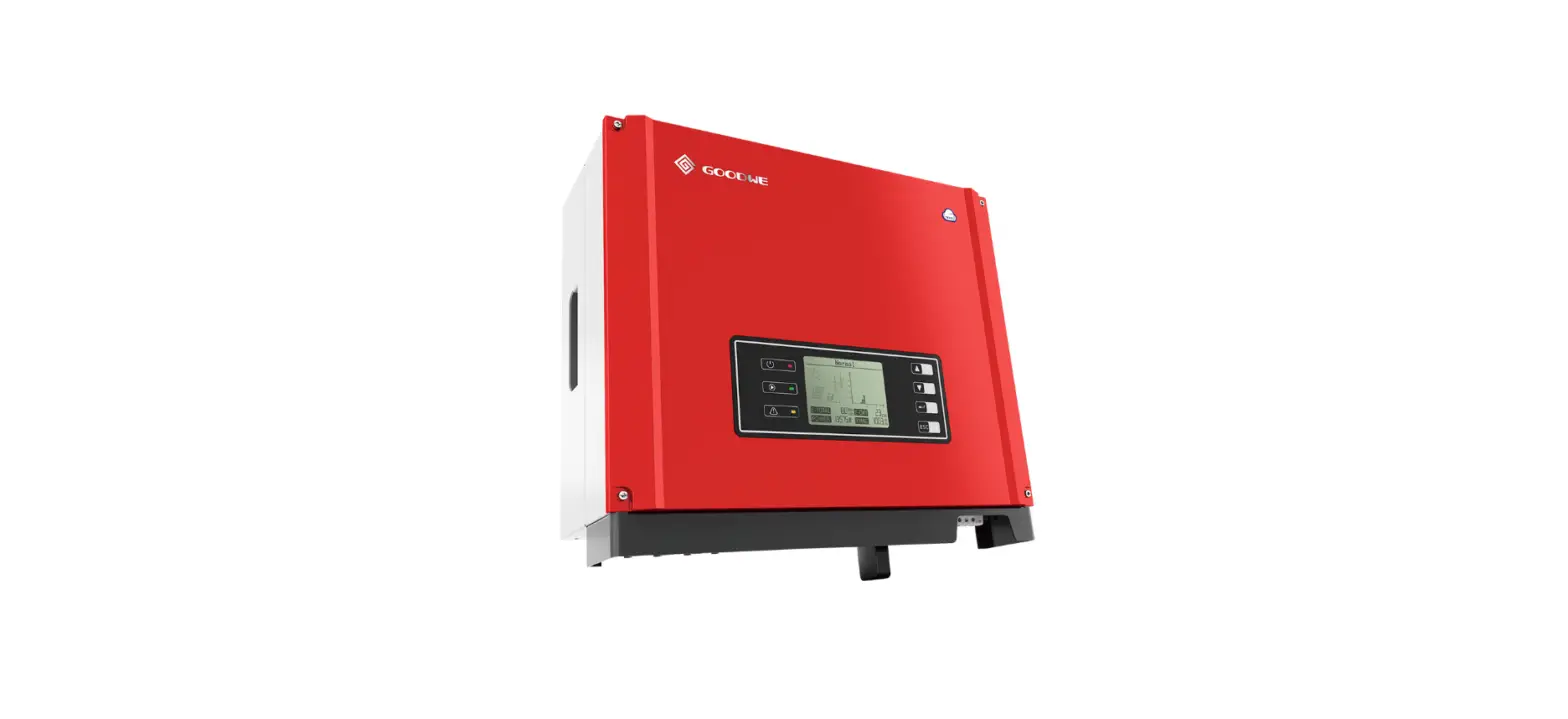
GOODWE XS Series Single Phase 2 MPPT Small Residential Solar Inverter
INSTRUCTION
Safety Measures & Warning
- The XS-Series strictly conforms and has been tested according to international safety regulations. GOODWE strongly advises installers to follow the local safety regulations during the commissioning, operation and maintenance of the XS-Series inverter. An improper operation may result in electric shocks or damage to equipment and property.
- The installation, maintenance and connection of the inverters must be performed by qualified personnel, in compliance with local electrical standards, regulations and following the regulations of the local power suppliers, companies and related authorities.
- To avoid electric shocks, the DC input and AC output port of the inverters must be disconnected and wait at least 5 minutes before performing any installation or maintenance.
- The temperature of some components of the inverters may exceed 60℃ during operation. To avoid being burnt, do not touch the inverter during operation. Let it cool before touching it.
- Keep children away from the inverter.
- Touching or changing inverter components without following the GOODWE’s manual instructions may cause personal injury, damage the inverters and ultimately be a reason for warranty invalidation.
- The electronic components of the inverter may be damaged by static electricity. Appropriate methods must be adopted to prevent such damage, otherwise the GOODWE’s warranty may be void.
- Make sure that the output voltage of the proposed PV array is lower than the maximum rated input voltage of the inverter; otherwise the inverter may be damaged and the warranty may be void.
- When exposed to sunlight, the PV array generate dangerous high DC voltage; we strongly operators to strictly follow the GOODWE’s instructions and avoid actions that put lives at risk.
- The PV modules should have as a minimum an IEC61730 class A rating protection.
- If the equipment is used in a way not authorized by the GOODWE, the equipment built-in protections may be damaged.
- In order to achieve a complete isolation of the equipment: Turn off the DC switch, disconnect the DC terminal, the AC terminal and the AC breaker
- Do not insert or pull the AC or DC terminals when the inverter is in operation.
- An earthing photovoltaic system requires the installation of an Arc Fault Detector on the DC side.
- The below bullet points are not understandable. Urgently review!
- The inverter can exclude the possibility of DC residual currents to 6mA in the system,
- Where an external RCD is required in addition to the built-in RCMU, type A RCD must be used to avoid tripping.
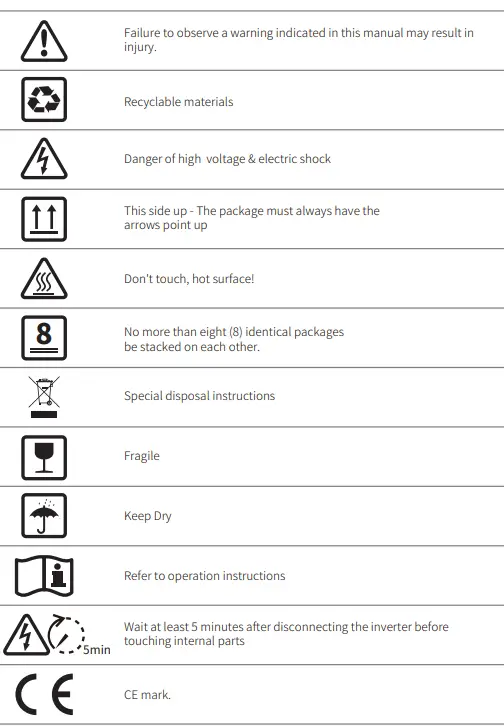
Symbols
Product Introduction
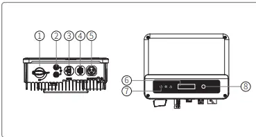
| Item | Name | Description |
| 1 2 | DC Switch (Optional) PV Input Terminal | During normal operation it is in “on” state, it can shut down the inverter after it is disconnected from the grid by the AC breaker. |
| For PV string connection | ||
| 3 | WiFi/LAN Module Port (Optional) | For WiFi/LAN communication |
| 4 5 | CT & DRED/Remote Shutdown/RS485 Communication Port AC Output Terminal | For CT and DRED & Remote Shutdown & RS485 Communication |
| 6 | LCD | For AC cable connection |
| 7 | Indicator Light | Inverter operation data viewing and parameter configuration. |
| 8 | Button | Display the state of the inverter |
| For configuration and viewing parameters. |
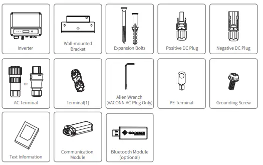
Package
The unit is thoroughly tested and strictly inspected before delivery. Damage may still occur during shipping.
- Check the package for any visible damage upon receiving.
- Check the inner contents for damage after unpacking.
- Check the package list below.

Installation
Mounting Instructions
- In order to achieve optimal performance, the ambient temperature should be lower than 45℃.
- For easy maintenance, we suggest to install the inverter at eye level.
- Inverters should not be installed near flammable and explosive items. Strong electro-magnetic charges should be kept away from installation site.
- Product label and warning symbols should be placed at a location that is easy to read by the users.
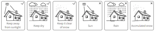
- Make sure to install the inverter at a place where it is protected from direct sunlight, rain and snow.

Equipment Installation
Select installation location
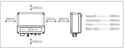
- Please take the following points into consideration when you are selecting a proper location to install inverter.
- Please choose appropriate mounting methods and installation location in terms of weight and dimension of inverter.
- The location must be well ventilated and sheltered from direct sunlight.
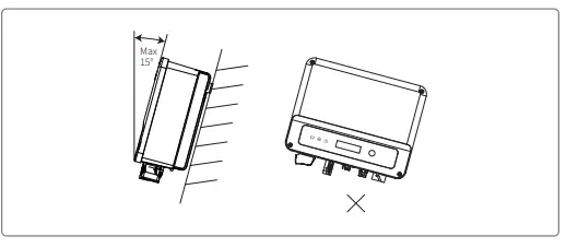
- Install inverter vertically or with a backward tilt within 15 degrees. No lateral tilt is allowed.


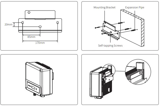
Mounting procedure
- Use the wall-mount bracket as a template and drill holes with 10mm in diameter and 80 mm in depth on the wall.
- Fix the wall-mount bracket on the wall with the expansion bolts in the accessories bag.
- Hold the inverter by the side groove.
- Mount the inverter onto the wall-mount bracket

Electrical Connection
Connection To The Grid (AC Side Connection)
- When connecting the inverter make sure to adjust the voltage and the frequency in compliance with the grid regulations and the specifications of the GOODWE.
- Add a breaker or fuse to the AC side. Please note that the specification should be more than 1.25 times of rated AC output current.
- The PE line of the inverter should be connected to earth. Make sure the impedance of neutral wire and earth wire is less than 10ohm.
- Disconnect the breaker or fuse between the inverter and the utility.
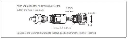
 Please note that there are two AC connector brands compatible with the inverters: VACONN and Exceedconn. Choose one of the to connect the inverter to the grid.
- When laying the AC line make sure that the protective earthing conductor is not strained. Inverters are compatible with two brands of AC connector: VACONN and Exceedconn

 Please note that there are two AC connector brands compatible with the inverters: VACONN and Exceedconn. Choose one of the to connect the inverter to the grid.
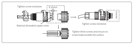
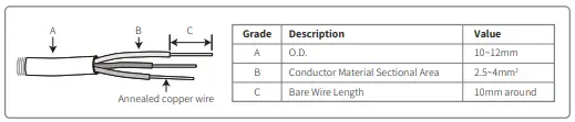
AC CABLE SPECIFICATION
AC circuit breaker and leakage current protection device
Please install an independent two pole circuit breaker to protect the inverter and make sure it is safe to disconnect it from the grid. In addition to the built-in RCMU, an external RCD is required to ensure that the inverter system does not carry DC residual currents. To avoid tripping, the types A can be used.
| Inverter Model | Recommended Circuit Breaker Specifications |
| GW700-XS/GW1000-XS/GW1500-XS | 16A |
| GW2000-XS/GW2500-XS/GW3000-XS GW2500N-XS/GW3000N-XS /GW3300-XS/GW3KB-XS | 25A |
DC Side Connection
- Before connecting the PV strings, please ensure the plug connectors have the correct polarity.
- Incorrect polarity has the potential to cause permanent damage to the unit.
- The open circuit voltage of the PV strings cannot exceed the maximum input voltage of the inverter.
- Only the GOODWE supplied DC connectors are suitable for use.
- The positive and negative pole should not be connected to the PE wire (ground wire). Not following this instruction may cause damage to the inverter.
- Do not connect the positive or negative poles of the PV string to the PE wire. Not following this instruction may cause damage to the inverter.
- Red represents positive, black represents negative
There are four types of DC connectors, DEVALAN, MC4, AMPHENDL H4 and QC4.10 series.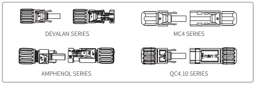
DC cable specification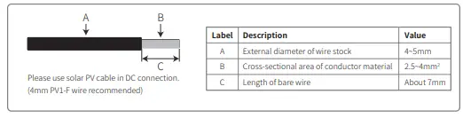
The installation method of DC connector.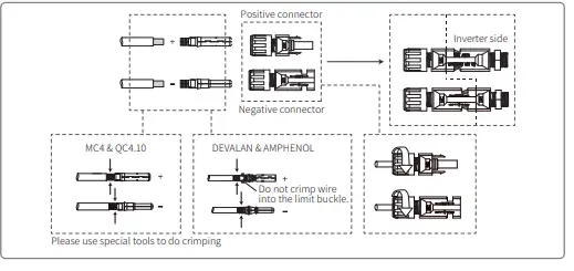
Earth Terminal Connection
The inverter is equipped with earth terminal according to the requirement of EN 50178. All non-current carrying exposed metal parts of the equipment and other enclosures in the PV power system must be grounded. Please follow the steps below to connect “PE” cable to ground.
Communication Connection
Wi-Fi Communication
Wi-Fi communication option is only applicable to Wi-Fi version inverter and Wi-Fi communication module is required. Please refer to “Wi-Fi Configuration Instruction” in the accessory box for detailed instruction. The WiFi module installation of XS series are shown as below
LAN Communication
LAN Communication is only application to LAN version inverter and LAN Communication module is required.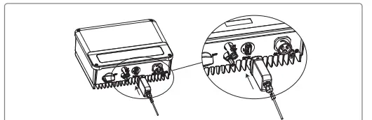
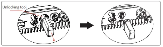
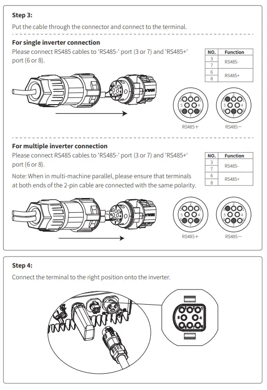
RS485 Communication
RS 485 communication option is only applicable to RS485 version inverter and RS485 communication function is required. RS485 communication connection of XS series are shown as below.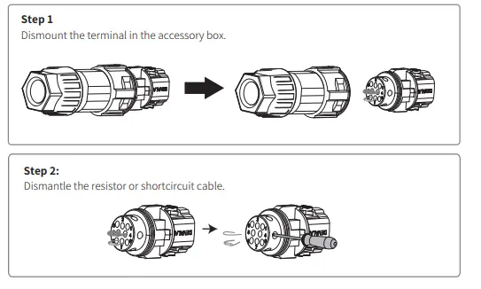
Export Power Limit Connection Diagram
The methods of connecting the Power Limiting device CT is shown below. CT90-5 or CT90-30 is recommended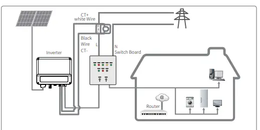
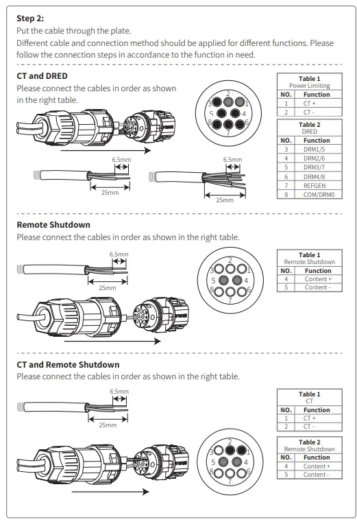
DRED / Remote Shutdown / CT(Power Limit Device) Connection
DRED (Demand response enabling device) is only for Australian and New Zealand installations, in compliance with Australian and New Zealand safety requirements. Contat the after-sales service to get the DRED terminal if you need to use DRED function. DRED function is off by default. Start this function via SolarGo App if it’s needed. Remote shutdown is only for Europe installations, in compliance with European safety requirements. And Remote shutdown device is not provided by GOODWE. Detailed operation is shown as below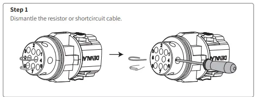
Earth Fault Alarm
In compliance with the section 13.9 of IEC62109-2, the XS series inverter is equipped with an earth fault alarm. When earth fault occurs, the fault indicator at the front LED screen will light up. On inverters with Wi-Fi communication, the system sends an email with the fault notification to the customer. For inverters without Wi-Fi, the buzzer of the inverter will keep ringing for one minute and ring again after half an hour until the fault is resolved. (This function is only available in Australia and New Zealand).
SEMS Portal
SEMS Portal is an online monitoring system. After completing the installation of communication connection, you can access www.semsportal.com or download the App by scanning the QR code to monitor your PV plant and device. Please contact the after-sales for more operation of SEMS Protal.
System Operation
LCD PANEL

Indicator lights in Yellow/Green/Red correspondently refer to: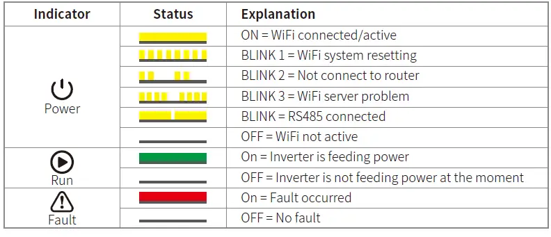
Operation Method
There are 2 modes of button operation: Short press the button and long press the button. In all levels of menu, if no action is taken, the backlight of the LCD will switch off, the LCD will automatically revert to the first item of the first level menu, and any modifications made to the data will be stored into internal memory.
Set Safety Country
After powering on for the first time, the inverter prompts Select Country/Region, please short press until “GW1000-XS Pac=****.0W” is displayed, and then set the safety region. The inverter cannot be connected to the grid before the safety-related area is set. If display shows “GW1000-XS Pac=****.0W”, then long press the button to enter the second level menu. Short press to browse the countries available. Please wait after choosing the suitable country’s safety setting, the display will show “setting…” and skip to “Set OK” or “Set Fail”.
LCD
A schematic of the display screen is shown as below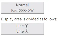
Display Area
- Line 1 — Working status information
- Line 2—Diaplays of the real-time power generated by the inverter.
- This area displays the status information. “Waiting” indicates the inverter is standing by for power generation; “Checking **S” (checking time is based on safety, and varies from country to country) indicates is self-checking, counting down and preparing for power generation. “Normal” indicates the inverter is generating power. If any condition of the system is abnormal, the screen will display an error message.
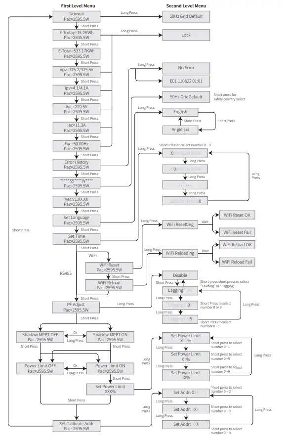
- Through button operation, the screen can display different information such as operation parameters and power generation status is in this area. There are two levels of menus, and the flow chart of first level menu is shown below:
Use Of The LCD
The display allows accessing the configuration of the basic parameters. All the language, time and country settings can be configured by buttons. The menu, shown in the LCD displays area has two levels of menu. Short or long press the button will take you between menus and through each menu. Items in the first level menu that have no second level are locked. For these items, when the button is pressed for two seconds, the LCD will display the word “Lock” followed by data relating to the first level menu item. The locked menu can only be unlocked under system mode switching, fault occurrence or button operation.
- When the PV panel is feeding power to the inverter, the LCD displays the first-level menu.
- The initial display is the first item to the first level menu, and the interface displays the current status of the system.
- It shows “Waiting” in the initial state; its display “Normal” during powe generation mode; if there is something wrong with the system, an error message is displayed.
Please refer to “5.3 Error message”.
- View PV voltage, PV current, grid voltage, current and frequency:
- Short press the button to enter the “E-Today” menu which displays the total power generation for today.
- Short press the button to enter the “E-Today” menu which displays the total power generation until today.
- Short press the button to enter the “Vpv” menu which displays the PV voltage in “V”.
Basic Setting
Set language
Short press the button to enter the “Set Language” menu. Long press the button to enter the second level menu. Short press the button to browse the languages available.
Set time
From the first level “Set Language” menu, short press the button to enter the “Set Time” menu. Long press the button to enter the second level menu. The initial display is “2000-00-00 00:00”, in which the first four numbers represent the year (e.g. 2000~2099); the fifth and sixth numbers represent the month (e.g. 01~12); the seventh and the eighth numbers represent the date (e.g. 01~31). The remaining numbers represent the time. Short press the button to increase the number in current location, and press to move the cursor to next position.
Set protocol:
The function is only used for service personnel, setting a wrong protocol could lead to communication failure. From the first level “Set Time” menu, short press the button to enter
Power Limiting Function Setting
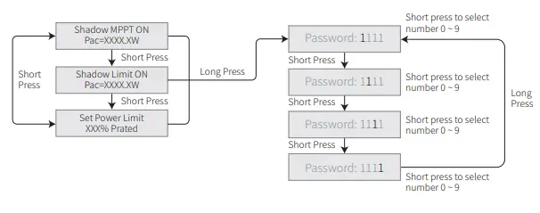
Enter Password:
Please enter the password (valid for 10 minutes) before changing the power limiting state (the default is OFF) and the power limiting setting (the default is 2% rated power): Long press the button to enter password input menu. The initial display “1111” is the default password. Short press the button to increase the number in current location and long press to move to the cursor to next position. The operations are shown as below
Modify Password
Long press the button to enter password change menu. Short press to increase the number in current location, long press to move the cursor to next position. If the old password is right, the new password will be stored after 20 seconds without any input.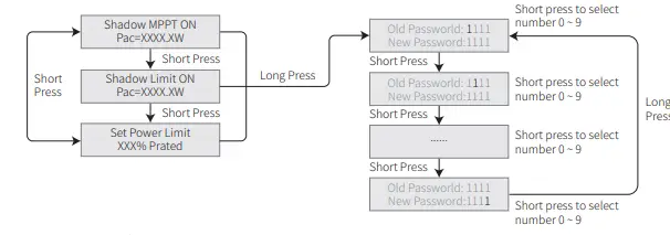
The operation are shown as below.
Auto-Test
The default setting of this function is disabled which can only be available in Italy safety. Short press the button until LCD displays “Auto Test”, and long press the button to start this function. if auto test is finished, short press the button until LCD displays “Auto Test Result”, and long press the button to check the result.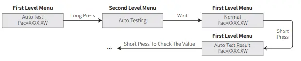
Error Message
An error message will be displayed on the LCD is a fault occurs.
| Error code | Error message | Description |
| 03 | Fac Fail | Grid frequency out of permissible range |
| 14 | Isolation Fail | Ground insulation impedance is too low |
| 15 | Vac Failure | Grid voltage out of permissible range |
| 17 | PV Over Voltage | Overvoltage at DC input |
| 19 | Over Temperature | Over Temperature on the case |
| 23 | Utility Loss | Utility is unavailable |
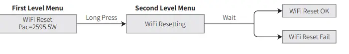
Wi-Fi Reset & Wi-Fi Reload
- These functions are only available for Wi-Fi model inverters.
- Wi-Fi reload function is used to change the Wi-Fi configuration to default value. Please configure the Wi-Fi again after using the function.
- Short press the button until the LCD displays “Wi-Fi Reset”, then long press the button until the
 LCD displays “Wi-Fi Resetting”. Stop pressing and wait for the screen to display “Wi-Fi Reset OK” or “Wi-Fi Reset Failed”.
 LCD displays “Wi-Fi Resetting”. Stop pressing and wait for the screen to display “Wi-Fi Reset OK” or “Wi-Fi Reset Failed”.
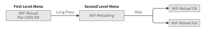
PF Power Curve Mode
PF power curve mode can be modified by Calibrate communication method, according to the set range to set the corresponding value.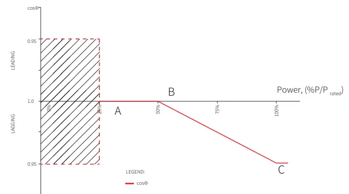
| Function PF curve mode enable or disable | Default value (Australia) 0 | Default value (New Zealand) 0 | Setting range “0”or“1” |
| B %P/P | 50 (50%) | 50 (50%) | 30%~80% |
| C Powerrafteadctor | 0.9 | 0.9 | 0.8~1 |
PU Curve Mode
The PU curve mode can be modified by Calibrate communication method, according to the set range to set the corresponding value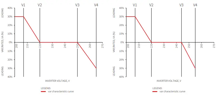
| Function PU curve mode enable or disable | Default value (Australia) 1 | Default value (New Zealand) 1 | Setting range ““0”or“1” |
| V1 voltage ratio | 207V | 207V | Not applicable |
| P1 power ratio | 100 100%*Pn | 100 100%*Pn | 0~120 |
| V2 voltage ratio | ( ) 220V | ( ) 220V | 216V~230V |
| P2 power ratio | 100 100%*Pn | 100 100%*Pn | 0~120 |
| V3 voltage ratio | ( ) 250V | ( ) 244V | 235V~255V |
| P3 power ratio | 100 100%*Pn | 100 100%*Pn | 0~120 |
| V4 voltage ratio | ( ) 265V | ( ) 255V | 244V~265V |
| P4 power ratio | 20 20%*Pn | 20 20%*Pn | 0~120 |
| ( ) | ( ) | ||
QU Curve Mode
QU curve mode can be modified by Calibrate communication, according to the set range to set the corresponding value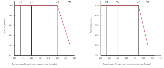
| Function QU curve mode enable or disable | Default value QU curve 0 (Australia) | Mode Default value (New Zealand) 0 | Setting range “0”or“1” |
| V1 voltage ratio | 207V | 207V | Not applicable |
| Q1 reactive power ratio | 30 30%*Pn | 30 30%*Pn | 0~60 |
| V2 voltage ratio | ( ) 220V | ( ) 220V | 216V~230V |
| Q2 reactive power ratio | 0 0%*Pn | 0 0%*Pn | 0 |
| V3 voltage ratio | ( ) 250V | ( ) 244V | 235V~255V |
| Q3 reactive power ratio | 0 0%*Pn | 0 0%*Pn | 0 |
| V4 voltage ratio | ( ) 265V | ( ) 255V | 244V~265V |
| Q4 reactive power ratio | 30 30%*Pn | 30 30%*Pn | 0~60 |
| (- ) | (- ) | ||
Power Recovery Rate
The power recovery rate can be modified by Calibrate communication, according to the set range to set the corresponding value
| Function Power recovery rate Settings | The default value (Australia & New Zealand) 16(16%Pn/min) | Setting range 5~100 |
Troubleshooting
If the Inverter is not able to work properly, please refer to the following instructions before contacting your local service. If any problems arise, the red (FAULT) LED indicator on the front panel will light up and the LCD screen will display relevant information. Please refer to the following table for a list of error message and associated solutions
| Type of fault | Troubleshooting | |
|
System Failure | Isolation Failure | 1. Disconnect DC switch, take off DC connector, check the impedance between 2.PV (+) & PV(-) to earth. 100 kΩ, please check the insulation of PV string If impedance is less than 3.wiring to earth. large than 100 kΩ, please contact local service office. 4.If impedance is measure the impedance between neutral Take off AC connector, |
| Ground I Failure | 1. The ground current is too high. 2.Unplug the inputs from the PV generator and check the peripheral AC 3.system. problem is cleared, reconnect the PV panel and check the Inverter When the 4.status. local service office for help if the problem still persist. Contact | |
| Vac Failure | 1. The PV Inverter will automatically restart within 5 minutes if the grid returns 2.to normal. grid voltage conforms with the specification. 3.Make sure neutral (N) wire and PE wire are connected well. 4.Make sure service office for help if the problem still persist. Contact local | |
| Fac Failure | 1. Grid is not connected. 2.Check grid connection cables. 3.Check availability of grid. | |
| Utility Loss | 1. Not connect to the grid. 2.Check if the power grid is connected to cable. 3.Check the availability of power grid. | |
| PV Over Voltage | 1. Check if the PV open circuit voltage is higher or too close to the maximum 2.input voltage or not. when PV voltage is less than the maximum input If the problem still persist voltage, contact local service office for help. | |
| Over Temperature | 1. The internal temperature is higher than normal value specified. 2.Reduce ambient temperature. 3.Move the inverter to a cool place. 4.If the problem still exists, contact local service office for help. | |
| Type of fault | Troubleshooting | |
|
Inverter Failure | Relay-Check Failure |
1. Turn off DC switch of the inverter. 2.Wait till the inverter’s LCD light is off. 3.Turn on DC switch and make sure it is connected. 4.If the problem still exists, contact local service office for help. |
| DCI Injection High | ||
| EEPROM R/W Failure | ||
| SCI Failure | ||
| SPI Failure | ||
| DC BUS High | ||
| BUS Unbalance | ||
| GFCI Failure | ||
| Ifan Fault | ||
| Efan Fault | ||
| Afan Fault | ||
| No display | 1. Turn off DC switch, take off DC connector, measure the voltage of PV array. 2.Plug in DC connector, and turn on DC switch. 3.If PV array voltage is lower than 250V , please check configuration of inverter 4.module. is higher than 250V , please contact local office. If voltage | |
| Others | Wi-Fi module fail to connect to network | 1. If the Wi-Fi module fail to connect to network after choosing the right router hotspot and entering the right passwords,it’s possible that there are special characters not supported by module in the hotspot passwords. Please modify the password to consist of only Arabic numerals or uppercase / lowercase 2.letters. still exists, contact local service office for help. If the problem |
Maintenace
DC Switch Check
- The DC switch does not need extra maintenance if it’s in use. Just check whether it can work properly.
- Keep the inverter shutdown before checking.
- Turn the DC switch on and off 10 times continually once a year.
- Turn the switch regularly can clean up the device and extend its service life.
Boot order
- Set the circuit breaker on the AC side to ON.
- Set the DC switch to ON.
- Set the circuit breaker on the DC side to ON.
Shutdown order
- Set the circuit breaker on the AC side to OFF.
- Set the DC switch to OFF.
- Set the circuit breaker on the DC side to OFF.
Electrical connection check
- Maintenance period: once a half year.
- Check whether the cables are securely connected.
- Check whether the PE cables are reliably grounded
- Check whether the waterproof covers for ports are locked.
Technical Parameters
| Technical Data GW700-XS GW1000-XS GW1500-XS GW2000-XS Input Max.Input Power (W) 910 1300 1950 2600 | ||||
| Max.Input Voltage(V) | 500 | 500 | 500 | 500 |
| MPPT Operating Voltage Range (V) | 40~450 | 40~450 | 50~450 | 50~450 |
| MPPT Voltage Range at NominalPower (V) | 80~450 | 85~450 | 125~450 | 165~450 |
| Start-up Voltage (V) | 40 | 40 | 50 | 50 |
| Nominal Input Voltage (V) | 360 | 360 | 360 | 360 |
| Max. Input Current per MPPT (A) | 12.5 | 12.5 | 12.5 | 12.5 |
| Max. Short Circuit Current per MPPT (A) | 15.6 | 15.6 | 15.6 | 15.6 |
| Max.Backfeed Current to The Array(A) | 0 | 0 | 0 | 0 |
| Number of MPPT | 1 | 1 | 1 | 1 |
| Number of Strings per MPPT | 1 | 1 | 1 | 1 |
| Output | ||||
| Nominal Output Power (W) 700 1000 1500 2000 | ||||
| Nominal Output Apparent Power (VA) | 700 | 1000 | 1500 | 2000 |
| Max. AC Active Power (W) | 800 | 1100 | 1650 | 2200 |
| Max. AC Apparent Power (VA) | 800* | 1100* | 1650* | 2200* |
| Nominal Output Voltage (V) | 230 | 230 | 230 | 230 |
| Nominal AC Grid Frequency (Hz) | 50/60 | 50/60 | 50/60 | 50/60 |
| Current (A) | 3.5 | 4.8 | 7.2 | 9.6 |
| Max. Output Fault Current(peak and | ||||
| dInurruasthioCnu) r(rAe/nmt(sp)eak and duration) | 25/5 | 25/5 | 25/5 | 25/5 |
| (A/us) Nominal Output Current (A) | 50/2 3 | 50/2 4.3 | 50/2 6.5 | 50/2 8.7 |
| Output Power Factor | ~1 (Adjus | table from 0.8 | leading to 0.8 | lagging) |
| Max. Total Harmonic Distortion | <3% | |||
| Efficiency | ||||
| Max. Efficiency 0.972 0.972 | 0.973 | 0.975 | ||
| European Efficiency | 0.96 | 0.964 | 0.966 | 0.97 |
| Protection | ||||
| DC Insulation Resistance Detection | Integ | rated | ||
| Residual Current Monitoring Unit | Integrated | |||
| Anti-islanding Protection | Integrated | |||
| AC Overcurrent Protection | Integrated | |||
| AC Short Circuit Protection | Integrated | |||
| AC Overvoltage Protection | Integrated | |||
| DC Switch | Integrated | |||
| DC Surge Arrester | ||||
| AC Surge Arrester | Type III | |||
| General Data | ||||
| Operating Temperature Range (℃) -25~60 | ||||
| Relative Humidity | 0~100% | |||
| Max. Operating Altitude (m) | ≤4000 | |||
| Cooling Method | Natural Convection | |||
| Technical Data GW700-XS GW1000-XS GW1500-XS GW2000-XS General Data LED+LCD/WiFi+APP/Bluetooth+APP Display | ||||
| Communication | WiFi / LAN / RS485 | |||
| Communication Protocol | Modbus | |||
| Weight (Kg) | 5.8 | |||
| Dimension (W×H×Dmm) | 295×230×113 | |||
| Noise Emission (dB) | 25 | |||
| Topology | Transformerless | |||
| Night Power Consumption (W) | <1 | |||
| Ingress Protection Rating | IP65 | |||
| DC Connector | MC4( 2.5~4mm²) | |||
| AC Connector | plug and play connector | |||
| Environmental Category | 4K4H | |||
| Pollution Degree | III | |||
| Overvoltage Category | DC II / AC III | |||
| Protective class | Class I | |||
| The Decisive Voltage Class (DVC) | C | |||
| Technical Data GW2500-XS GW3000-XS GW2500N-XS GW3000N-XS Input Max.Input Power (W) 3250 3900 3250 3900 | ||||
| Max.Input Voltage(V) | 500 | 500 | 600 | 600 |
| MPPT Operating Voltage Range (V) | 50~450 | 50~450 | 50~550 | 50~550 |
| MPPT Voltage Range at NominalPower (V) | 205~450 | 245~450 | 200~450 | 240~450 |
| Start-up Voltage (V) | 50 | 50 | 50 | 50 |
| Nominal Input Voltage (V) | 360 | 360 | 360 | 360 |
| Max. Input Current per MPPT (A) | 12.5 | 12.5 | 13 | 13 |
| Max. Short Circuit Current per MPPT (A) | 15.6 | 15.6 | 16.3 | 16.3 |
| Max.Backfeed Current to The Array(A) | 0 | 0 | 0 | 0 |
| Number of MPPT | 1 | 1 | 1 | 1 |
| Number of Strings per MPPT | 1 | 1 | 1 | 1 |
| Output | ||||
| Nominal Output Power (W) 2500 3000 2500 3000 | ||||
| Nominal Output Apparent Power (VA) | 2500 | 3000 | 2500 | 3000 |
| Max. AC Active Power (W) | 2750 | 3300 | 2750 | 3300 |
| Max. AC Apparent Power (VA) | 2750* | 3300* | 2750* | 3300* |
| Nominal Output Voltage (V) | 230 | 230 | 220/230 | 220/230 |
| Nominal AC Grid Frequency (Hz) | 50/60 | 50/60 | 50/60 | 50/60 |
| Current (A) | 12 | 14.3 | 12 | 14.3 |
| Max. Output Fault Current(peak and | ||||
| dInurruasthioCnu) r(rAe/nmt(sp)eak and duration) | 30/5 | 30/5 | 30/5 | 30/5 |
| (A/us) Nominal Output Current (A) | 50/2 | 50/2 13 | 50/2 11.4/10.9 | 50/2 13.6/13 |
| Output Power Factor | 10~.91 (Adjus | table from 0.8 | leading to 0.8 | lagging) |
| Max. Total Harmonic Distortion | <3% | |||
| Technical Data Efficiency Max. Efficiency | GW2500-XS GW3000-XS GW2500N-XS GW3000N-XS 0.976 0.976 0.976 0.976 | ||||
| European Efficiency | 0.972 | 0.972 | 0.972 | 0.972 | |
| Protection | |||||
| DC Insulation Resistance Detection | Integrated | ||||
| Residual Current Monitoring Unit | Integrated | ||||
| Anti-islanding Protection | Integrated | ||||
| AC Overcurrent Protection | Integrated | ||||
| AC Short Circuit Protection | Integrated | ||||
| AC Overvoltage Protection | Integrated | ||||
| DC Switch | Integrated | ||||
| DC Surge Arrester | Type III Type III(Type II Optional) | ||||
| AC Surge Arrester | Type III | type III type III | |||
| DC Arc Fault Circuit Interrupter | NA NA | Optional | Optional | ||
| General Data | |||||
| Operating Temperature Range (℃) | -25~60 | ||||
| Relative Humidity | 0~100% | ||||
| Max. Operating Altitude (m) | ≤4000 | ||||
| Cooling Method | Natural Convection | ||||
| Display | LED+LCD/WiFi+APP/Bluetooth+APP | ||||
| Communication | WiFi / LAN / RS485 RS485 / WiFi | ||||
| Communication Protocol | Modb | us | |||
| Weight (Kg) | 5.8 | ||||
| Dimension (W×H×Dmm) | 295×230×113 | ||||
| Noise Emission (dB) | 42 | ||||
| Topology | Transformerless | ||||
| Night Power Consumption (W) | <1 | ||||
| Ingress Protection Rating | IP65 | ||||
| DC Connector | MC4( 2.5~4mm²) | ||||
| AC Connector | plug and play connector | ||||
| Environmental Category | 4K4H | ||||
| Pollution Degree | III | ||||
| Overvoltage Category | DC II / AC III | ||||
| Protective class | Class I | ||||
| The Decisive Voltage Class (DVC) | C | ||||
| Technical Data GW3KB-XS GW3300-XS Input Max.Input Power (W) 3900 3900 | ||
| Max.Input Voltage(V) | 600 | 500 |
| MPPT Operating Voltage Range (V) | 50~550 | 50~450 |
| MPPT Voltage Range at NominalPower (V) | 240~450 | 275~450 |
| Start-up Voltage (V) | 50 | 50 |
| Nominal Input Voltage (V) | 360 | 360 |
| Max. Input Current per MPPT (A) | 13 | 12.5 |
| Max. Short Circuit Current per MPPT (A) | 16.3 | 15.6 |
| Max.Backfeed Current to The Array(A) | 0 | 0 |
| Number of MPPT | 1 | 1 |
| Number of Strings per MPPT | 1 | 1 |
| Output | ||
| Nominal Output Power (W) 3000 3300 | ||
| Nominal Output Apparent Power (VA) | 3000 | 3300 |
| Max. AC Active Power (W) | 3300 | 3300 |
| Max. AC Apparent Power (VA) | 3300 | 3300 |
| Nominal Output Voltage (V) | 220 | 230 |
| Nominal AC Grid Frequency (Hz) | 60 | 50/60 |
| Current (A) | 14.3 | 14.3 |
| Max. Output Fault Current(peak and | ||
| dInurruasthioCnu) r(rAe/nmt(sp)eak and duration) | 30/5 | 30/5 |
| (A/us) Nominal Output Current (A) | 50/2 13.6/13 | 50/2 14.3 |
| Output Power Factor | ~1 (Adjustable from 0.8 | leading to 0.8 lagging) |
| Max. Total Harmonic Distortion | <3% | |
| Efficiency | ||
| Max. Efficiency 0.976 | 0.976 | |
| European Efficiency | 0.972 | 0.972 |
| Protection | ||
| DC Insulation Resistance Detection | Integr | ated |
| Residual Current Monitoring Unit | Integrated | |
| DC Reverse Polarity Protection | N/A Integrated | |
| Anti-islanding Protection | Integr | ated |
| AC Overcurrent Protection | Integrated | |
| AC Short Circuit Protection | Integrated | |
| AC Overvoltage Protection | Integrated | |
| DC Switch | Integrated | |
| DC Surge Arrester | Type III | |
| AC Surge Arrester | Type III | |
| DC Arc Fault Circuit Interrupter | Optional | |
| General Data | ||
| Operating Temperature Range (℃) | ﹣25~60 -25~60 | |
| Relative Humidity | 0~100% | 0~100% |
| Max. Operating Altitude (m) | ≤4000 | ≤3000 |
| Cooling Method | Natural Convection | Natural Convection |
| Technical Data GW3KB-XS GW3300-XS General Data LED+LCD/WiFi+APP/Bluetooth+APP Display | ||
| Communication | RS485 / WiFi WiFi / LAN / RS485 | |
| Communication Protocol | Modb | us |
| Weight (Kg) | 5.8 | |
| Dimension (W×H×Dmm) | 295×230×113 | |
| Noise Emission (dB) | 42 | |
| Topology | Transformerless | |
| Night Power Consumption (W) | <1 | |
| Ingress Protection Rating | IP65 | |
| DC Connector | MC4( 2.5~4mm²) | |
| AC Connector | plug and play connector | |
| Environmental Category | 4K4H | |
| Pollution Degree | III | |
| Overvoltage Category | DC II / AC III | |
| Protective class | Class I | |
| The Decisive Voltage Class (DVC) | C | |
Overvoltage Category Definition
- Category I: applies to equipment connected to a circuit where measures have been taken to reduce transient overvoltage to a low level.
- Category II: applies to equipment not permanently connected to the installation. For example, appliances, portable tools and other plug-connected equipment;
- Category III: applies to fixed downstream equipment, including the main distribution board. For example,switchgear and other equipment in an industrial installation;
- Category IV: applies to equipment permanently connected at the origin of an installation
(upstream of the main distribution board). For example, electricity meters, primary overcurrent protection equipment and other equipment connected directly to outdoor open lines
Moisture Location Category Definition
| Moisture parameters | |||
| 0~3+K403℃ | L4eKv2el -33~+40℃ | -204~K+45H5℃ | |
| TeHmumpeidraittyuRreaRnagnege | 5%~85% | 15%~100% | 4%~100% |
Environment Category Definition
- Outdoor : the ambient air temperature is -20~50℃. Relative humidity range is from 4% to 100%, applied to PD3.
- Indoor unconditioned: the ambient air temperature is -20~50 ℃. Relative humidity range is from 5% to 95%, applied to PD3.
- Indoor conditioned: the ambient air temperature is 0~40 ℃. Relative humidity range is from 5% to 85%, applied to PD2.
Pollution Degree Definition
- Pollution degree 1: No pollution or only dry, non-conductive pollution occurs. The pollution has no influence.
- Pollution degree 2: Normally only non-conductive pollution occurs. However, a temporary conductivity occasionally caused by condensation must be expected.
- Pollution degree 3: Conductive pollution occurs. Or dry, non-conductive pollution becomes conductive due to condensation, which is expected.
- Pollution degree 4: Persistent conductive pollution occurs. For example, the pollution cause by conductive dust, rain and snow.


