
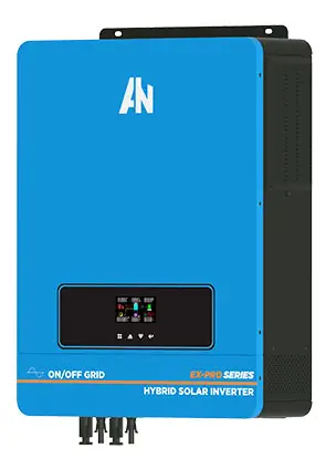
Anern AN-MPSG MPPT Hybrid Solar Inverter
Dear Customers:
It’s very grateful to you for trusting our company and selecting our products! Before using this product, please read carefully this user manual, including installation, using, failure investigation and other important information and suggestion, we also suggest you keep this manual well!
Product features
Double CPU intelligent control technology, performance excellence;
- The power mode / energy saving mode / battery mode can be set up, Flexible application;
- Smart fan control, safe and reliable;
- The pure sine wave output, can adapt to various types of load;
- Wide input voltage range,high-precision output automatic voltage function.
- The LCD real-time display device parameters, running status at a glance;
- The output overload, short circuit protection, automatic protection and alarm;
- The intelligent MPPT solar controller, overcharge,overdischarge protection, current limiting charging, multiple protection;
Installation, storage instructions
Off packet inspection
- open the packaging of the equipment, please check the product parts, including: a mainframe, the use of a manual.
- check whether the equipment is damaged in transit, such as damage or missing parts, do not boot, inform the carrier and dealer.
Installation, storage precautions
- Installation equipment should be operated by professionals, or assisted by local distributors.
- Transport equipment, the need to take appropriate protective measures; equipment from low temperature to high temperature environment, may appear drops, before using, need to be completely dry, to ensure safety.
- Don’t expose the device in the wet, inflammable, explosive or a lot of dust accumulation in the bad environment; do not cover and block the vents, 10cm above the air circulation space reserved for peripheral equipment; in order to have good heat dissipation;
- When the equipment is not in use,it should close all switches;
Inverter diagram, operation instructions
Side panel icon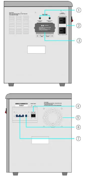
Front panel icon
 Guide
Guide
- AC input/outputfuse holder
- AC Output
- AC input/output termianl
- Solar input port
- Fan
- Solar input breaker
- Battery input breaker
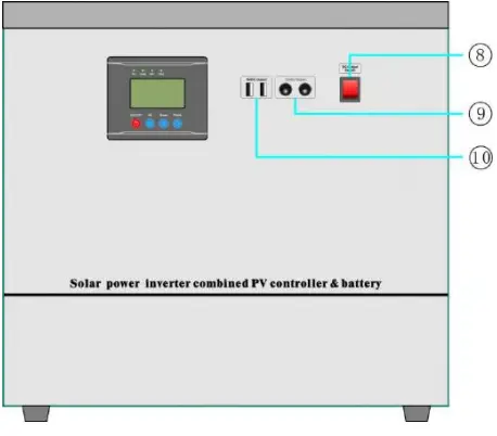
- 5VDC-USB、12VDCoutput ON/OFF switch
- 12VDC Output:12VDC-USB output terminal
- 5VDC Output:5VDCoutput terminal
Front panel instructions
LCD display and function key operation interface, can display the working status of the equipment, such as: Input / output voltage, frequency, mains mode, the inverter mode, battery capacity, charge current, charge the total load capacity, warning tips;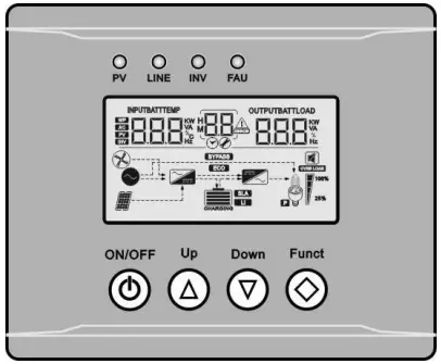
Keys Description
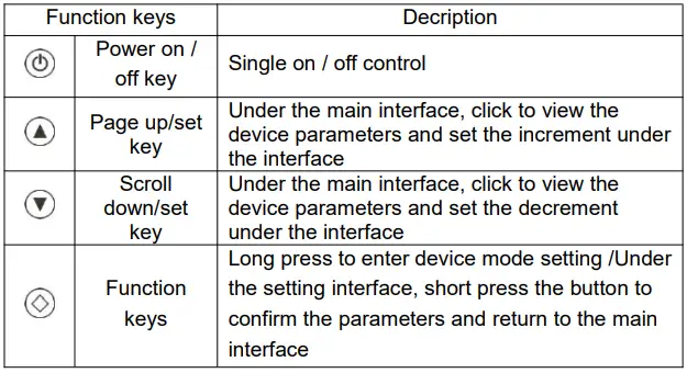
LED Status Description
| LED display | Description | ||
| PV | Green | Quick Flash | Maximum power tracking mode charge |
| Slow Flash | Floating charging mode | ||
| OFF | Stop charging | ||
| LINE | Green | Light | The AC is connected and the output is bypassed |
| OFF | Do not connect AC power or it is in inversion state | ||
| INV | yellow | Light | The device is in inversion state |
| OFF | The device is not in inversion state | ||
| FAU | red | Light | Device AC output short circuit or severe overload |
| OFF | The device work normally | ||
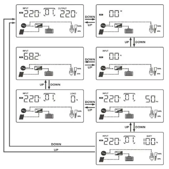
- LCD display instruction
- View the main interface:In the main interface, press DOWN or UP to scroll through the screen.

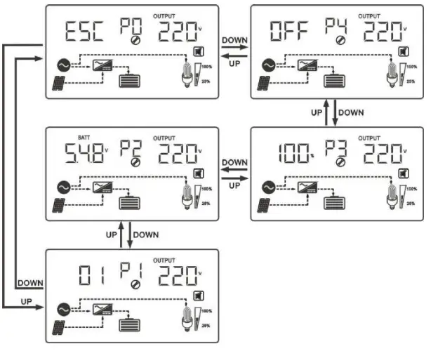
Main menu: in the main interface, long press Funct key for 5 seconds or less to enter the main menu, and press DOWN or UP to view the sub-menu. The function of P0/P1/P2/P3/P4 in the flashing state is as follows:
| Main Menu | Functions |
| P4 | Buzzer mode |
| P3 | Inverter charging current |
| P2 | Inverter charging voltage |
| P1 | Inverter operating mode |
| P0 | Save & Exit |
ParametersSetting
Buzzer mode Settings Under the main interface, long press the Funct button for 5 seconds or less to enter the main menu, press the DOWN button to select the buzzer information P4, press the Funct button to enter the setting interface, turn on/off the buzzer state through DOWN or UP key, and press the Funct key to save and exit. On Indicates that the buzzer is on; 0FF Indicates that the buzzer is off;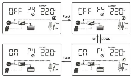
Inverter charging current setting
Under the main interface, long press the Funct button for 5 seconds or less to enter the main menu. Press the DOWN button to select the inverter charging current information P3. Press the Funct button to enter the setting interface . Through DOWN or UP keys, increase /decrease The charge current of the inverter (100%-80%-60%-40%-20%). Pressed Funct to save and exit.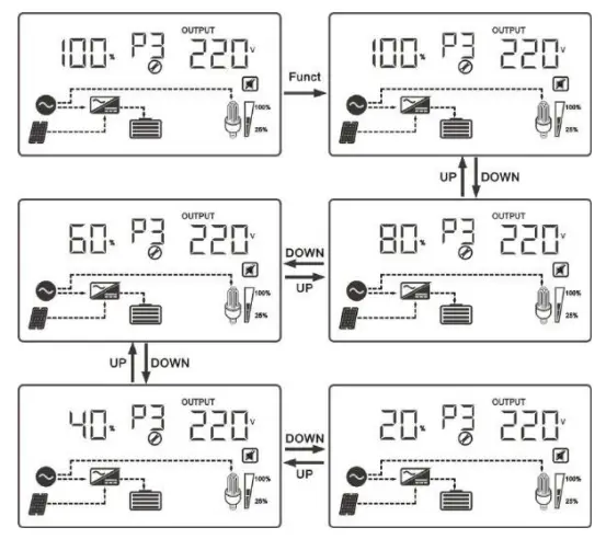
| Charging voltage value | Voltage type |
| 54.8 | Gel U.S.A |
| 53.6 | A.G.M.1 |
| 54.8 | A.G.M.2 |
| 55.2 | Gel European |
| 55.2 | Open lead acid |
| 54.4 | Calcuim(open) |
| 58.0 | De sulphation cycle 15.5 for 4 hrs |
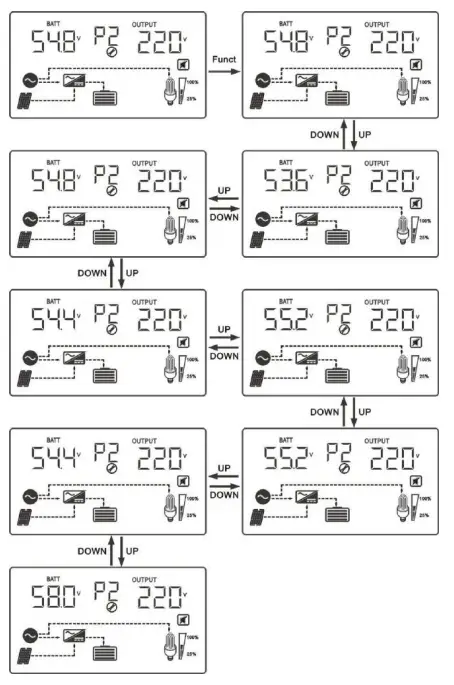
Inverter charging voltage setting
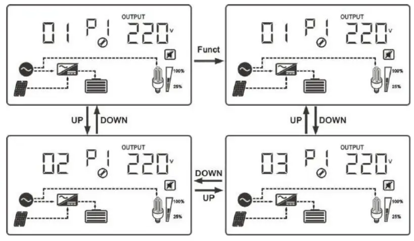
Under the main interface, long press the Funct key for 5 seconds or less to enter the main menu, press the DOWN key to select the inverter work mode information P1, press the Funct key to enter the setting interface, adjust the inverter work mode (01-02-03) through DOWN or UP key, press the Funct key to save and exit.
| con | Working mode | Running state |
|
01 |
The grid priority mode | Mains priority mode, after the device starts and the grid input under normal operation, the equipment through the grid bypass regulator to supply power to the load, at the same time power battery;When the grid is having too high/low/serious distortion or other abnormal , equipment will make battery energy through internal module transfer into high quality electricity and supply power to load. |
|
02 |
Energy-s aving mode | Under energy-saving mode, after the device starts, it will automatically detect load, when the load is greater than 15% rated power, the equipment starts AC output and power to the load; When detects no load, the device will automatically back to the search pattern, drop the battery energy consumption to lowest; This mode, equipment detects load every 15s, so as to achieve the purpose of energy saving. |
|
03 | Battery priority mode | Battery priority mode, When the battery in the external charging device (such as solar charging system) after adequate power charged, equipment will automatically convert to battery energy through internal module into high quality electricity for load;When the |
Device connection icon
Recommended line diameter
Battery, AC input / output connecting wire diameter recommended that: (1 mm2 copper wire is calculated by current 4-5A)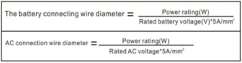
For example: 5000W/48VDC/220VAC equipment connecting wire diameter are as follows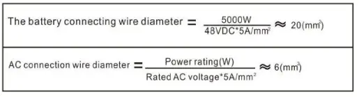
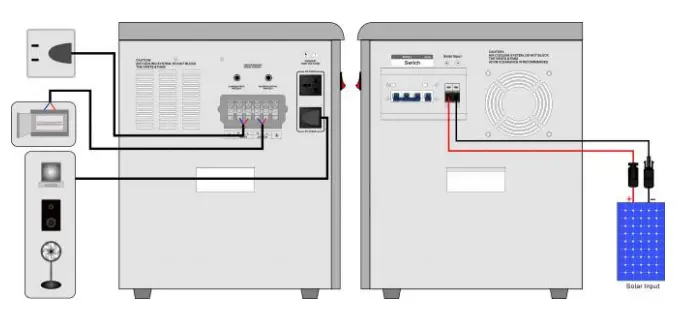
Input/Output wiring diagram
Photovoltaic module access instructions
After connecting the photovoltaic module with a suitable wire diameter, make sure that the voltage and power are within the rated range, and connect it to the “④–Solar input port ” on the side panel of the equipment. Pay attention to the polarity error in the connection process of the photovoltaic module, so as not to damage the equipment.
Mains access instructions
Select the right diameter of the wire to connect the power supply to the side board of the equipment on the “③– AC input termianl “;Note that the input ac voltage should be within the input range of the equipment to avoid damage the equipment .
Notes of output load
The load of 220VAC is connected to the”②– AC Output”terminal The load power is the rated power of inverter with load detection function and load percentage display.4.6 “⑨–12VDC Output”、“⑩–5VDC Output” Connection introduction4.6.1 Confirm DC load working current can’t exceed the equipment rated current, the two “⑨—12VDC Output”DC terminal port on the front panel foreign respectively with 12 VDC, 1 amp current, two ” ⑩—5VDC Output ” dc port foreign respectively provide 5 VDC, 1 amp of current; 4.6.2 When access dc load, note its polarity can’t be wrong, it is strictly prohibited the dc port output wiring short circuit, so as not to damage the equipment;
Power ON/RUN
Note: Check it the voltage of battery psck and polarity of the solar module are connected to the equipment correctly.
Inverter Power ON/RUN
Battery starting pull the battery breaker on the side panel to the closed state. Long press the “ON / OFF” button on the front panel for 2 seconds, release it after the buzzer beeps once .The “INV” indicator light, automatically open the inverter output.
Mains Input Power-on
enter appropriate mains power, the front board “LINE” indicator light, the device automatically output
Photovoltaic controller Charger-Disable
Connect to the photovoltaic module, unplug the solar energy input circuit breaker on the side panel of the equipment to the closed state. When the solar module is exposed to sunlight, the “PV” indicator light on the front panel will light up. At this time, the controller is already in the charging state, and the photovoltaic module will supplement the battery power through the controller;
Equipment shutdown
Shutdown: Turn off the load one by one, disconnect the mains input, and then press the “power on / off button” for 2 seconds, release after the internal relay action, the device off the AC output, LCD screen goes out, pull the side panel of the circuit breaker to disconnect the state;
OPERATION PRECAUTIONS: When opening the device, follow the following sequence: first close the circuit breaker of the battery, and then close the circuit breaker of the solar module input. When the device is turned off, disconnect the circuit breaker of the solar module input, then disconnect the battery of a circuit breaker;
Caution: When disconnecting the solar module, please leave the battery breaker on the side panel to the off state to avoid the deep discharge of the battery when the device is not used for a long time. The internal controller in the standby power loss);
Battery protection voltage of the inverter Introduction / Parameter table
When the AC output is turned on, the relevant protection or indication will be executed when the battery voltage reaches the value in the table below.
| Inverter battery protection voltage parameter table-12V; * A (Battery segment) | ||||
| Overvoltage protection | Overvoltage recovery | Undervoltage recovery | Undervoltage alarm | Undervoltage protection |
| 16.8;*A | 16;*A | 13.5;*A | 10.5;*A | 10.3;*A |
| Close the AC output | Restore AC output | Restore the inverter AC output | Maintain AC output | Utility bypass Mains charge |
Audible alarm reminder instruction
|
Equipment running normal | Buzzing prohibit | Buzzer is no tweet under default state |
| Buzzer starts | Buzzer tweet 4 times every 15s, indicate the equipment operated under battery inverter state | |
| Battery high voltage alarm | Buzzer tweets 4 times per second, alarms high voltage | |
| Battery low voltage alarm | Buzzer tweets 2 times per second, alarms low voltage | |
| Over temperature alarm | Buzzer alarm 2 seconds pause 1 second | |
Electric generator connection announcements:
If connect electric generator, it needs operating as below:
- Start up electric generator and after it running stable, make electric generator output power supply be connected into the equipment input terminal, then make sure the equipment output is no-load, then start up the equipment.
- After the equipment starting, then connect load one by one
- We suggest electric generator capacity should be 2~3 times of this equipment
Maintenance and maintenance
- This series of products with little maintenance, battery only need to constantly maintain the charge to obtain life expectancy. In the same city electricity connection.
- If you do not use the equipment for a long period of time, it is recommended to charge it every 4-6 months. Under normal circumstances, the battery’s life will be 3-5 years, if found in poor condition, you must replace the battery early. When replacing the battery, it must be carried out by qualified personnel. Battery should not be individually replaced, the overall replacement should follow the battery supplier’s instructions.
- Normal use, the battery every 4 to 6 months to be charged, discharge time, discharge to the shutdown charge, In the high temperature region, the battery charge every two months, discharge time.
- Before replacing the battery, turn off the device and disconnect it from the mains, and close the battery switch. Take off metal objects such as rings and watches. Use insulated handle and screwdriver, do not put tools or other metal objects on the battery pack.
- When connecting the battery cable, it is normal for small sparks to appear in the joint, which will not cause any harm to the personal safety and the equipment. Do not charge the battery positive and negative, very short or reverse connection.
Simple fault diagnosis and treatment
WARNING: There is high pressure inside the machine! Do not open and try to repair or maintenance, so as not to cause electric shock hazard!
| Failure phenomenon | Possible reason | solution |
|
The machine load time is reduced | The battery is not fully charged | Make sure that the battery is fully charged |
| The machine connection is overloaded | Removal of noncritical loads | |
| Battery aging, can not be sufficient power | Contact your customer service representative to obtain a battery replacement kit | |
| The device can not be turned on | The mains input cable or the battery cable is poorly connected | Check and reconnect |
| Boot alarm | The battery is low | Make sure that the battery is fully charged |
| Load overload | Removal of noncritical loads | |
| The buzzer is called 2 seconds and 1 second | The internal temperature is too high alarm | Check the fan and cooling holes are blocked |
| The fan is spinning slowly | The fan adjusts according to the temperature | normal phenomenon |
| The “PV” indicator does not light when there is a sun-lit PV module | PV module array cable open | Please check whether the wiring of the PV array is correct and the contact is reliable |
When you contact the service personnel, please provide the following information: Type of machine / date of issue / complete description of the problem (including the relevant indicator display status, battery configuration, connection and other information).
Technology parameter sheet
| Model | AN-MPSG | ||
| Battery rated voltage(vdc) | 24V | 48V | |
|
Inverter | Rated power(w) | 3000 | 5000 |
| Input voltage range(vac) | 85-138VAC/140-275VAC | ||
| Input frequency(Hz) | 45-65 | ||
| Output voltage(vac) | 110/220 | ||
| Output frequency(Hz) | 50/60 | ||
| Output wave | Pure Sine Wave | ||
| Speficifation of built-in battery | 2600WH | 4500WH | |
|
MPPT Solar input | MPPT Voltage Range | 30-150VDC | 60-150VDC |
| PV Power | 1600W | 1600W | |
| Rated charge current | 60A | 30A | |
| MPPT efficiency | ≥99% | ||
| Floating charge voltage | 25.2VDC | 50.4VDC | |
| Low voltage recovery voltage | 23.4VDC | 44VDC | |
| Low voltage protecton voltage | 18.6VDC | 36VDC | |
| 5VDC USB output | 2 个/MAX 2A | ||
| 12VDC output ports | 2 个/MAX 2A | ||
| Heat dissipation/Cooling | Temperature control by intelligent exhaust fan | ||
| Operating ambient temperature | -20 – +50℃ | ||
| Storage ambient temperature | -25 – +55℃ | ||
| Operating/Storage ambient | 0-90% No condensation | ||
| External size:W*D*H(mm) | 538*329*529mm | 620*420*580mm | |
| Package size:W*D*H(mm) | 635*420*700mm | 720*520*761mm | |
Note: Our company has the right of changing this user manual without any information


