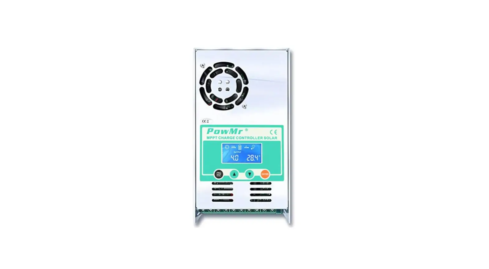
PowMr MPPT- 60A Solar Charge Controller
Important Safety Instructions
Please save these instructions
This manual contains important safety, installation, and operating instructions for the charge controller. The following symbols are used throughout the manual to indicate potentially dangerous conditions or important safety information.
WARNING
Indicates a potentially dangerous condition. Use extreme caution when performing this task
CAUTION
Indicates a critical procedure for safe and proper operation of the controller
NOTE
Indicates a procedure or function that is important to the safe and proper operation of the controller
General Safety Information
- Read all of the instructions and cautions in the manual before beginning the installation.
- There are no serviceable parts for this controller. Do NOT disassemble or attempt to repair the controller.
- Do NOT allow water to enter the controller.
- Make sure all connections going into and from the controller are tight.
Charge Controller Safety
- NEVER connect the solar panel array to the controller without a battery. Battery must be connected first.
- Ensure input voltage does not exceed 190 VDC to prevent permanent damage. Use the Open Circuit Voltage (Voc) to make sure the voltage does not exceed this value when connecting panels together.
Battery Safety
- Use only sealed lead-acid, flooded, gel or lithium batteries which must be deep cycle.
- Explosive battery gases may be present while charging. Be certain there is enough ventilation to release the gases.
- Be careful when working with large lead acid batteries. Wear eye protection and have fresh water available in case there is contact with the battery acid.
- Carefully read battery manuals before operation.
- Do NOT let the positive (+) and negative (-) terminals of the battery touch each other. Recycle battery when it is replaced.
- Over-charging and excessive gas precipitation may damage the battery plates and activate material shedding on them. Too high of an equalizing charge or too long of one may cause damage. Please carefully review the specific requirements of the battery used in the system.
- Equalization is carried out only for non-sealed / vented/ flooded / wet cell lead acid batteries.
- Do NOT equalize VRLA type AGM / Gel / Lithium cell batteries UNLESS permitted by battery manufacturer.
WARNING
- Connect battery terminals to the charge controller BEFORE connecting the solar panel(s) to the charge controller. NEVER connect solar panels to charge controller until the battery is connected.
- Do NOT connect any inverters or battery chargers into the load terminal of the charge controller.
- Once equalization is active in the battery charging, it will not exit this stage unless there is adequate charging current from the solar panel. There should be NO load on the batteries when in the equalization charging stage.
General Safety Information and waiver liability
- Read all of the instructions and cautions in the manual before beginning the installation.
- There are no serviceable parts for this controller. Do NOT disassemble or attempt to repair the controller.
- Make sure all connections going into and from the controller are tight. There may be sparks
- when making connections, therefore, make sure there are not flammable materials or gases near the installation and cool place.
- Red wire connected the positive Pole of the controller and black wire connected the positive Pole of the controller
- Contact us first if you have any questions.
Liability Disclaimer
The manufacturer shall not be liable for damages, especially on the battery, caused by use other than as intended or as mentioned in this manual or if the recommendations of the battery manufacturer are neglected. The manufacturer shall not be liable if there has been service or repair carried out by any unauthorized person, unusual use, wrong installation, or bad system design.
Overview
MPPT series solar charge controller is based on an advanced maximum power point tracking (MPPT) technology developed, dedicated to the solar system ,the charge controller conversion efficiency up to 97%.
It comes with a number of outstanding features, such as:
- MPPT 60A solar charge controller
- 100% MPPT technology
- Built-in DSP controller with high performance
- Automatic switch for 12V/24V/36V/48V battery bank
- stage charging optimizes battery performance
- Overcharge protection, input PV polarity reverse protection .output limited current protection, over-temperature protection
- Troubleshooting promotion function
- Suitable for battery types such as sealed lead acid, vented gel and lithium battery.
- Easy to be mounted
Dimensions
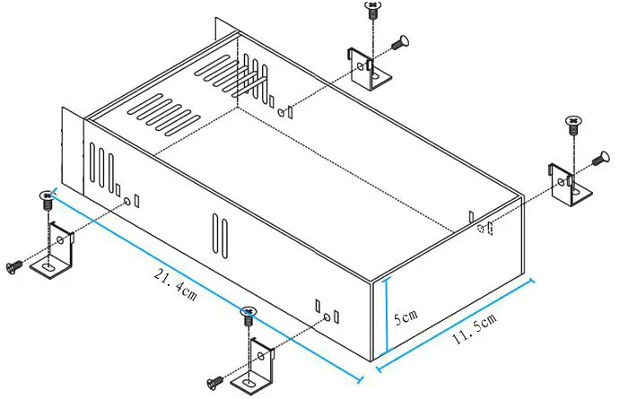
Notes:
Please use our screws only since it damaged the internal PCB if using other screws. Please yes proper torque to push the screws into casing since it may damage the internal PCB by strong torque
Installation
Instruction Notes
1st step: Connect the batteries
Connect the battery connection cable with the correct polarity to the middle pair of terminals on the solar charge controller(with the battery symbol).if the system is 12V, please make sure your battery voltage more than 12V, then the controller can boot up.
2nd step: Connect the solar panel
Ensure that the pv modules is protected from incident light. ensure that the solar panel doesn’t exceed the maximum permissible input current. Connect the pv modules connection cable to the correct polarity of the left pair of terminals on the solar charge controller(with the pv modules symbol).
3rd step: connect loads
Connect the load cable to the correct polarity of the right pair of terminals on the solar charge controller(with the lamp symbol).to avoid any voltage on the wires, please connect the wire to the load before connecting to the controller.
4th step: Final worked
Tight all cables connected to the controller and remove all the debris around the controller(leaving a space of approx. 5.91 in)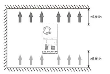
Notes:
When the reading data of PV or battery is constantly changing, don’t worry about it , the controller is finding MPP point, it’s caused by your PV input power or voltage isn’t enough, please contact us soon .our technological team will assist you.
Air circuit Breaker installation
We strongly recommend connecting a fuse directly to the battery to protect any short circuit at the battery wiring. Solar PV modules create current whenever light strikes them. The current created varies with the light intensity, but even in the case of low levels of light, full voltage is given by the modules. So, protect the solar modules from incident light during installation. Never touch uninsulated cable ends, use only insulated tools, and make sure that the wire diameter is in accordance with the expected currents of the solar charge controller. Connections must always be made in the sequence described below.
Air Circuit Breaker and Wires Requirement
| Models | Copper wires | Air circuit breakers |
| MPPT-60A | 6mm²x2PCS | 100A |
Reminder
It’s better to connect two wires to two PV+ and another two wires to two PV-. For BAT+ and BAT-, it’s same way to connect wires.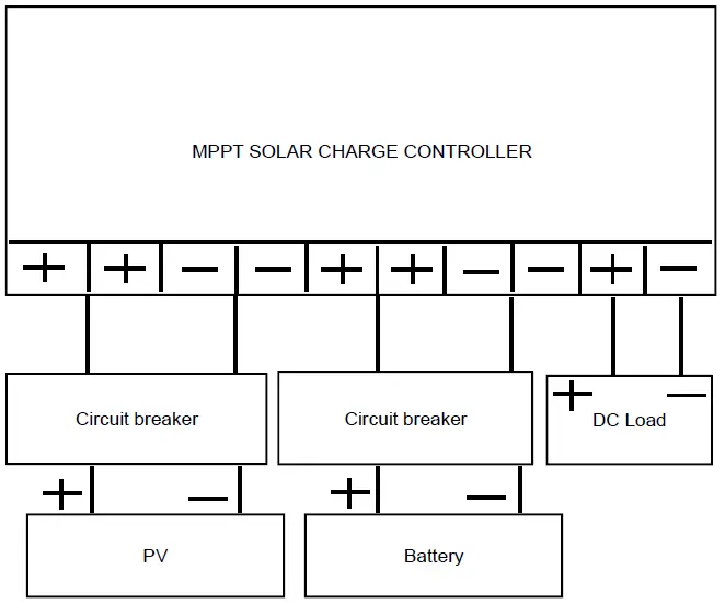
- Install air circuit breaker between controller and batteries. Turn off the circuit breaker, then connect batteries to the controller with the correct polarity.
- Install air circuit breaker between controller and PV modules. Turn off the circuit breaker, and ensure the PV polarity is correct, then connect wires between PV modules and controller.
- Turn on the air circuit breaker between the controller and batteries.
- Turn on the air circuit breaker between the controller and PV modules.
- The controller goes into the self-test mode. Its LCD displays the parameters if all is correct. And RUN lamp (under the fan inside of casing) will flash every one second. If the controller is no respond, please read full manual again for reinstalling or contact us for help.
Operation
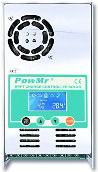
LCD display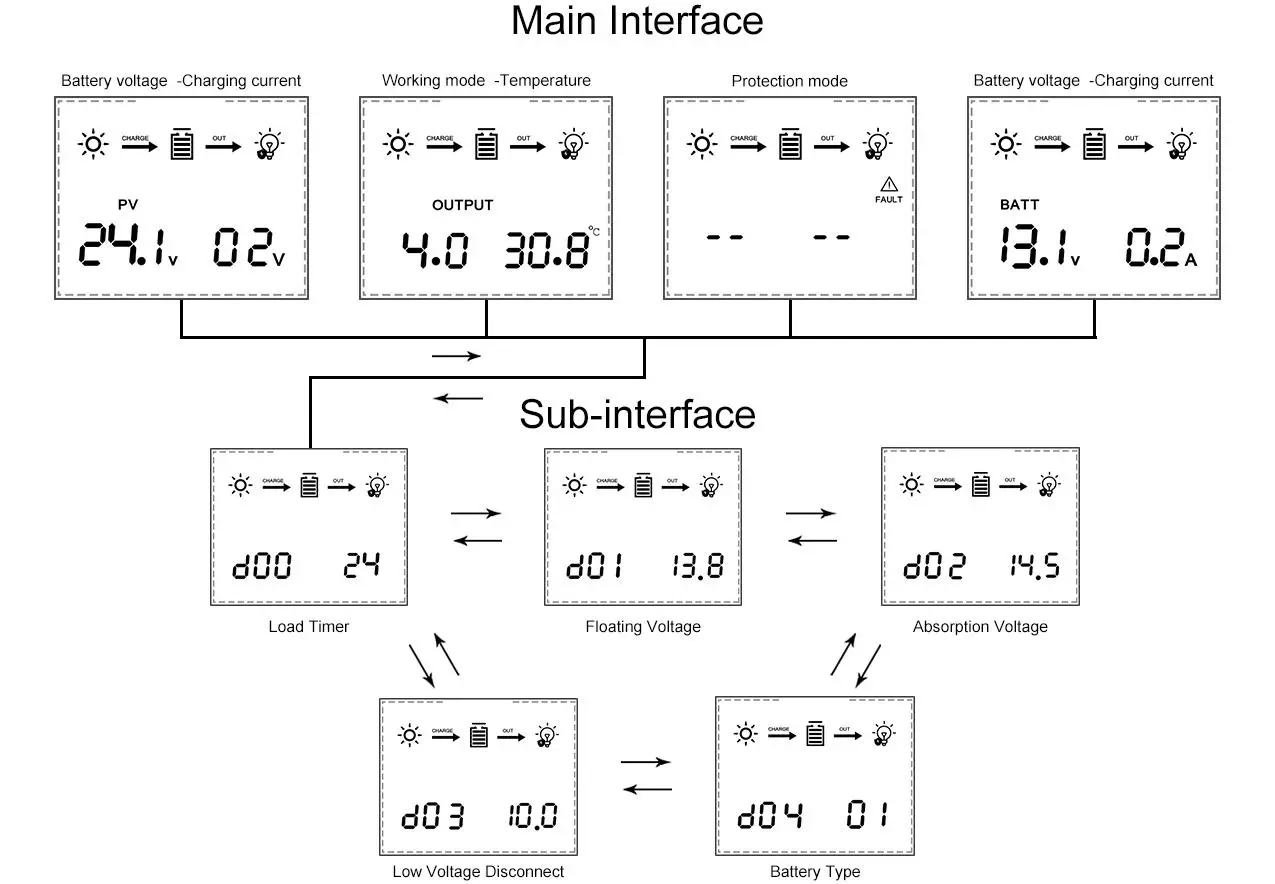
| Item | Description |
| 1 | PV voltage / Output power |
| 2 | Battery voltage / Charging current |
| 3 | Working mode / Temperature |
| 4 | Protection mode |
Working mode
| 3. 0 | Night mode, no charging |
| 4. 0 | MPPT mode |
| 7. 0 | Absorption mode |
| 8. 0 | Floating mode |
Batteries charge voltage reference
| Battery Type | Absorption Voltage ( Constant voltage ) | Floating Voltage | ||||
| 12V | 24V | 48V | 12V | 24V | 48V | |
| Vented | 14.2V | 28.6V | 57.2V | 13.2V | 26.4V | 52.80V |
| Sealed | 14.4V | 28.8V | 57.6V | 13.8V | 27.6V | 55.2V |
| Gel | 14.4 V | 28.8V | 57.6V | 13.8V | 27.6V | 55.2V |
| NiCd | 14.2V | 28.6V | 57.2V | 14.0V | 28.0V | 56.0V |
| Lithium or others | Defined by users | |||||
Manual Setting
Reminder: The controller will work fine under the default setting except for lithium battery.
Caution! All steps must be carried out when the PV modules are disconnected from the controller.
Step 1: D00
Press the button PRG, then LCD displays D00. This is setting for load working time (Default is 24 hours). Press ENT until numbers flash, then press UP/DOWN to set up time that you want, long-press ENT to confirm it. This output voltage is the same as the battery. The load is only for small DC loads less 5A current. If no load, just leave it.
Step 2: D01
Press the button UP, LCD shows 13.8. This is default value of floating charging. Press ENT until numbers flash, then press UP/DOWN to set up voltage that you want, and long-press ENT to confirm it.
Caution!
This value is for one 12V battery. If there are many batteries in series, the controller will multiply them in proportion automatically and the LCD only displays the voltage of one battery (For example, if your battery is 4x12V, and if you set the voltage at 14.1, the charge voltage will be 4×14. 1 automatically, but the LCD only displays 14.1).
Step 3: D02
Continue to press the button UP, LCD shows 14.5. This is highest absorption charging voltage for battery. Press ENT until numbers flash, then press UP/DOWN to set up voltage that you want, long-press ENT to confirm it.
Caution! This value is for one 12V battery. If there are many batteries in series, the controller will multiply them in proportion automatically and the LCD only displays the voltage of one battery.
Step 4: D03
Continue to press the button UP, LCD shows 10.0. This is the protection value of battery discharge. Press ENT until numbers flash, then press UP/DOWN to set up the voltage that you want, and long-press ENT to confirm it. It means it’s protected when 12V battery is less 10. 0V and there is no output power from OU+ and OU-.
Step 5: D04
Continue to press the button UP, LCD shows 00.00 is the default for acid batteries. If it’s for lithium battery, please press ENT until numbers flash, then press UP/DOWN to choose 01, and long-press ENT to confirm it. Step 2 (D01) is no use when you choose 01 for a lithium battery. And the voltage set in step 3 (D02) will be the highest charging voltage for a lithium battery.
Press ESC to exit the setting menu
Reminder:
When you set up all steps, please disconnect the battery. And reconnect the controller to see if all setting is successful. When all setting is ok, then connect PV modules to the controller.
Troubleshooting and Protections
| Code | Description | How to solve |
| 18 | Input PV voltage is low | Increase the PV voltage |
| 60 | Over-temperature protection | Fan will work and temperature reduction automatically |
| 63 | Battery voltage is high | Battery high voltage protection and wait for recovery |
| 65 | Battery voltage is low | Battery over-discharge and wait for recovery |
| 71 | Input PV voltage is high | Decrease the PV voltage |
| 73 | Over-charging current | Decrease the PV power |
Protections
- PV Over Current
The controller will limit charging power in rated charge power. An over-sized PV array will not operate at maximum power point. - PV Short Circuit
When PV short circuit occurs, the controller will stop charging. Remove it to start normal operation - PV Reverse Polarity
Fully protection against PV reverse polarity, no damage to the controller. Correct the connection to start normal operation. - Battery Over Voltage
If there are other energy sources to charge the battery, when the battery voltage exceeds 15. 5/31. 0/46. 5/62. 0V, The controller will stop charging to protect the battery from overcharging damage. (Pay attention to the stop charging means charging current is very low ) - Battery Over Discharge
When battery voltage drops to the setting voltage point of low voltage disconnect, the controller will stop discharging to protect the battery from over discharging damage. - Load Over Current protection
If the load current exceeds the maximum load current rating 1. 25 times, the controller will disconnect the load. - Load Short Circuit Protection
Once the load short circuit happens, the Load Short circuit protection will start automatically. - Over Temperature Protection
Technical Data
| Models | MPPT-60A | |
| Charging mode | 3- stage: constant current(MPPT), 4- constant voltage, Floating | |
| Max.PV Input Power | 12V system | 720W |
| 24V system | 1440W | |
| 36V system | 2100W | |
| 48V system | 2800W | |
|
Input specification DC | 12V system DC | 20V~80V |
| 24V system DC | 37V~105V | |
| 36V system DC | 50V~160V | |
| 48V system DC | 72V~160V | |
| Battery voltage automatic recognition: 12V Battery | DC9V~DC15V | |
| Battery voltage automatic recognition: 24V Battery | DC18V~DC29V | |
| Battery voltage automatic recognition: 36V Battery | DC30V~DC39V | |
| Battery voltage automatic recognition: 48V Battery | DC40V~DC60V | |
| Overcharging protection voltage | 60V | |
| Limited current protection | 61A | |
| Max efficiency | ≥98. 1% | |
| PV utilization | ≥99% | |
| Protection function | ||
| Temperature protection | 75℃ / 167 ℉ | |
| Fan-on temperature | >45℃ / 104℉ | |
| Fan-off temperature | <40℃ / 95℉ | |
| Properties | ||
| Size (mm)/(in) | 214x115x50mm/ 8.43×4.53×1.97in | |
| Net weight(Kg)/(Ib) | 1. 1/2.43 | |
| Gross weight(Kg)/(Ib) | 1. 2/2.65 | |
| Electromagnetic compatibility | Accord to EN61000, EN55022,
EN55024 | |
| Enclosure | IP21 | |
| Environmental temperature | -20℃ ~ +55℃ | |
| Storage temperature | -40℃ ~ +75℃ | |
Content Included
- 1x MPPT Solar Charge Controller
- 4x Corner connections
- 4x Screws for controller casing
- 1x English manual
Warranty
Dear Customers,
Thanks for choosing the MPPT series solar charge controller. Please take time to read this user manual carefully, it will help you to make full use of the many advantages the controller can provide your solar system. This manual gives important recommendations for installing and using and so on. Read it carefully in your own interest and pay attention to the safety recommendations in it, please. According to the prescription, Any damaged unit caused by the user’s failure to install, disassemble, or incorrect use of this product may provide maintenance.
Warranty regulations:
- within 30 days from the date of purchase, the faulty controller will be free to be replaced under normal use (with the authorized technical personnel authorized by the company).
- within 2 years from the date of purchase, the faulty controller will be free to be repaired.
Notes: Disassembled privately, no warranty


