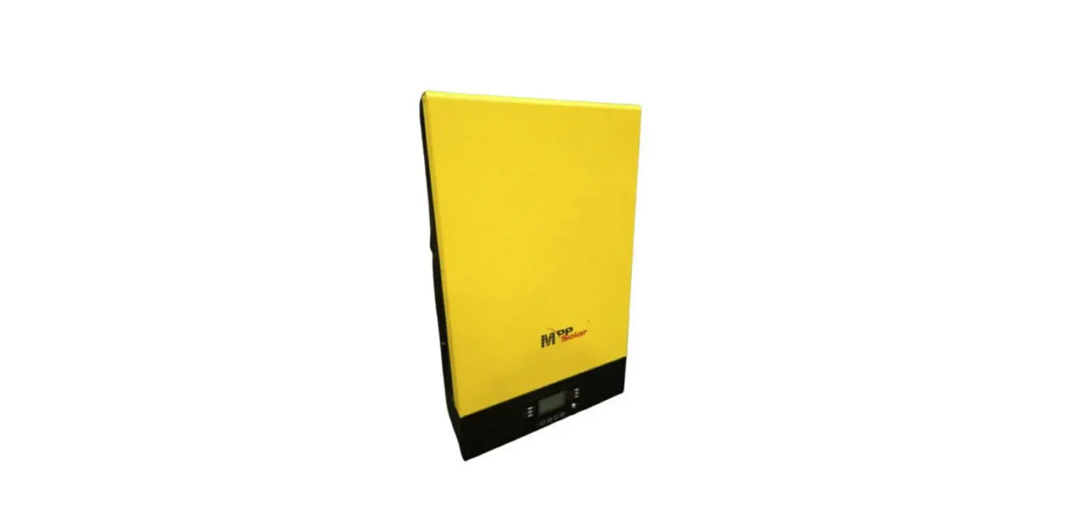
MPP Solar LVX6048 Axpert Charger/Inverter

General information
Getting start
This manual is used as a checking and repairing guide for INVERTER VII LV 6KW model. Before read this manual, it’s better to have some electrical or electronic background knowledge. With this guide, you can fix the inverter by yourself first.
There are five main parts of this guide:
- General information: This part is the basic information of the inverter; you can start to know the inverter from this chapter.
- Troubleshooting: This part will tell you what to do when you face a problem.
- Checking and measuring guide: This part will teach you how to check or repair the inverter by measuring the critical components.
- Assembling guide: This part teaches you how to take the board outside and fix the new one.
- Cables connection: This part is a reference for cable connection.
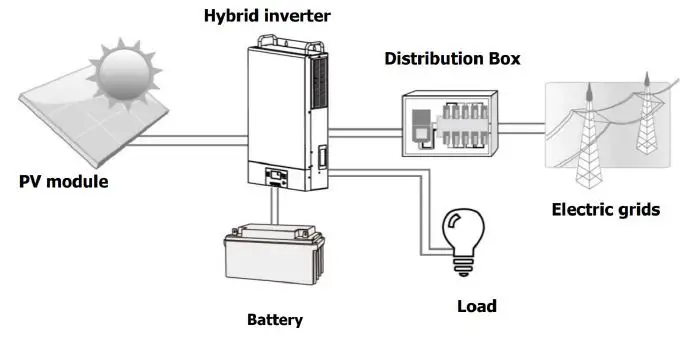
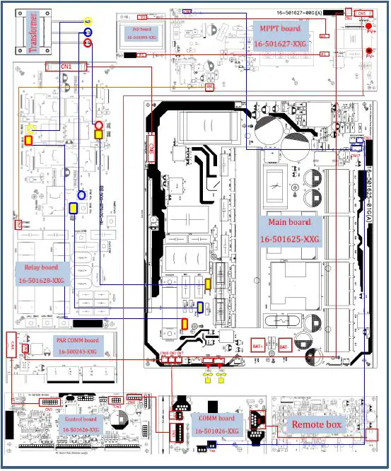
Basic topology introduction
The topology of the inverter shows as below:
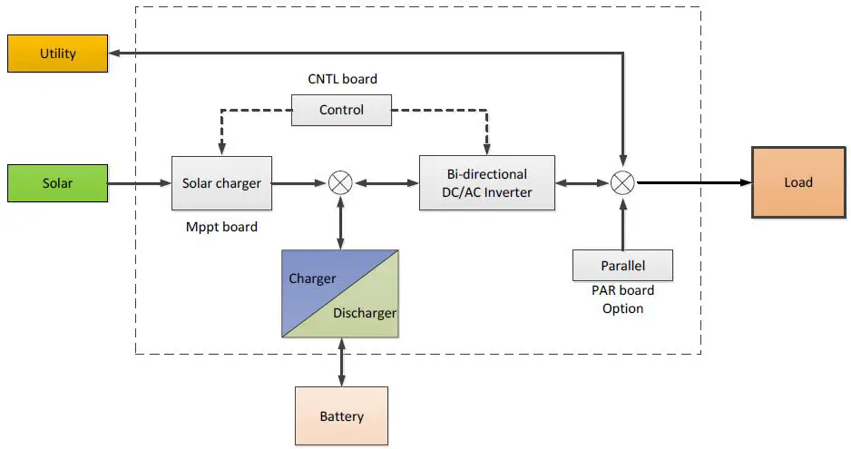
Compare with UPS or normal inverter, INVERTER combines a solar charger inside. Solar charger can be a supplement for battery when there is not grid or for saving energy purpose. And with the solar charger, the inverter can have more working modes than UPS. For detail information please refer to our user manual.
Overview the inverter
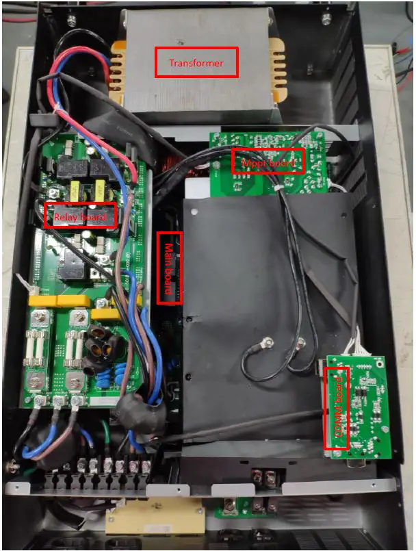
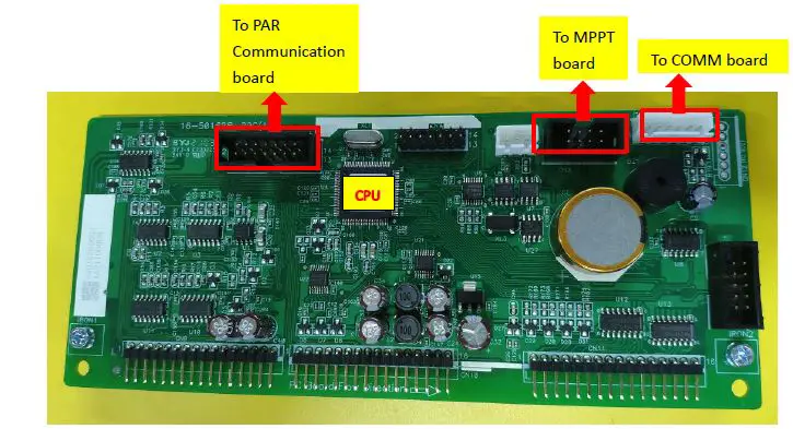
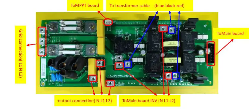
PCB Overview
Mainboard:
Control board:
MPPT board:
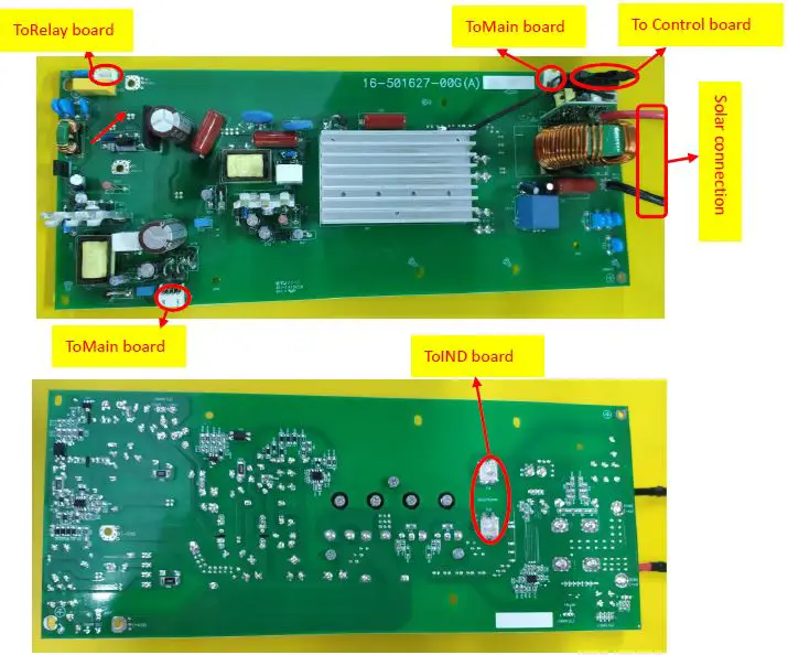
Relay board:
Troubleshooting
How to do
When the inverter was faulty, normally there are two main symptoms:
- No display at all;
- Fault code or warning code on the LCD;
When the fault occurred, please help to record the fault information and follow “How to check” of part 2.3 to check the inverter, then feedback the checking result to the service center. It will be very helpful for solving the problem as soon as possible.
Check the fault information
Please follow the steps as below to find the issues!
Make sure that you can finish all the steps and feedback us the results. Or we may not be able to give you the right solution.
- Step 1: Test the battery working mode.
Before turning on the inverter, only connect the battery with the inverter which means no solar input and grid input. Turn on the switch, the LCD will light up and wait for the battery connecting to load. If the connection is failed, please record the fault code. - Step 2: Test the grid bypass mode.
Before turning on the inverter, only connect the utility with the inverter. Without press any buttons, the LCD will light up. And wait for the utility connecting to load.
If the connection is failed, please record the fault code. - Step 3: Test the solar mode.
Before turning on the inverter, only connect the solar with the inverter. Without press any buttons, the LCD will light up. And wait for the solar connecting to load.
If the connection is failed, please record the fault code.
Fault condition
Note:
- When open the top cover, please have a look first, are there any obviously damaged parts?
- When take the main board out, please have a look around, are there any obviously damaged parts?
Not working at all/ No display
| Description | The inverter couldn’t startup completely. |
| Possible reason | 1. SPS module damaged. |
| How to check | 1. Firstly, please measure the resistor between BAT+ and BAT-. If it is not shorted, only connect the inverter with battery, and press “ON” button, could the inverter startup? If not, please check the fan. 2. If the LCD couldn’t light up and fan doesn’t work, please disconnect all the wires and open the top cover, and then take the main board outside by following part 4. |
| How to solve | Replace the main board. |
09 fault
| Description | Bus soft start fails. |
| Possible reason | DC-DC module was damaged. |
| How to check | Check the main board by following “3.1~3.4”; |
| How to solve | Repair the main board or replace it directly. |
56 fault
| Description | Battery couldn’t be detected. |
| Possible reason | Wire connection or fuse was burnt. |
| How to check | 1. Check the wire connection, the priority of the battery cable; 2. Check the main board by following “3.1”. |
| How to solve | Repair the main board or replace it directly. |
Test step
After replacing all defected components, testing steps can be used to confirm the repair result and the reliability of the Inverter.
Set up the testing system as below:
Checking and measuring guide
Check the battery side components
Fuse and capacitors
F3
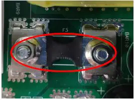
| Parts | Attribute | Reference values | Failure status |
| F3 | Resistor | 0 ohm | Open |
C11/C9/C13/C8/C12
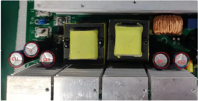
If the capacitors explode as below, they need to be replaced. 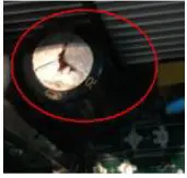
Power devices
DC/DC MOSFET: Q19/Q13/Q18/Q23 & Q24/Q11/Q17/Q20 & Q36/Q21/Q22/Q12 & Q40/Q26/Q25/Q14.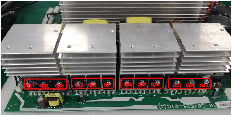
| Parts | Attribute | Reference values | Failure status |
| All: | Resistor1 | GS: 13.3K | Short or explosion |
| GD: 540K | |||
| DS: 0.58M | |||
| Diode | SD: 0.37V | ||
| DS: OL | |||
| Note1: When you use the multimeter to measure the resistor of the transistor, because of the capacitor in the circuit, it will cause the changing of the values when you measure the DS and GD. So we recommend you measure the diode forward voltage of SD, and the resistor of GS. These two values can reflect the situation of the transistor more correctly. Note: If one or more of them were damaged, please replace all of them. | |||
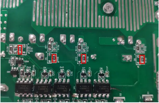
Drivers (This part is only used for repair checking)
Note:
Drivers usually need to be checked when users want to repair the boards. Because when power devices were damaged, the high voltage will rush to the driver circuit through the gates of power devices.
The reference of the resistors list as below:
- R46/R49/R52/R70/ R59/R41
- R56/R87/R88/R54/R75/R79

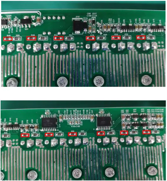
Use a multimeter to measure each resistor, find the burnt resistors and replace them; don’t need to replace them all.
| Parts | Attribute | Reference values | Failure status |
| All: 22ohm | Resistor | 22 ohm | Open or other values |
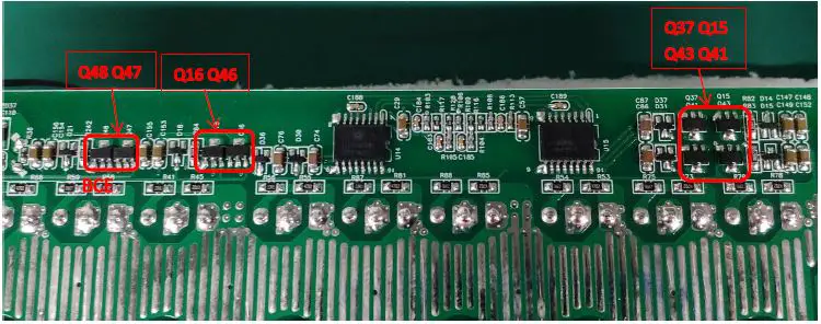
- The Q47 and Q 4 6 are 11 400011 00G (TR 2A 50V NPN SOT 89)
- The Q48 and Q 16 are 11 400010 00G (TR 3A 50V PNP SOT 89)
- The Q37 and Q 41 are 11 400011 00G (TR 2A 50V NPN SOT 89)
- The Q15 and Q 43 are 11 400010 00G (TR 3A 50V PNP SOT 89)
| Parts | Attribute | Reference values | Failure status |
| Q47/Q46/Q37/Q41 | Resistor | BE: 125K | Short or explosion |
| BC: 100K | |||
| CE: OL | |||
| Diode | BE: 0.55V | ||
| BC: 0.49V | |||
| CE: 2.8V | |||
| Q48/Q16/Q15/Q43 | Resistor | BE: 134k | Short or explosion |
| BC: 310K | |||
| CE: 15.7k | |||
| Diode | BE: 0.55V | ||
| BC: 1.96L | |||
| CE: 0.29V |
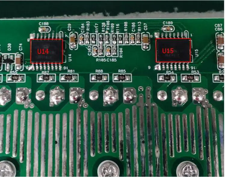
| Parts | Attribute | Reference values | Failure status |
| U14/U15 | Resistor | Pin14TOPin16: 3.2k Pin9TOPin11: 3.2k | Short or explosion |
| Note: If you are not sure about these components, we recommend you replacing them all. | |||
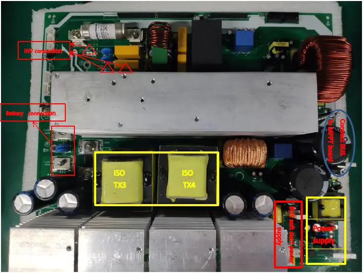
Check the bus side components
Power devices
DC/DC IGBT: Q30/Q29/Q27/Q28.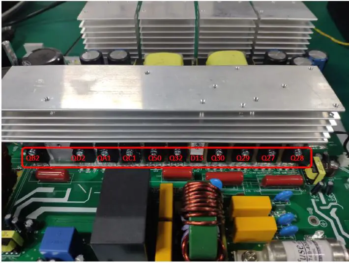
| Parts | Attribute | Reference values | Failure status |
| Q27/Q28/Q29/Q30 | Resistor1 | GE: 22.2 K | Short or explosion |
| GC: 215.5K | |||
| CE:400-500K | |||
| Diode | EC: 0.36V | ||
| CE: OL | |||
| Note1: When you use the multimeter to measure the resistor of the transistor, because of the capacitor in the circuit, it will cause the changing of the values when you measure the CE and GE. So we recommend you measure the diode forward voltage of EC, and the resistor of GE. These two values can reflect the situation of the transistor more correctly. Note: If one or more of them were damaged, please replace all of them. | |||
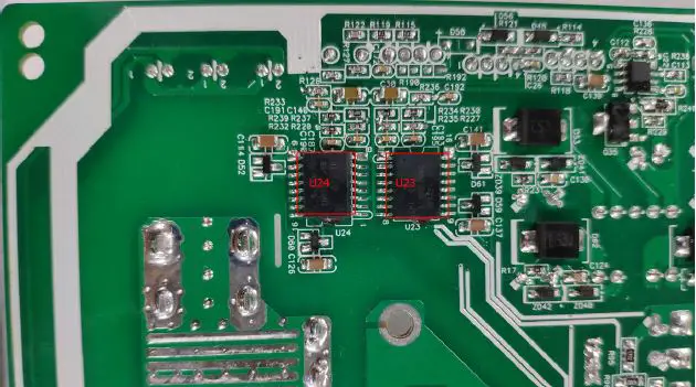
| Parts | Attribute | Reference values | Failure status |
| U23/U24 | Resistor | Pin14TOPin16: 3.4k Pin9TOPin11: 141k | Short or explosion |
| Note: If you are not sure about these components, we recommend you replacing them all. | |||
Drivers (This part is only used for repair checking)
Meanwhile, we also need to check the driver tubes of these power tubes.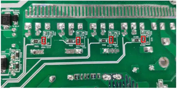
| Parts | Attribute | Reference values | Failure status |
| R96/R91/R101/R102 | Resistor | 47 ohm | Open or other values |
| Note2: When test the diode; please remove the R90/R99/R94/R97 from the board, or the test result is not right. | |||
Check the buck circuit Power devices
BUCK MOSFET and Diode: Q50 / Q32 / D13 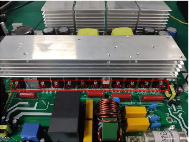
| Parts | Attribute | Reference values | Failure status |
| Q50 / Q32 | Resistor | GE: 23.5 K | Short or explosion |
| GC: 193K | |||
| CE: 400-500K | |||
| Diode | SD or CE: 0.36V | ||
| DS or EC: OL | |||
| D13 | Resistor | + to -: 185K | |
| – to +: OL | |||
| Diode | + to -: 0.38V | ||
| – to +: OL |
Drivers (This part is only used for repair checking) 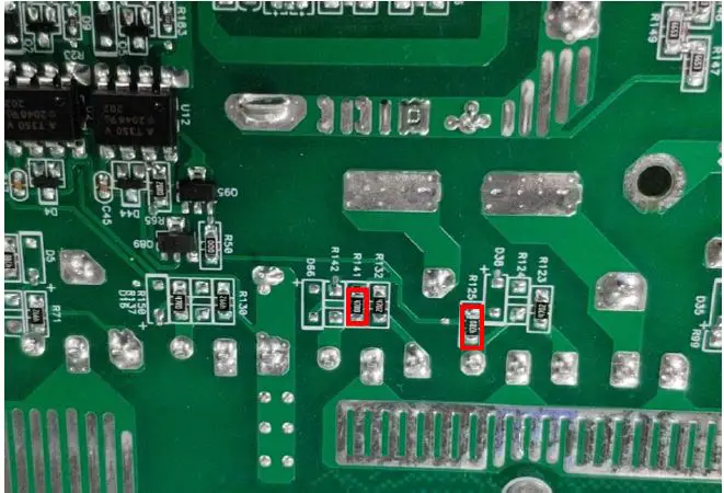
| Parts | Attribute | Reference values | Failure status |
| R125 / R141 | Resistor | 47 ohm | Open or other values |
| Note: When test the diode; please remove the R124/R142 from the board, otherwise the test result is not right. | |||
Check the INV full bridge
Power devices
INV IGBT: QB2/QD2/QA1/QC1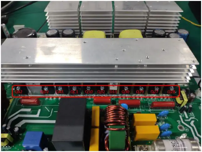
| Parts | Attribute | Reference values | Failure status |
| QB2/QD2/QA1/QC1 | Resistor | GE: 22.5K | Short or explosion |
| GC: 227k | |||
| CE: 10.5M | |||
| Diode | EC: 0.37V | ||
| CE: OL |
Note 1: If one or more of them were damaged, please replace all of them.
Drivers
| Parts | Attribute | Reference values | Failure status |
| R137/R48/R140/R144 | Resistor | 47 ohm | Open or other values |
Optocoupler: U12/U2/U4/U1/U3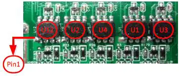
| Parts | Attribute | Reference values | Failure status |
| U1/U2/U3/U4/U12 | Resistor | PIN8 TO PIN5: 0.976M PIN7 TO PIN5: 0.976M | Short or explosion |
Check the MPPT board
Power devices
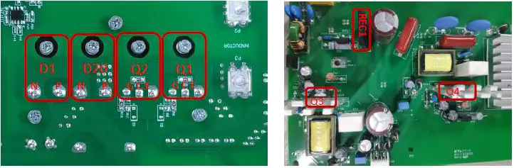
| Parts | Attribute | Reference values | Failure status |
| Q1, Q2, | Resistor | GE: 25k GC: 210K CE: OL | Short or explosion |
| Diode | EC: 0.381V CE: OL | ||
| D1、D20 | Resistor | P to N: 202.8k N to P: OL | Short or explosion |
| Diode | P to N: 0.38V N to P: OL | ||
| REC1 | Resistor | + to -: 406k – to +: 278K | Short or explosion |
| Diode | + to -: OL – to +: 0.5V | ||
| Q4、Q3 | Resistor | GS: 30K-50K GD: 300K-400K DS: OL | Short or explosion |
| Diode | SD: 0.511V DS: OL |
Disassembling guide
Open the case
| Remove screws on the top cover | 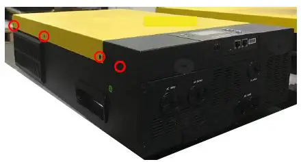 |
| Remove the remote control box on the top cover and then remove the top cover | 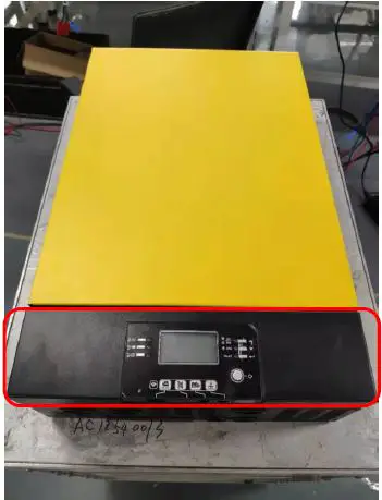 |
Remove the COMM board
| Remove the screws and three cables of the COMM board, and then remove the iron parts | 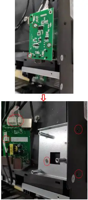 |
Remove the Relay board
| Remove the cables on the relay board. | 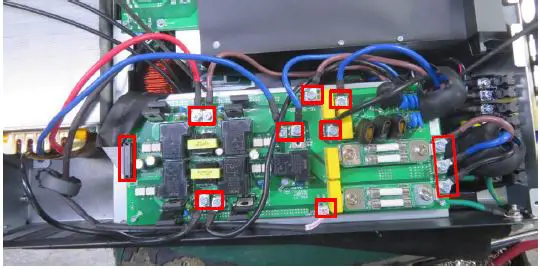 |
| Remove the fixing screws. | 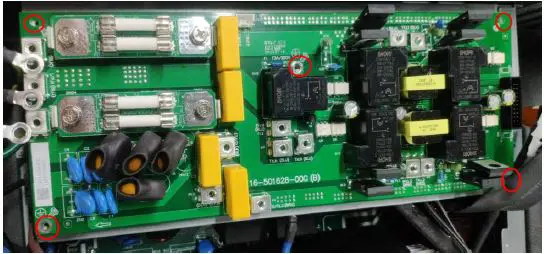 |
| Remove the supporting iron | 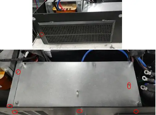 |
Remove the control board
| Remove the cables on the control board. | 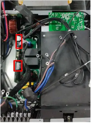 |
| Remove the fixing screws. | 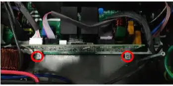 |
| Take out the control board. |
Note:
When you put the new control board on the main board, please make sure that the connection is correct and tightened. Don’t forget to put the screws and cables back.
Remove the fan paper and the MPPT board.
| 1. Take the plastic screws out. 2. Take two nuts out. 3. Take six screws out. 4. you can take the fan paper off. | 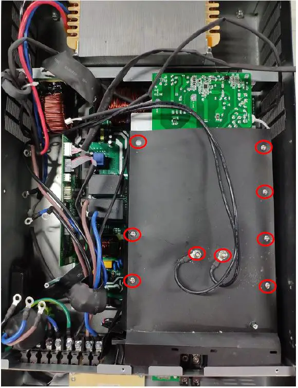 |
| Remove the screws and the signal cables of the MPPT board , and you can take the MPPT board paper off. | 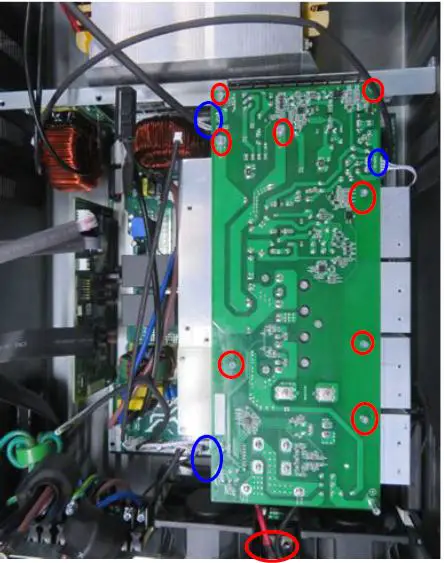 |
Remove the main board.
Note:
Before replacing the main board, please follow 4.2 ~ 4.4, and remove the control board, MPPT board, and fans first.
| Remove the power cables of Inverter output. Black cable is line 1;brown cable is line 2; blue cable is neutral. Do not make the wrong polarity. | 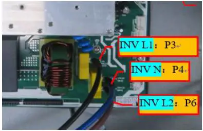 |
| Remove the fans cables. | 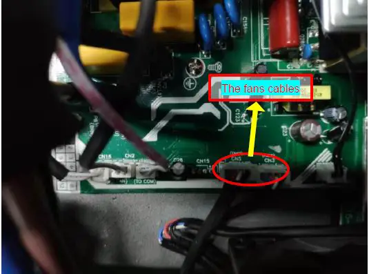 |
| Remove the screws and the signal cables on the main board. And then you can take the main board out. Note: There are ten screws to fix the main board. | 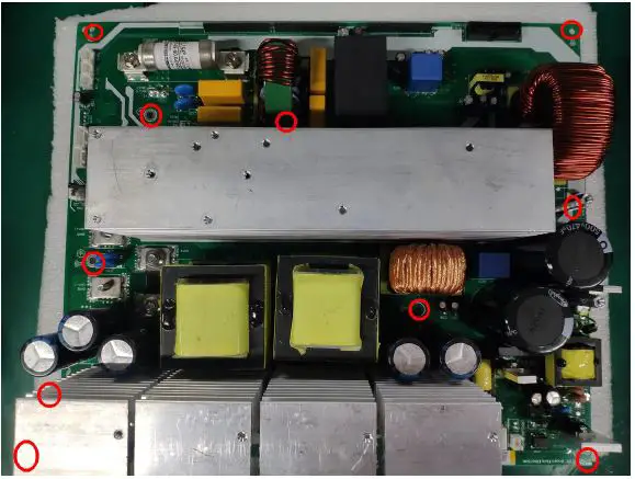 |
Cables connection
MPPT Model


 Solar Mppt Charge Controller User Manual")


