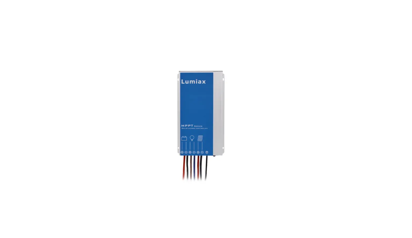
Lumiax SMR-MPPT2075 Solar Charge Controller MPPT
Product Information
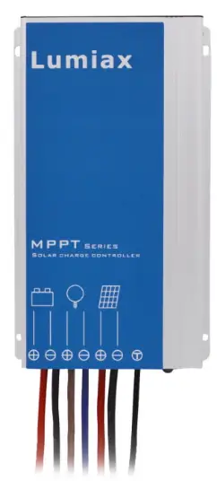
Product Name: Smart-MPPT series MPPT Solar charge controller
Model Number: 1.03.02.10048-1
Product Features:
- Programmable and waterproof
- High charging efficiency compared to traditional PWM controllers
- Suitable for a wide range of solar systems
- Comes with outstanding features
Safety Instructions and Liability Waiver:
- Only use the solar charge controller in PV systems according to the user manual and with solar panels specifications that meet the requirements of the controller.
- Avoid short-circuiting batteries and connect an in-line fuse or circuit-breaker on the + wire between the battery and controller, no more than 15cm from the battery terminal.
- Install batteries in a well-ventilated area to avoid flammable gases.
- Avoid touching or short-circuiting wires or terminals. Use isolated tools and work in a dry environment.
- Keep children away from batteries and the charge controller.
- The manufacturer is not liable for damages caused by improper use, neglecting battery manufacturer’s recommendations, unauthorized service or repair, unusual use, incorrect setup, or bad system design.
Product Usage Instructions
Installation:
- Connect the load first with corresponding red (positive) and black (negative) cables, then seal them with tape.
- Connect the battery with corresponding positive and negative cables. The load will be turned on.
- Connect the solar panel with the corresponding red (positive) and black (negative) cables. The controller will start charging.
- Confirm the LED display status. Refer to the “Faults and Alarms” section in the user manual to identify any issues.
- Ensure that the wire length between the battery and controller is as short as possible.
- Recommended Wire size:
Dear Clients,
Thanks for selecting the Smart-MPPT series solar controller. Please take the time to familiarise yourself with this user manual, as it will help you take full advantage of the controller’s features. This manual gives important recommendations for installing, using, and programming the solar controller. Read this manual in full before installing or connecting the solar controller.
Functions
Smart-MPPT series intelligent MPPT solar controller is programmable , waterproof and well-suited for a wide range of solar systems. The charging efficiency of this controller is higher than a traditional PWM controller, helping to get the most out of the solar panel.
It comes with a number of outstanding features, such as:
- Innovative Maximum Power Point Tracking(MPPT)
- technology, tracking efficiency >99.9%
- High charge conversion efficiency up to 97.5%
- Adjustable 5-stage timer for load ouput
- Monitoring of the running status and parameters
- Suitable for Gel, Liquid, AGM and Lithium battery
- Four stage charging: MPPT, boost, equalization, float
- 0℃ Charging Protection(Lithium)
- When BMS power off because of LVD, it can activate the system automatically
- Day/Night threshold can adjust automatically
- Configurable with an LCD remote programmer (S-Unit)
- Waterproof IP67, Strong and durable aluminum case
- Full automatic electronic protect function
Safty Instructions and Liability Waiver
Safety
- The solar charge controller may only be used in PV systems in accordance with this user manual and with solar panels specifications in line with the requirements of this controller. No energy source other than solar panels may be connected to the solar charge controller.
- Batteries store a large amount of energy, never shortcircuit a battery under any circumstances. We strongly recommend connecting an in-line fuse or circuit-breaker on the “+” wire between the battery and controller, nomore than 15cm from the battery terminal.
- Batteries can produce flammable gases. Avoid sparks and flames near the batteries. Make sure the battery is installed in a well ventilated area.
- Avoid touching or short circuiting wires or terminals. Be aware that the voltages on special terminals or wires can be several times greater than the battery voltage. Useisolated tools and only perform any work in a dry environment.
- Keep children away from batteries and the charge controller.
Liability Exclusion
The manufacturer shall not be liable for damages to the controller or battery caused by use other than as instructed in this manual, or if the battery manufacturer’s recommendations are neglected. The manufacturer shall
not be liable if there has been service or repair carried out by any unauthorised person, unusual use, incorrect setup, or bad system design.
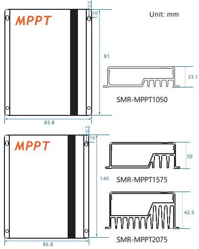
Dimensions(Unit: mm)
Installation
The following diagram provides an overview of the terminals. Please make sure to follow the proper order of connection.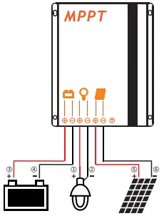
- As the chart, Connect the load first with corresponding red(positive) and black (negative) cables, then seal them with tape.
- Connect the battery with corresponding positive and negative cables, load will be on.
- Connect panel with the corresponding red(positive) and black( negative) cables, the controller begins charging.
- Confirm the LED display status, please refer to the 9.2 Faults and Alarms to identify the reason.
Make sure the wire length between battery and controller is as short as possible. Recommended Wire size:
- 10A: 2.5mm²
- 15/20A: 4mm².
Remote control, Default settings
Settings can be changed using the “S-Unit” infrared remote programmer. For detailed instructions and settings, please see the S-Unit programmer remote manual.
Be sure to only set one controller at a time.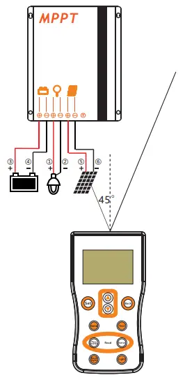
Reading the parameters
Press the “Parameter” key of the S-Unit to read the setting parameters of the controller.
| Num | Name | Factory Default |
| 1 | Time1 | 24H |
| 2 | Dim1 | 100% |
| 3 | Time2 | 0H |
| 4 | Dim2 | 100% |
| 5 | Time3 | 0H |
| 6 | Dim3 | 100% |
| 7 | Time4 | 0H |
| 8 | Dim4 | 0% |
| 9 | Time5 | 0H |
| 10 | Dim5 | 100% |
| 11 | D/N Thr | 5.0V |
| 12 | D/N Dly | 0min |
| 13 | Load I | 0.3A |
| 14 | Dim Auto | No |
| 15 | Battery | Gel |
| 16 | LVD | 11.2V |
| 17 | LVR | 12.0V |
- Dimming function, if you set 0%, the load will be off, otherwise the load will be on.
- “Load I” and “Dim Auto” settings are for DC series controllers with built-in LED driver, and do not work in this type controller.
Reading the running status
Press the “Status” key of the S-Unit to read the running status of the controller. This will display the current mode of the controller and any measured values.
| Num | Name | Name describe Unit |
| Status: | Charge | |
| 1 | Batt V | Battery voltage V |
| 2 | Load I | Load current A |
| 3 | Load V | Load voltage V |
| 4 | PV V | PV voltage V |
| 5 | PV I | PV current A |
| 6 | Energy | Total generating capacity AH |
| 7 | OD Times | Over discharge times Times |
| 8 | FC Times | Fully charge times Times |
| 9 | Day1-HV | A day ago highest voltage V |
| 10 | Day1-LV | A day ago lowest voltage V |
| 11 | Day2-HV | Two days ago highest voltage V |
| 12 | Day2-LV | Two days ago lowest voltage V |
| 13 | Day3-HV | Three days ago highest voltage V |
| 14 | Day3-LV | Three days ago lowest voltage V |
Test function(Streetlight mode)
Press the “Test” key of S-Unit, the controller will turn on the load for 30s. During daytime, this can verify correct installation and help with troubleshooting.
- Default “24H” mode, the test key is invalid.
Starting up the controller
Self Test
As soon as the controller is powered, it starts a self test routine. After this, the LED display will change to normal operation.
System Voltage
The controller applies to Lithium, AGM, Liquid and Gel battery, the factory default setting is suitable for Gel battery. It is your responsibility to check and ensure that these settings are correct for your battery, otherwise they must be amended.
When the controller is set to Lithium battery, the charging target voltage and charging recovery voltage can be set according to customer requirements.
The controller adjusts itself automatically to 12V or 24V system voltage when it is set to Gel, Liquid or AGM battery. If the battery voltage on start-up is 0V-15V then the controller infers a 12V system. If the battery voltage is 20V-30V the controller infers a 24V system.If the battery voltage is not within the normal operating rang(ca.0 to 15V or ca.20 to 30V) at start-up, please refer to 9.2 Faults & Alarms.
5.3 0℃ Charging Protection(Lithium Battery)
“0℃ Chg” can be set to “Yes”, “Slow” or “No”. When the controller detects that the ambient temperature is higher than 0℃, the charging function is normal. when the ambient temperature is low than 0℃, if the “0℃ Chg” is set to “Yes”, the charging function is normal, else if the “0℃ Chg” is set to “slow”, the max charging current is 20% of the rated current, else if the “0℃ Chg” is set to “No”, the controller does not charge the battery.
Load Output Timer Modes
Smart-MPPT series controller has advanced day/night time control functions. The modes of lighting can be based on customer needs.
Standard(24H)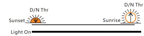
If “Time1” is set to “24H” and sent to the controller successfully, the controller’s load will always be on.
Dusk to Dawn (D2D)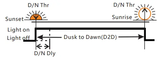
If “Time1” is set to “D2D”, the controller works in dusk to dawn mode.
- The dimming setting will still be active in this mode.
- If “Time1” is set to D2D mode, “Time4” cannot be set to T0T mode.
Five-stage Night Mode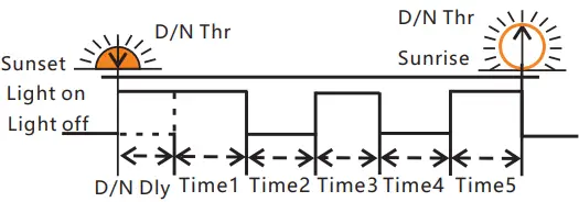
Time 1-5 and Dim 1-5 can be set individually to give variable load power throughout the night.
T0T mode(can set the load on time before dawn)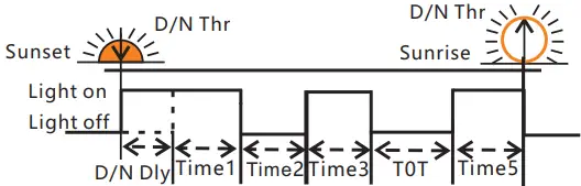
If “Time4” is set to “T0T”, this mode is T0T mode. If “Time4” is set to “T0T” then the controller will determine Time4 based on Time5 and previous data on the time of sunrise.
While “Time4” is set to T0T mode, “Time1” cannot set to D2D mode.
LVD, LVR, Threshold
Low Voltage Disconnect (LVD)
When the battery voltage drops below the LVD voltage, the controller will disconnect the load to prevent deep discharge of the battery. If this occurs, the battery should be well charged before resuming use.
Gel, Liquid and AGM Battery Battery capacity control
- SOC1:11.0~11.6V/22.0~23.2 V
- SOC2:11.1~11.7V/22.2~23.4 V
- SOC3:11.2~11.8V/22.4~23.6 V
- SOC4:11.4~11.9V/22.8~23.8 V
- SOC5:11.6~12.0V/23.2~24.0 V
Battery voltage control
LVD range: 10.8~11.8V/21.6~23.6V.
Lithium Battery
LVD range: 9.0~30.0V.
Low Voltage Reconnect (LVR)
If the low voltage disconnect is triggered, the controller will restore load connection only when the battery voltage increases above the LVR voltage.
- Gel, Liquid and AGM Battery
LVR range: 11.4~12.8V/22.4~25.6V. - Lithium Battery
LVR range:9.6~31.0V.
Day/Night Threshold, Day/Night Delay
The controller recognizes day and night based on the solar array open circuit voltage. This day/night threshold can be modified according to local light conditions and the solar array used.
Day/Night threshold setting range: 3.0~20.0V.
The actual time of turning on can be delayed by up to 30 minutes from the time the threshold was reached using the Day/Night delay setting (D/N Dly).
Day/Night delay time setting range: 0~30min.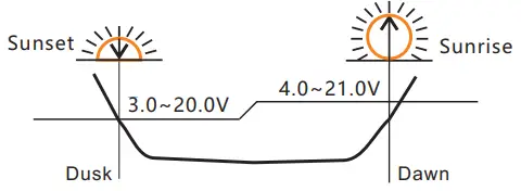
- Day/Night threshold voltage of load disconnect is 1V higher than the setting data, means the load will\ disconnect when the solar voltage at 4.0~21.0V.
- The controller will automatically adjust the day/threshold. If the lowest solar voltage is higher than the day/night threshold. The load will have no output the first night, then 24 hours later the controller will automatically adjust the setting to give output the following night.
LED indicators, Faults & Alarms
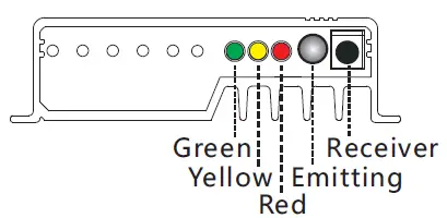
LED Display Explanation
| LED | Status | Function |
| Green LED | On | Not charged |
| Flash fast(0.1/0.1s) | MPPT charging | |
| Flash(0.5/0.5s) | Equal or Boost charging (Gel, Liquid or AGM) | |
| Flash slowly(0.5/2s) | Charging | |
| Yellow LED | Off | Over voltage protection |
| On | Battery is normal | |
| Slow flash(0.5/2s) | Battery voltage is low | |
| Fast flash(0.1/0.1s) | Low voltage protection | |
| Red LED | Off | Work normal |
| On | The output power is 0. | |
| Flash(0.5s/0.5s) | Over temperature | |
| Fast flash(0.1/0.1s) | Short circuit or over * current protection |
Detailed fault information can be read by S-Unit remote controller.
Faults & Alarms
| Fault | Status | Reason | Remedy |
|
Loads are not powered | Low volt. protection | Low Battery capacity | Recharge battery above LVR. |
| Overcurrent, short circuit protection | Overload or load short- circuit | Switch off all loads, remove short-circuit, load will be reconnected after 1 minute. | |
| Over temp. protection | Controller temp. is too high | Controller will turn the system off until temperature is below 60 ° C. | |
| High voltage at battery terminal | Over voltage protection | Battery overvoltage >15.5V/31V (Li: CVT+0.2V) | Check if other sources overcharge the battery. If not,controller is damaged. |
| Battery wires or battery fuse damaged, battery has high resistance. | Check battery wires, fuse and battery. | ||
| Incorrect system voltage | All LED fast flashing | Battery voltage not in right range | Charge or discharge battery to correct the voltage |
| Battery is empty after a short time | Low voltage protection | Battery has low capacity | Change battery |
| Battery not charging | Green LED is on | PV panel fault or reverse connection | Check panels and wire connections |
Safety Features
| Solar terminal | Battery terminal | Load terminal | |
| Reverse polarity | Protected *2 | Protected | Protected *2 |
| Short circuit | Protected*1 | Protected *3 | Switches off immediately |
| Over current | Switches off with delay | ||
| Reverse Current | Protected | ||
| Over voltage | Max.55V *4 | Max. 35V *5 | |
| Under voltage | Switches off | ||
| Over temp. | The controller cuts off the load if the temperature reaches the set value. | ||
- When the PV doesn’t charge,the controller will not be damaged if short-circuit just happened in the PV array. Warning: It is forbidden to short-circuit the PV array during charging .Otherwise, the controller may be damaged.
- Controller can protect itself, but load might be damaged.
- Battery must be protected by fuse.
- Please refer to “11.Technical Data” to get the max voltage of PV panel.
- Please refer to “11.Technical Data” to get the max voltage of battery.
Warning:
- The combination of different error conditions may cause damage to the controller.
- Always remove the error before you continue connecting the controller.
Technical Data
| Item | SMR-MPPT1050 | SMR-MPPT1575 | SMR-MPPT2075 | ||
|
Battery Parame- ters | Max Charging Current | 10A | 15A | 20A | |
| System Voltage | 12V | 12V/24V automatical recognization | |||
| Max input power | 130W | 200W/400W | 260W/520W | ||
| Max volt on Bat. Terminal | 25V | 35V | |||
| Battery Type | Lithium, Liquid, Gel, AGM(Programmable, default: Gel) | ||||
|
Liquid, Gel, AGM | MPPT Charging Volt. | <14.5V@25℃ | <14.5/29V@25℃ | ||
| Boost Voltage | 14.5V @25℃ | 14.5/29V @25℃ | |||
| Equalization Volt. | 14.8V @25℃ | 14.8/29.6V @25℃(Liquid, AGM) | |||
| Float Voltage | 13.7V @25℃ | 13.7/27.4V @25℃ | |||
| Low Volt. Disconnect | 10.8~11.8V,SOC1~5 | 10.8~11.8V/21.6~23.6V; SOC1~5(Default: 11.2/22.4V) | |||
| Reconnect Voltage | 11.4~12.8V | 11.4~12.8V/22.8~25.6V(Default: 12.0/24.0V) | |||
| Overcharge Protect | 15.5V | 15.5/31.0V | |||
| Temp. Compensation | -4.17mV/K per cell (Boost, Equalization), -3.33mV/K per cell (Float) | ||||
|
Lithium | Charging Volt. target | 10.0~17.0V | 10.0~32.0V(Lithium, Programmable) | ||
| Charging Volt. recovery | 9.2~16.8V | 9.2~31.8V(Lithium, Programmable) | |||
| Low Volt. disconnect | 9.0~15.0V | 9.0~30.0V(Lithium, Programmable) | |||
| Low Volt. reconnect | 9.6~16.0V | 9.6~31.0V(Lithium, Programmable) | |||
| 0℃ Charge Protection | Yes, No, Slow(Default: Yes) | ||||
| Panel Parame- ters | Max volt on PV terminal | 45V | 55V *1 | ||
| Dusk/Dawn detect volt. | 3.0~8.0V | 3.0~20.0V(Programmable) | |||
| Day/Night delay time | 0~30Min(Programmable) | ||||
| MPPT tracking range | (Battery Voltage + 1.0V)~Voc*0.9 *2 | ||||
| Max tracking efficiency | >99.9% | ||||
| Load | Output Current | 10A | 15A | 20A | |
|
System Parame- ters | Max charge conversion | 96.5% | 97.5% | ||
| Self consumption | 6mA | ||||
| Dimensions | 85.8 * 81 *23.1mm | 85.8 * 145 * 30mm | 85.8 * 145 * 42.5mm | ||
| Weight | 260g | 600g | 720g | ||
| Ambient temperature | -35~+60℃ | ||||
| Ambient humidity | 0~100%RH | ||||
| Protection degree | IP67 | ||||
| Max Altitude | 4000m | ||||
- PV panel Voc can not exceed this value, otherwise it will damage the controller.
- Voc means the open circuit voltage of the solar panel.
User Manual_Smart-MPPT series_MA
CE, Rohs, ISO9001:2015
Subject to change without notice!


 Solar Mppt Charge Controller User Manual")


