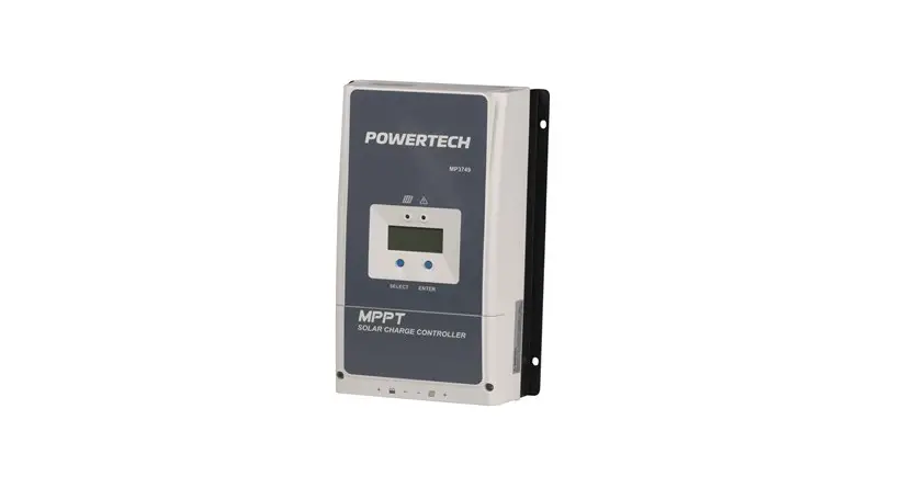
POWERTECH MP3749 MPPT Solar Charge Controller Instruction Manual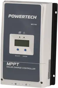
IMPORTANT SAFETY INSTRUCTIONS
Please reserve this manual for future review.
This manual contains all safety, installation, and operation instructions for the Tracer-AN series MPPT solar controller (“controller” referred to in this manual).
- Read all the instructions and warnings carefully in the manual before installation.
- No user-serviceable components inside the controller; please do not disassemble or attempt to repair the controller.
- Mount the controller indoors. Avoid exposure to the components and do not allow water to enter the controller.
- Install the controller in a well-ventilated place; the controller’s heat sink may become very hot during operation.
- It is suggested to install appropriate external fuses/breakers.
- Make sure to switch off all PV array connections and the battery fuse/ breakers before controller installation and adjustment.
- Power connections must remain tight to avoid excessive heating from a loose connection.
- The entire system should be installed by professional and technical personnel.
Explanation of Symbols
- To enable users to use the product efficiently and ensure personal and property safety, please read related literature accompanying the following symbols.
- Please read the literature accompanying the following symbols.
| Symbol | Definition |
| TIP | TIP: Indicates any practical advice for reference. |
 | IMPORTANT: Indicates a critical tip during the operation, if ignored, may cause the device to run in error. |
 | CAUTION: Indicates potential hazards, if not avoided, may cause the device damaged. |
 | WARNING: Indicates the danger of electric shock, if not avoided, would cause casualties. |
 | WARNING HOT SURFACE: Indicates the risk of high tem- perature, if not avoided, would cause scalds. |
 | Read the user manual carefully before any operation. |
QUICK START GUIDE
- For best results, use the thickest cable you can afford that will fit in the connectors.
- Make sure all screwed connections are as tight as possible.
- Panel (PV) voltage must be higher than battery voltage.
A 12V battery is OK with a 12V or higher solar (PV) array, a 24V battery will only work with a 24V or higher solar (PV) array. - Maximum open-circuit Panel (PV) array voltage is 100V
- Ensure battery line has an adequate fuse or circuit breaker.
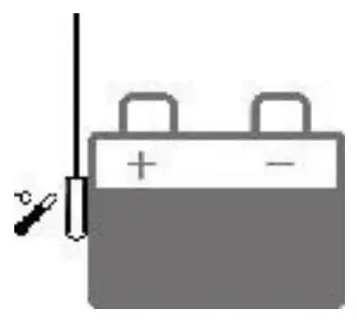
- Very Important: Connect battery to controller BEFORE solar panel, and check that the battery voltage is registering on the display. (Repeatedly press “select” button until you see “Batt Voltage”).
- Set your battery type before connecting the solar array to your regulator.
Full instructions for setting the battery type can be found on page 22.
A summary of common battery types can be found below.
SEL = Sealed Lead Acid (SLA, AGM)
GEL = Gel Battery
FLD = Flooded Cell (Lead acid with filler caps, car batteries etc)
LFP4S = 14.8V/12V Lithium Batteries
LPF8S = 29.8V/24V Lithium Batteries - Finally connect up the solar (PV) array and check that charging is actually taking place (in the battery menu).
GENERAL INFORMATION
OVERVIEW
Based on multiphase synchronous rectification technology(MSRT) and advanced MPPT control algorithm, adopt dual-core processor and conegative design, Tracer-AN series controllers own the fast response characteristics, high reliability, and industrial standards. MSRT guarantees a high conversion efficiency in any charging power, which sharply improves the solar system’s energy efficiency. The new optimized MPPT tracking technology can fast track the PV array’s max power point in any situation and obtains the maximum energy in real-time.
The automatic power reduction function fully ensures access to excess PV modules and high-temperature running.
The Tracer-AN series controller owns a self-adaptive three-stage charging mode based on a digital control circuit. This function can effectively prolong the battery’s lifespan and significantly improve the system’s performance.
The load/utility/generator dry contact to connect external devices conveniently composes a hybrid power system easily.
Comprehensive electronic protections, including overcharging, overdischarging, and PV reverse polarity protection, effectively ensure a more reliable and durable solar system operation for a longer running time.
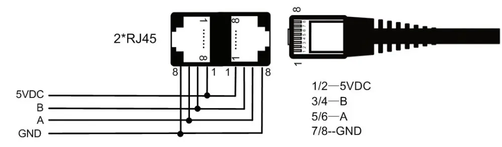
The isolated RS485 port with standard MODBUS communication protocol and 5V power supply is easy to expand the application. Up to 6 controllers connected in parallel are supported. The controller can be widely used for various applications, e.g., solar RV, household system and field monitoring, etc.
Features:
- Comply with IEC62109-1 and EN61000-6-1/3 standard certification
- High quality and low failure rate components of ST or IR to ensure the service life
- High tracking efficiency of MPPT no less than 99.5%.
- Maximum DC/DC transfer efficiency is as high as 98.6%*; full load efficiency is up to 98%*
- Accurate recognizing and tracking technology of multi-peaks maximum power point
- Wider MPP running voltage to increase the PV modules’ utilization ratio
- Support the lead-acid and lithium batteries
- Program temperature compensation for batteries.
- Real-time energy statistics function
- High temperature charging automatic power reduction function
- 100% charging and discharging in the working environment temperature range
- Up to 6 controllers connection in parallel to expand the system
- Load dry contact to control the external load switch
- To set the first and the second disconnection voltage of load by the software
- Auto-control of utility and generator dry contact design to compose a hybrid power system easily
- Remote temperature and voltage sensor design to collect more accurate battery temperature/terminal voltage and eliminate the battery cables’ voltage drop
- Isolated RS485 communication ports (Modbus protocol)
- 5V/200mA RS485 communication ports with short circuit protection
- Support remote monitoring and parameters setting via the APP or PC software
CHARACTERISTICS
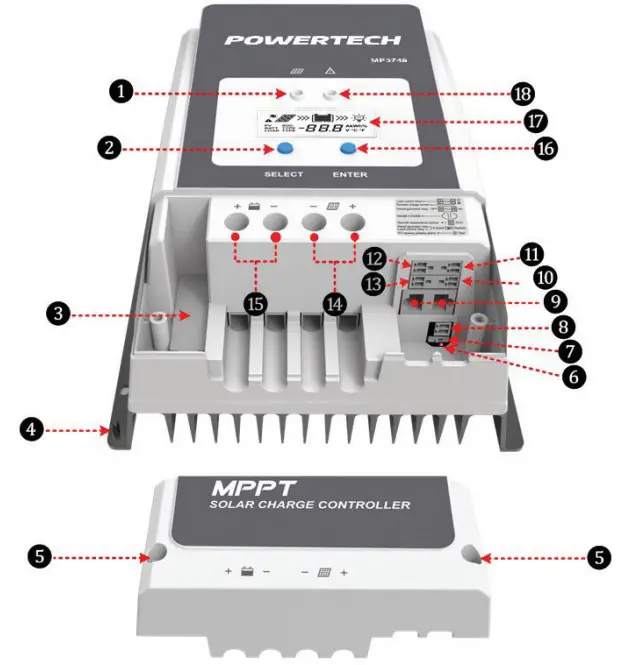
Figure 1 Product Characteristics
- Charging indicator
- SELECT button
- External fuse
- Grounding terminal
- Screw hole (M4)
- (PV reverse polarity) alarm indicator
- Generator/Load) dry contact enable switch1
- RTS interface2
- RS485 port (5VDC/200mA)3
- (Utility/Generator) dry contact ON interface
- RBVS interface4
- (Load) dry contact interface5
- (Utility/Generator) dry contact OFF interface
- PV terminals6
- Battery terminals6
- ENTER button
- LCD
- Fault indicator
- Set the (Generator/Load) dry contact enable switch to ON, the (Load) dry contact is enabled; while it is disabled when the switch is set to OFF.
- Connect an RTS (Remote Temperature Sensor) to remotely detect the battery temperature. The sampling distance is no longer than 20m.

CAUTION
Suppose the temperature sensor is a short circuit or damaged. In that case, the controller can charge or discharge the battery at the default temperature setting of 25°C (no temperature compensation). - When connecting the controller to external devices, only one of the RS485 ports can be used; when connecting multiple controllers in parallel, RS485 ports are for cascaded use.

- Connect an RBVS (Remote Battery Voltage Sensor) to detect accurate battery voltage. The sampling distance is no longer than 20m.
- Low Voltage Disconnect Voltage (VLVD) disconnects the dry contact.
Low Voltage Reconnect Voltage (VLVR) makes the dry contact connect. When the lithium battery and inverter are used together in the system, connect the controller’s (Load) dry contact to the inverter’s start-stop dry contact. The controller will manage the inverter’s start or stop. If the lithium battery fails, It can protect the controller from being damaged because of the over-current by preventing the controller from directly starting the inverter. - The controller is designed with a common negative polarity. The negative polarity of the PV and the battery is located on the same busbar.
NAMING RULES: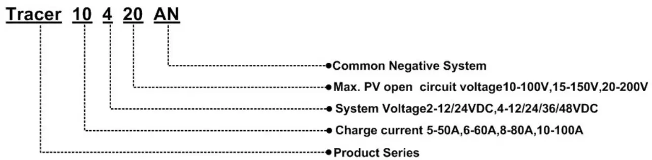
INSTALLATION
ATTENTION
- Be very careful when installing the batteries. Please wear eye protection when installing the open-type lead-acid battery and rinse with clean water in time for battery acid contact.
- Keep the battery away from any metal objects, which may cause a battery short circuit.
- Acid gas may be generated when the battery is charged. Ensure that the surrounding environment is well ventilated.
- Avoid direct sunlight and rain infiltration when installing it outdoor.
- Loose power connections and corroded wires may result in high heat that can melt wire insulation, burn surrounding materials, or even cause a fire. Ensure tight connections and secure cables with clamps to prevent them from swaying while moving the inverter.
- Only charge the lead-acid and lithium-ion batteries within the control range of this controller.
- The battery connector may be wired to another battery or a bank of batteries. The following instructions refer to a singular battery. Still, it is implied that the battery connection can be made to either one battery or a group of batteries in a battery bank.
- Select the system cables according to 5A/mm2 or less current density.
REQUIREMENTS FOR THE PV ARRAY
Serial connection (string) of PV modules
As the core component of the solar system, the controller needs to suit various PV modules and maximize solar energy conversion into electricity.
According to the open-circuit voltage (VOC) and the maximum power point voltage (VMPP) of the MPPT controller, the serial connection of PV modules suitable for different controllers can be calculated. The below table is for reference only
| System voltage | 36cell Voc < 23V | 48cell Voc < 31V | 54cell Voc < 34V | 60cell Voc < 38V | ||||
| Max. | Best | Max. | Best | Max. | Best | Max. | Best | |
| 12V | 4 | 2 | 2 | 1 | 2 | 1 | 2 | 1 |
| 24V | 4 | 3 | 2 | 2 | 2 | 2 | 2 | 2 |
| System voltage | 72cell Voc < 46V | 96cell Voc < 62V | Thin-Film module Voc > 80V | ||
| Max. | Best | Max. | Best | ||
| 12V | 2 | 1 | 1 | 1 | 1 |
| 24V | 2 | 1 | 1 | 1 | 1 |
IMPORTANT
The above parameters are calculated under standard test conditions (STC (Standard Test Condition): Module Temperature 25°C, Air Mass 1.5, Irradiance 1000W/m2.)
Max. PV Array Power
This MPPT controller has the function of charging current/power-limiting.
During the charging process, when the actual charging current or charging power exceeds the rated charging current or charging power, the controller automatically limits the current or power. It charges the battery as per the rated charging current or charging power. This function can effectively protect the controller’s charging modules and prevent damage to the controller due to the over-connected PV array. The actual running status of the PV array is as follows:
Condition 1: Actual PV array’s charging power ≤ Rated controller’s charging power
Condition 2: Actual PV array’s charging current ≤ Rated controller’s charging current
When the controller works under “Condition 1” or “Condition 2,” it charges the battery as per the actual charging current or actual charging power. At this time, the controller can work at the maximum power point of the PV array
WARNING
When the PV module’s power is not greater than the rated charging power, the PV array’s maximum open-circuit voltage is more than 100V at the lowest temperature, the controller is damaged.
Condition 3: Actual PV array’s charging power >Rated controller’s charging power
Condition 4: Actual PV array’s charging current >Rated controller’s charging current
When the controller operates under “Condition 3” or “Condition 4,” it will carry out the charging as per the rated current or power.
WARNING
When the PV module’s power is greater than the rated charging power, the PV array’s maximum open-circuit voltage is more than 100V at the lowest temperature), the controller is damaged.
According to the “Peak Sun Hours diagram,” if the PV array’s power exceeds the controller’s rated charging power, the charging time as per the rated power is prolonged. The controller can obtain more energy. However, in the practical application, the PV array’s maximum power shall be not higher than 1.5 times the controller’s rated charging power. Suppose the PV array’s maximum power exceeds the controller’s rated charging power too much.
In that case, it may cause the PV array’s waste and increase the PV array’s open-circuit voltage due to the environmental temperature. It may increase the damage probability to the controller. For the recommended maximum power of the PV array, please refer to the table below:
| Model | Rated charge current | Rated charge power | Max. PV power | Max. PV open circuit voltage |
| MP3749 | 60A | 750W/12V1500W/24V | 1125W/12V2250W/24V | 100V (lowest temperature) 92V (25°C) |
WIRE SIZE
The wiring and installation methods must conform to the national and local electrical code requirements.
PV wire size
The PV array’s output current varies with its size, connection method, and sunlight angle. The minimum wire size can be calculated by its ISC(short circuit current). Please refer to the ISC value in the PV module’s specifications. When the PV modules are connected in series, the total ISC is equal to any PV module’s ISC. When the PV modules are connected in parallel, the total ISC is equal to the sum of all the PV module’s ISC. The PV array’s ISC must not exceed the controller’s maximum PV input current.
For max. PV input current and max. PV wire size, please refer to the table as below:
| Model | Max. PV input current | Max. PV wire size |
| MP3749 | 60A | 16mm2/6AWG |
![]()
CAUTION
When the PV modules are connected in series, the total voltage must not exceed the max. PV open circuit voltage at 25 environment temperature.
Battery wire size
The battery wire size must conform to the rated current, the reference size as below:
| Model | Max. PV input current | Max. PV wire size |
| MP3749 | 60A | 16mm2/6AWG |
![]()
CAUTION
- The wire size is only for reference. Suppose a long-distance exists between the PV array and the controller or between the controller and the battery. In that case, larger wires shall be used to reduce the voltage drop and improve the system performance.
- The recommended wire for the battery is that its terminals are not connected to any additional inverter.
DRY CONTACT INSTRUCTION
Dry contact parameter
Rated Value: 5A/30VDC
Maximum Value: 0.5A/60VDC
Control the utility/generator ON/OFF via the (Utility/Generator) dry contact
Utility/Generator start-up Voltage (VON) = Under Voltage Warning Voltage Utility/Generator stop Voltage (VOFF) = Under Voltage Warning Recover Voltage Battery Voltage (VBAT)
- Start-up the Utility/Generator: VBAT < VON.
- Stop the Utility/Generator: VBAT > VOFF.
![]()
CAUTION
- Before start or stop the Utility/Generator via the (Utility/ Generator) dry contact, you shall set the switch to the ON position.
- The VON and VOFF can be set via the PC software. The Battery Control Voltage Parameters refer to Operation – Settings
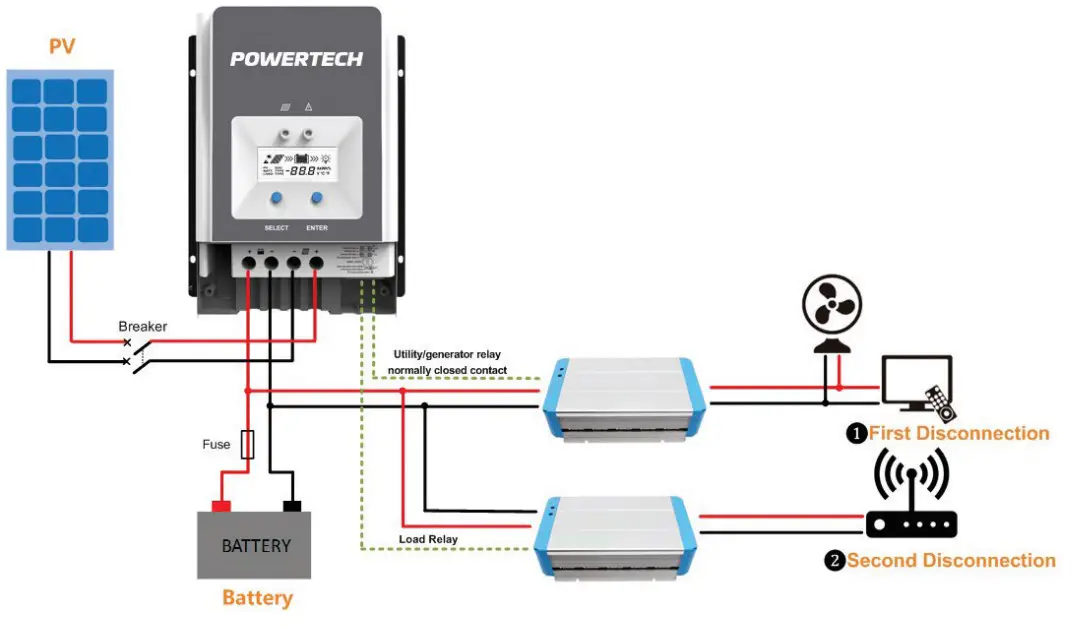
Control the load first disconnection and second disconnection.
Battery Voltage (VBAT)
Under Voltage Warning Voltage (VUVW)
Under Voltage Warning Recover Voltage (VUVWR)
Low Voltage Disconnect Voltage (VLVD)
Low Voltage Reconnect Voltage (VLVR
- (Utility/Generator) dry contact OFF interface
VBAT ≤ VUVW: The (Utility/Generator) dry contact OFF interface controls
the load ❶ first disconnection.
VBAT ≥ VUVWR: (Utility/Generator) dry contact OFF interface controls the load ❶ first connection. - + (Load) dry contact
VBAT ≤ VLVD: The (Load) dry contact controls the load ❷ second disconnection.
VBAT ≤ VLVR: The (Load) dry contact controls the load ❷ second connection.
![]()
CAUTION
The Battery Control Voltage Parameters refer to Operation – Settings.
WARNING
When the system is power off, the (Utility/Generator) dry contact OFF interface is closed. Please check the system in time.
Refer to below the diagram:
MOUNTING
WARNING
- Risk of explosion! Never install the controller in a sealed enclose with flooded batteries! Do not install the controller in a confined area where battery gas can accumulate.
- Risk of electric shock! When wiring the solar modules, the PV array can produce a high open-circuit voltage, so turn off the breaker before wiring and be careful when wiring.
- Controllers have no battery reverse protection. Do not reverse the battery during the wiring. Otherwise, the controller may be damaged.
![]()
CAUTION
The controller requires at least 150mm of clearance above and below for proper airflow. Ventilation is highly recommended if mounted in an enclosure.
Installation procedures:
Step 1: Determine the installation location and heat-dissipation space
When installing the controller, ensure enough air flowing through the controller’s heat sink. Please leave at least 150mm clearance away from the upper and lower edges.
![]()
CAUTION
Ventilation is highly recommended if mounted in an enclosure.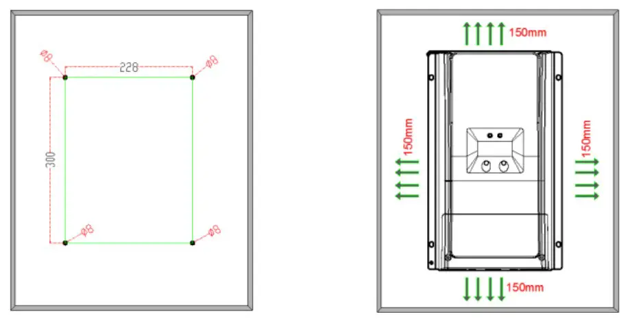
Step 2: Remove the terminal protective cover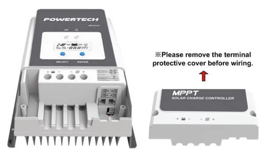
Step 3: Connect the battery❶ (Left) and PV❷ (Right)
IMPORTANT
Disconnect the system in reverse order.
WARNING
Controllers have no battery reverse protection. Do not reverse the battery during the wiring. Otherwise, the controller may be damaged.
![]()
CAUTION
- During the wiring, please do not close the circuit breaker or fuse. Ensure that the leads of “+” and “-” poles are polarity correctly.
- A fuse whose current is 1.25 to 2 times the controller’s rated current must be installed on the battery side with a distance from the battery no longer than 150 mm.
- Please connect the inverter directly to the battery, not to the controller’s load side.
- When the lithium battery and inverter are used together in the system, connect the controller’s (Load) dry contact to the inverter’s start-stop dry contact.
Single Controller: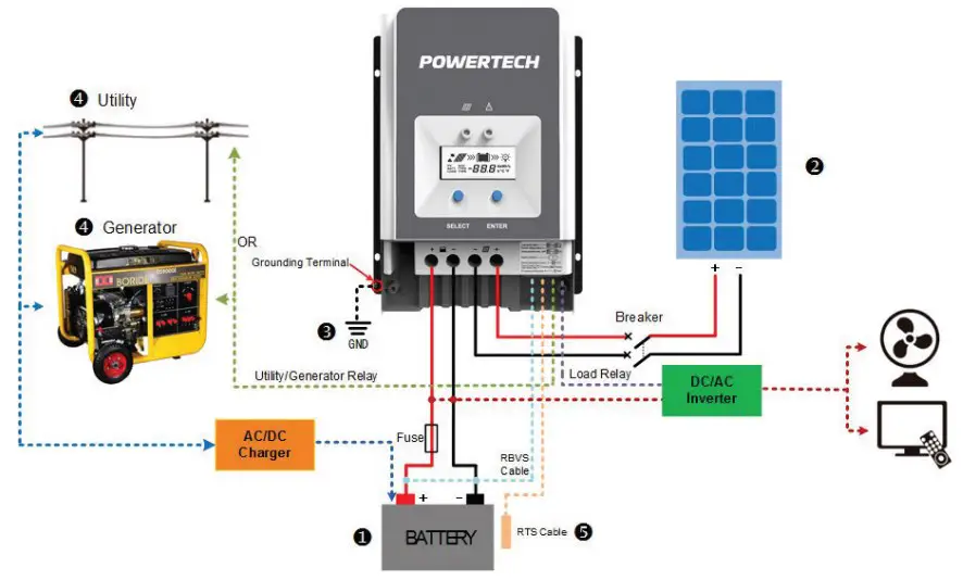
Connection in Parallel: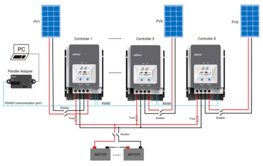
Step 4: Grounding
The MP3749 uses a common-negative controller. Negative terminals of the PV array, the battery can be grounded simultaneously, or any terminal is grounded. However, according to the practical application, the PV array’s negative terminals, battery, and load can also be ungrounded.
Simultaneously, the grounding terminal on the shell must be grounded, which effectively shields the electromagnetic interference from the outside and prevents some electric shock to the human body due to the electrification of the shell.
![]()
CAUTION
For common-negative systems, such as the RV system, it is recommended to use a common-negative controller. If a common-positive controller is used and the positive electrode is grounded in the common-negative system, the controller may be damaged.
Step 5: Connect Accessories
- Connect the remote temperature sensor cable
Connect the remote temperature sensor cable to the interface ❽ and place the other end close to the battery.
CAUTION
Suppose the remote temperature sensor is not connected to the controller. In that case, the controller can charge or discharge the battery at the default 25 °C(no temperature compensation). - Connect the remote battery voltage sensor cable
Connect the remote battery voltage sensor cable to the interface ⓫ and connect the other end to the battery terminals. - Connect the accessories for RS485 communication; refer to the accessories list.
Step 6: Power on the controller
Close the battery’s fuse to power on the controller. After the LCD normally displays, close the PV array’s circuit breaker. The charging indicator is slow flashing during the PV charging process.
![]()
CAUTION
If the controller can not work properly or the fault indicator shows an abnormality, please refer to the Troubleshooting Section.
OPERATION
INDICATOR
| Indicator | Colour | Status | Instruction |
 | Green | ON solid | PV connection is normal, but the voltage is low and not charging. |
| Green | OFF | No PV voltage(night time) or PV connection fault | |
| Green | Slowly flashing (1Hz) | PV is charging | |
| Green | Fast flashing(4Hz) | PV over voltage |
IMPORTANT
The fault indicator refers to LCD Display Section
BUTTONS
| Modes | Note |
| (Load) dry contact | In manual mode, short press the “ENTER” button to turn on/ off the (Load) dry contact. |
| Clear fault | Press the “ENTER” button |
| Browsing mode | Short press the “SELECT” button |
| Setting mode | Long-press the “ENTER” button to enter the Setting mode, and short press the “SELECT” button to modify the parameter. Then short press the “ENTER” button to confirm or exit the current interface automatically after more than 10S. |
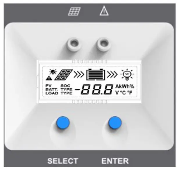
LCD DISPLAY
Status Description
| Name | Symbol | Status |
| PV array |  | Day |
 | Night | |
| No charge | ||
| Charging | ||
| PV | PV array’s voltage, current, and generate energy | |
| Battery |  | Battery capacity, In Charging |
| BATT | Battery Voltage, Current, Temperature | |
| BATT. TYPE | Battery Type | |
| Load |  | (Load) dry contact connected |
| (Load) dry contact disconnected |
Browse interface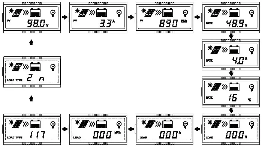
IMPORTANT
When no operation, the display interface will be an automatic cycle except for the load time1 and load time 2 interface.
LCD DISPLAY
Status Description
| Status | Faults Indicator | Charging indicator | Symbol | Instruction |
| Battery over discharged | Red ON solid | — |  | Battery level shows empty, battery frame blink, fault icon blink. |
| Battery over voltage | Red Slow flashing | — | 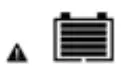 | Battery level shows full, battery frame blink, fault icon blink. |
| Battery over heating | Red slowly flashing | — |  | Battery level shows current value, battery frame blink, fault icon blink. |
| Controller over temperature | Red slowly flashing | Green slowly flashing |  | Battery level shows current value, battery frame blink, fault icon blink. |
| System voltage error | Red slowly flashing | Fast flashing in green |  | Battery level shows current value, battery frame blink, fault icon blink. |
SETTINGS
- Clear the generated energy
In the PV power interface, long press the “ENTER” button until the value flashes. Then it enters the reset mode; press the “ENTER” button again to confirm and reset. - Switch the battery temperature unit
In the battery temperature interface, long press the “ENTER” button to switch the unit. - Battery type
Supported Battery TypesLead-acid battery Sealed(default) Gel Flooded User Lithium battery LiFePO4(4S/12V;8S/24V;16S/48V) Li(NiCoMn)O2 (3S/12V;6S/24V;12S/48V) User
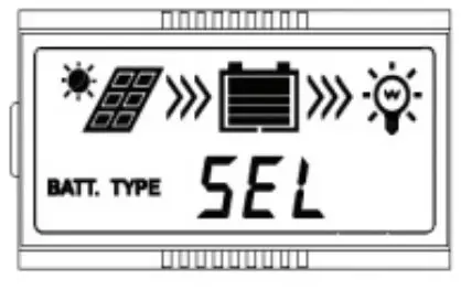
Setting the battery type via the LCD
- Sealed (Default)

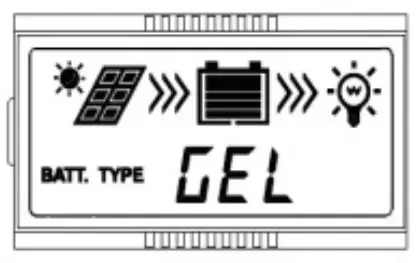
- Gel
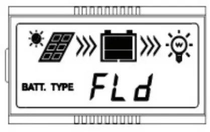
- Flooded
- User (Apply to “MT50” and “PC software “Solar Station Monitor”)
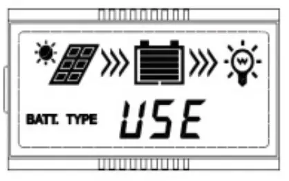
Operation
On the battery voltage interface, long press the “ENTER” button until the battery type interface flashes. Then press the “SELECT” button to change the battery type, and press the “ENTER” button to confirm.
![]()
CAUTION
The controller can only set the lead-acid battery type. The lithium battery type needs to be set through the PC software or APP.
Setting the battery type via the PC software or APP software
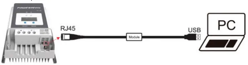
- PC software
Connect the controller and the PC through the USB to the RS485 converter, and set the controller’s parameters through the PC software. Please refer to the cloud platform manual for the specific setting.
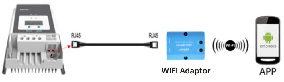
- APP software
Connect the controller and the WIFI module or Bluetooth module through a standard network cable (parallel cable). The mobile phone APP sets the controller’s parameters through the WIFI signal or the Bluetooth signal. For the specific setting, please refer to the cloud APP manual.
![]()
CAUTION
The controller can only set the lead-acid battery type. The lithium battery type needs to be set through the PC software or APP
Battery voltage control parameters
Lead-acid Battery Parameters
The parameters are measured in the condition of 12V/25°C. Please double the values in the 24V system and quadruple the values in the 48V system.
| Voltage control parameters | Sealed | GEL | FLD | User |
| Over voltage disconnect voltage | 16.0V | 16.0V | 16.0V | 9~17V |
| Charging limit voltage | 15.0V | 15.0V | 15.0V | 9~17V |
| Over voltage reconnect voltage | 15.0V | 15.0V | 15.0V | 9~17V |
| Equalize charging voltage | 14.6V | — | 14.8V | 9~17V |
| Boost charging voltage | 14.4V | 14.2V | 14.6V | 9~17V |
| Float charging voltage | 13.8V | 13.8V | 13.8V | 9~17V |
| Boost reconnect charging voltage | 13.2V | 13.2V | 13.2V | 9~17V |
| Low voltage reconnect voltage | 12.6V | 12.6V | 12.6V | 9~17V |
| Under voltage warning reconnect voltage | 12.2V | 12.2V | 12.2V | 9~17V |
| Under voltage warning voltage | 12.0V | 12.0V | 12.0V | 9~17V |
| Low voltage disconnect voltage | 11.1V | 11.1V | 11.1V | 9~17V |
| Discharging limit voltage | 10.6V | 10.6V | 10.6V | 9~17V |
| Equalize Duration | 120minutes | — | 120minutes | 0~180minutes |
| Boost Duration | 120minutes | 120minutes | 120minutes | 10~180minutes |
- To change these parameters, select “User” battery type.
- The following rules must be observed when modifying the parameter’s value in user battery type (factory default value is the same as sealed type):
OPERATION:
NOTE:
- When the battery type is sealed, gel, flooded, the adjusting range of equalize duration is 0 to 180min and boost duration is 10 to 180min.
- The following rules must be observed when modifying the parameters value in user battery type (factory default value is the same as sealed type):
a. Over Voltage Disconnect Voltage > Charging Limit Voltage ≥ Equalize Charging Voltage ≥ Boost Charging Voltage ≥ Float Charging Voltage > Boost Reconnect Charging Voltage.
b. Over Voltage Disconnect Voltage > Over Voltage Reconnect Voltage
c. Low Voltage Reconnect Voltage > Low Voltage Disconnect Voltage ≥ Discharging Limit Voltage.
d. Under Voltage Warning Reconnect Voltage > Under Voltage Warning Voltage ≥ Discharging Limit Voltage.
e. Boost Reconnect Charging Voltage > Low Voltage Disconnect Voltage
![]()
CAUTION
Please refer to user guide or contact with the sales for the detail of setting operation.
Lithium battery voltage parameters
| Battery charging setting | LFP | LNCM | ||||
| LFP4S | LFP8S | LCNM3S | LCNM6S | LCNM7S | User* | |
| Over voltage disconnect voltage | 14.8V | 29.6V | 12.8V | 25.6V | 29.8V | 9~17V |
| Charging limit voltage | 14.6V | 29.2V | 12.6V | 25.2V | 29.4V | 9~17V |
| Over voltage reconnect voltage | 14.6V | 29.2V | 12.5V | 25.0V | 29.1V | 9~17V |
| Equalize charging voltage | 14.5V | 29.0V | 12.5V | 25.0V | 29.1V | 9~17V |
| Boost charging voltage | 14.5V | 29.0V | 12.5V | 25.0V | 29.1V | 9~17V |
| Float charging voltage | 13.8V | 27.6V | 12.2V | 24.4V | 28.4V | 9~17V |
| Boost reconnect charging voltage | 13.2V | 26.4V | 12.1V | 24.2V | 28.2V | 9~17V |
| Low voltage reconnect voltage | 12.8V | 25.6V | 10.5V | 21.0V | 24.5V | 9~17V |
- The following rules must be observed when modifying the parameter values in User for a lithium battery
A. Over Voltage Disconnect Voltage > Over Charging Protection Voltage(Protection Circuit Modules(BMS))+0.2V;
B. Over Voltage Disconnect Voltage > Over Voltage Reconnect Voltage = Charging Limit Voltage ≥ Equalize Charging Voltage = Boost Charging Voltage ≥ Float Charging Voltage > Boost Reconnect Charging Voltage;
C. Low Voltage Reconnect Voltage > Low Voltage Disconnect Voltage ≥
Discharging Limit Voltage.
D. Under Voltage Warning Reconnect Voltage > Under Voltage Warning Voltage ≥ Discharging Limit Voltage;
E. Boost Reconnect Charging voltage > Low Voltage Reconnect Voltage;
F. Low Voltage Disconnect Voltage ≥ Over Discharging Protection Voltage (BMS)+0.2V
WARNING
- The voltage parameters of a lithium battery can be set according to the lithium battery BMS’s voltage parameters.
- The required accuracy of BMS shall be no higher than 0.2V. We will not assume any responsibility for the system abnormal when the accuracy of BMS is higher than 0.2 v.
ADDITIONAL INFO
PROTECTION
WARNING
- Controllers have no battery reverse protection. Do not reverse the battery during the wiring. Otherwise, the controller may be damaged.
| Protection | Instruction |
| PV current/ power-limiting protection | When the PV array’s actual charging current or power exceeds the controller’s rated charging current or power, the controller charges the battery as per the rated current or power. |
| PV short-circuit protection | When not in the PV charging state, the controller will not be damaged in the case of short-circuiting in the PV array. |
WARNING It is forbidden to short-circuit the PV array during charging. Otherwise, the controller may be damaged. | |
| PV reverse polarity protection | When the PV array’s polarity is reversed, the controller may not be damaged and resume work after the mis-wiring is corrected. |
CAUTION If the PV array is reversed and its actual power is 1.5 times the controller’s rated power, the controller may be damaged. | |
| Night reverse charging protection | Prevent the battery from discharging to the PV module at night. |
| Battery over voltage protection | When the battery voltage reaches the over voltage disconnect voltage, the PV array will automatically stop charging the battery to prevent the battery damage caused by overcharging. |
| Battery over discharging protection | When the battery voltage reaches the low voltage disconnect voltage, the battery discharging is automatically stopped to prevent battery damage caused by over discharging. |
CAUTION When a load is connected to the battery and the load is connected to the controller’s (Load) dry contact, the battery over-discharge protection takes effect. | |
| Battery over heating protection | The controller detects the battery temperature through an external temperature sensor. The battery stops working when its temperature exceeds 65°C and resumes work when its temperature is below 55°C. |
| Lithium battery low temperature protection | When the temperature detected by the optional temperature sensor is lower than the Low Temperature Protection Threshold(LTPT), the controller stops charging and discharging automatically. When the detected temperature is higher than the LTPT, the controller resumes work automatically. (The LTPT is0 °C by default and can be set within the range of 10 ~ -40 °C. Detail settings refer to the LTPT V1.0.) |
| Controller Overheating* | An internal temperature sensor can detect the internal temperature of the controller. The controller stops working when the internal temperature exceeds 85°C and resumes work when the internal temperature is below 75°C. |
| TVS high voltage transients protection | The controller’s internal circuitry is designed with Transient Voltage Suppressors (TVS), which can only protect against high- voltage surge pulses with less energy. Suppose the controller is to be used in an area with frequent lightning strikes. In that case, it is recommended to install an external surge arrester. |
* When the control’s internal temperature is 81°C, the reducing power charging mode is turned on, reducing the charging power of 5%, 10%, 20%, 40% every increase of 1°C. If the internal temperature is greater than 85°C, the controller stops charging. When the internal temperature is not more than 75°C, the controller will resume charge as per the rated power.
Example – 48V System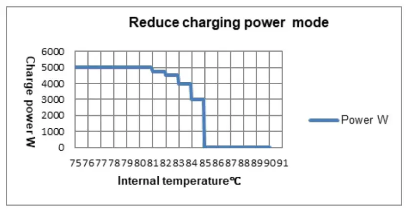
TROUBLESHOOTING
| Issue | Fault | Solution | |
| Charging LED is OFF during daytime when sunshine falls on PV array properly | PV array open-circuit | Confirm whether the connection of the PV array is correct and tight | |
| The wire connection is correct; the controller is not working. | The battery voltage is lower than 8V. | Please check the voltage of the battery(at least 8V voltage to activate the controller). | |
| Battery frame blink, fault icon blink |  | Battery over voltage | Check whether the battery voltage is higher than OVD (over voltage disconnect voltage) and disconnect the PV array connection. |
 | Battery over discharged | ① When the battery voltage is restored to or above LVR(low voltage reconnect voltage), the load recovers.② Other ways to recharge thebattery. | |
| Battery over heating | While the battery temperature decline to 55°C or below, the controller resumes work. | ||
MAINTENANCE
The following inspections and maintenance tasks are recommended at least two times per year for the best performance.
- Make sure no block on airflow around the controller. Clear up any dirt\ and fragments on the radiator.
- Check all the naked wires to ensure insulation is not damaged for sun exposure, frictional wear, dryness, insects or rats, etc. Repair or replace some wires if necessary.
- Check and confirm that LED is consistent with required. Pay attention to any troubleshooting or error indication. Take necessary corrective action.
- Confirm that all terminals have no corrosion, insulation damaged, high temperature, or burnt/discolored sign, and tighten terminal screws to the suggested torque.
- Clear up dirt, nesting insects, and corrosion in time.
- Check and confirm that the lightning arrester is in good condition.
Replace a new one in time to avoid damaging the controller and even other equipment.
WARNING
Risk of electric shock!
Ensure that all the power is turned off before the above operations, and then follow the corresponding inspections and operations.
SPECIFICATIONS
| Model: | MP3749 |
| Electrical Parameters | |
| System rated voltage | 12/24/36/48VDC or Auto |
| Controller working voltage range | 8V~32V |
| Lead-acid battery type | Sealed(default), GEL, FLD, and user- defined. |
| Lithium battery type | LiFePO4/ Li(NiCoMn)O2/ User |
| Battery fuse | 80A/ 58V |
| Rated charging current | 60A |
| Rated charging power | 750W/12V, 1500W/24V |
| Max. PV open-circuit voltage | 100V (at the lowest temperature) 92V (at 25°C) |
| MPPT voltage range | (Battery voltage +2V) ~72V (at 25°C) |
| MPPT tracking efficiency | ≥99.5% |
| Max. conversion efficiency | 98.0% |
| Full load efficiency | 97.0% |
| Temperature compensate coefficient | -3mV/°C/2V(Default) |
| Self-consumption | 98mA/12V; 60mA/24V; 50mA/36V;46mA/48V |
| Grounding type | Common negative grounding |
| Dry contact | Rated value: 5A/30VDC; Max. value: 0.5A/60VDC |
| Communication method | RS485 (5VDC/200mA, Two RJ45 ports in parallel)① |
| LCD backlight time | Default: 60S, Range:0~999S (0S: the backlight is ON all the time) |
| Mechanical parameters | |
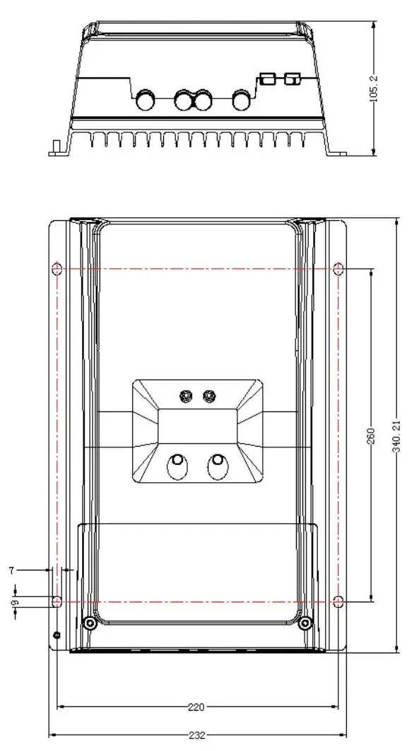
| Dimension | 340×232×105.2mm |
| Mounting dimension | 260×220mm |
| Mounting hole size | Ø7 |
| Wire size | 2AWG/ 35mm2 |
| Recommended cable | 6AWG/ 16mm2 |
| Net Weight | 3.5kg |
| Environmental Parameters | |
| Working environment temperature | -25°C ~ +60°C (when the working temperature reaches 45°C or above, the charging power and load power will be reduced appropriately; working of full load is not supported.) |
| LCD temperature range | -20°C ~ +70°C |
| Storage temperature | -30°C ~ +85°C |
| Relative humidity range | 5% ~ 95% (N.C.) |
| Enclosure | IP20 |
| Pollution degree | PD2 |
| Certification | |
| Category | Standard |
| Safety | EN/IEC62109-1 |
| EMC | EN61000-6-1/EN61000-6-3 |
| FCC | 47 CFR Part 15, Subpart B |
| ROHS | IEC62321-3-1 |
DIMENSIONS
Distributed by:
Electus Distribution Pty Ltd
46 Eastern Creek Dr,
Eastern Creek NSW 2766 Australia
Ph 1300 738 555
Int’l +61 2 8832 3200
Fax 1300 738 500
www.electusdistribution.com.au
Made in China


 Solar Mppt Charge Controller User Manual")