![]()
HUIZHOU EPEVER TECHNOLOGY CO., LTD.
※Thank you for selecting the Tracer LPLI series MPPT solar charge controller with built-in LED driver. Please read this manual carefully before using the product and pay attention to the safety information.
MPPT Solar Charge Controller
—with built-in LED Driver
Safety Information
- Read all of the instructions in the manual before installation.
- DO NOT disassemble or attempt to repair the controller.
- Install external fuse or breaker as required.
- Do disconnect the solar module and fuse/ breakers near to battery before installing or moving the controller.
- Power connections must remain tight to avoid excessive heating from a loose connection.
- Only charge batteries that comply with the parameters of controller.
- Battery connection may be wired to one battery or a bank of batteries.
- Risk of electric shock, the PV and load can produce high voltages when the controller is working.
Overview
The Tracer LPLI series MPPT solar charge controller combines solar charge controller and LED constant current driver into one unit which is ideal for solar LED Lighting,
especially when dimmer function is needed. The advanced Maximum Power Point Tracking charging methods enables the system charging and discharging management
to obtain the most radical optimization. Increase the system flexibility, yet lower down the system cost. The features are listed below:
- Advanced Maximum Power Point Tracking (MPPT) technology, with tracking efficiency no less than 99.5%
- Maximum conversion efficiency of 98%
- Accurately recognizing and tracking of multiple power points
- Ultra-fast tracking speed and guaranteed tracking efficiency
- Adopt high quality components of ST,IR and Infineon, make sure product using lifespan
- Apply to lead-acid battery and lithium battery
- Lithium battery self-activating function
- Lithium battery low temperature protection function
- Charging current limit, with settable current
- Lithium battery limit current in low temperature
- Intelligent power mode with 365-day lighting control technology
- Load reduce power automatically
- Digital precision constant current control and the control accuracy are less than ±2%
- Maximum output efficiency of 96%
- PV and Load power limitation function
- The output current can be adjusted among the rated power and current range
- Real-time energy statistics function
- Monitoring and setting parameter via Mobile APP and RC10 with IR function
- Aluminum housing for better cooling
- Wide working environment temperature(-40℃~60℃)
- IP68 waterproof degree
Product Features
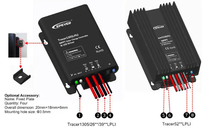
| ① | Temperature Sensor | ⑤ | Charging Status LED indicator |
| ② | PV Positive and Negative Wires | ⑥ | Battery Status LED indicator |
| ③ | Battery Positive and Negative Wires | ⑦ | Infrared Receiver Module |
| ④ | Load Positive and Negative Wires | ⑧ | Infrared LED |
Wiring
- Reference for Serial connection of LED
| System Voltage | Serial connection | Min. Output Voltage | Max. Output Voltage |
| 12V | 5~18 LED | 15V | 60V |
| 24V | 10~18 LED | 30V | 60V |
![]() NOTE: The above one LED (1W, 3.3V) is calculated. If the user uses the unconventional LED, The actual LED voltage must less than the Max. Load Output Voltage.
NOTE: The above one LED (1W, 3.3V) is calculated. If the user uses the unconventional LED, The actual LED voltage must less than the Max. Load Output Voltage.![]() WARNING:DO NOT electric shock! The product built-in boost LED driver, the output voltage is higher than the human safety voltage.
WARNING:DO NOT electric shock! The product built-in boost LED driver, the output voltage is higher than the human safety voltage.
Connection Order
- Connect components to the charge controller in the sequence as shown above and pay much attention to the “+” and “-”. Please don’t insert the fuse or turn on the breaker during the installation. When disconnecting the system, the order will be reserved.
- After power on the controller, check the battery LED indicator on the controller, it will be green. If it’s not green, please refer to chapter 9.
- Connecting a fuse in series through battery positive (+) in the circuit and the battery circuit fuse must be 1.25 to 2 times to the rated current. The installed distance is within 150mm.
![]() NOET: The controller can only charge or discharge alone, but it can carry out the discharge process to check the load preferentially.
NOET: The controller can only charge or discharge alone, but it can carry out the discharge process to check the load preferentially. 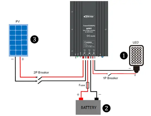
Load self-test function
The load is ON when the controller power on 10seconds. After 10 seconds it will restore to set working mode.
LED Indicators
| Indicator | Color | Status | Instruction |
| Green | On Solid | PV connection normal but low voltage(irradiance) from PV, no charging | |
| Green | OFF | No PV voltage(night time) or PV connection problem | |
| Green | Slowly Flashing(1 Hz) | In charging | |
| Green | Fast Flashing(4Hz) | PV Over voltage | |
| Green | On Solid | Normal | |
| Green | Slowly Flashing(1 Hz) | Full | |
| Green | Fast Flashing(4Hz) | Over voltage | |
| Orange | On Solid | Under voltage | |
| Red | On Solid | Over discharged Low temperature | |
| Red | Fast Flashing(4Hz) | Battery Overheating | |
| All indicators | Green orange | Flashing two times | Set parameters successfully |
Load Working Mode
- Manual Mode
- Light ON/OFF(Default)
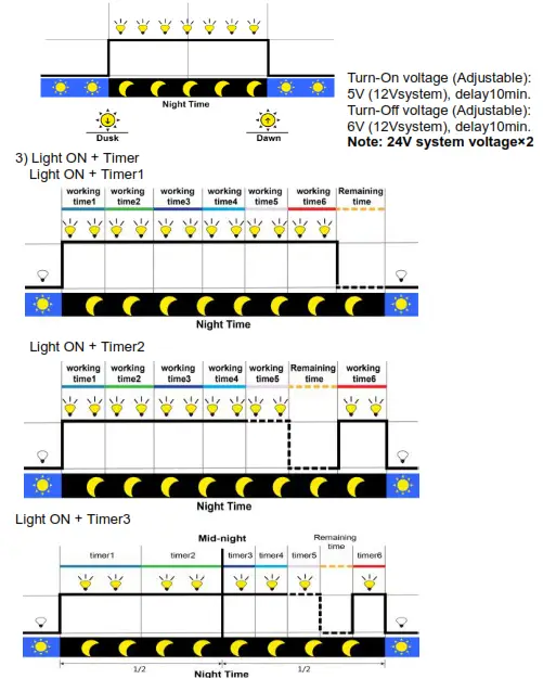
4) Real-time Control
Control the load ON/OFF time through setting real-time clock.
5) Intelligent Power Reduction Mode
When the battery voltage goes lower than the “Reduce Power Start Voltage (adjustable),” the intelligent power reduction mode is enabled. The LED output current is automatically reduced in linear with the battery’s voltage drop. When the battery voltage goes lower than the “Reduce Power End Voltage (adjustable),” the LED output current is 2% of the rated load current. The minimum percentage can be set to 1%. Also, when the battery voltage is higher than “Reduce Power Start Voltage,” the controller exits the intelligent power reduction mode.![]() NOTE: In Light ON/OFF and Light ON/Timer mode, the load is turned on after a 1-minute delay,the delay time can be set.
NOTE: In Light ON/OFF and Light ON/Timer mode, the load is turned on after a 1-minute delay,the delay time can be set.
Setting Operation
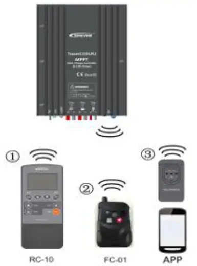
There are three methods that it can realize controller load modes and parameters through IR function:
- IR Remote Control—RC10
- Super Parameter Programmer—FC-01
This method can realize one-key setting operation which is suitable for bulk quantity products setting or applied in the projects. - Mobile APP+eBox-WIFI&IR-01/02 Real-time monitoring and setting the parameters
Note: Please refer to the user manual of handheld device
Protection
| Protection | Conditions | Status |
| PV Reverse Polarity | The PV can be reversely connected with a controller when: ✓Only the PV is connected with the controller; ✓The battery is positively connected, and the open-circuit voltage of the PV is lower than 85V(This requirement is only for Tracer26/39/5210LPLI). | The controller is not damage |
| Battery Reverse Polarity | When the PV is not connecting or connection reversed, the battery can be reversed. WARNING: Controller will be damaged when the PV connection is correct and battery connection reversed! | |
| Battery Over Voltage | The battery voltage reaches to the OVD | Stop charging |
| Battery Over Discharge | The battery voltage reaches to the LVD | stop discharging |
| Battery Overheating | Temperature sensor is higher than 65°C | Output is OFF |
| Temperature sensor is less than 55°C | Output is ON | |
| Lithium battery Low Temperature (Default 35t) | Temperature sensor is less than the low temperature value | Lithium battery stop charging |
| Temperature sensor is higher than the low temperature value | Lithium battery charging | |
| Lithium battery limit current in low temperature | Limit current temperature T1>T2>T3>T4 >T5>T6 Limit currentI1>12>13>14>15>16 | When the temperature is lower than T1, the charging current is 11; when the temperature is lower than T2, the charging current is 12; and so on. However, when the temperature rises gradually from T4 to T1, it is |
| performed at I4. | ||
| Load Short Circuit | Load current ≥2.5 times rated current One short circuit, the output is OFF 5s; Two short circuit, the output is OFF 10s; Three short circuit, the output is OFF 15s;Four short circuit, the output is OFF 20s; Five short circuit, the output is OFF 25s; Six short circuit, the output is OFF | Output is OFF Clear the fault: Restart the controller or wait for one night-day cycle (night time>3 hours). |
Troubleshooting
| Faults | Possible reasons | Troubleshooting |
| LED Charging indicator turn off during daytime when sunshine falls on PV modules properly | PV array disconnection | Confirm that PV and battery wire connections are correct and tight |
| No LED indicator | Battery voltage maybe less than 8.5V | Measure battery voltage with the multi-meter. Min.8.5V can start up the controller |
| Battery LED indicator green fast Flashing | Battery over voltage | Check if battery voltage is higher than OVD, and disconnect the PV |
| Battery LED indicator red | Battery over discharged | When the battery voltage is restored to or above LVR point (low voltage reconnect voltage), the load will recover |
| Battery LED indicator red flashing | Battery Overheating | The controller will automatically turn the system off. But while the temperature decline to be below 50 °C, the controller will resume. |
| Powering on normally, the load is off | GThe connecting wires are error or virtually connected ”)Load mode is not appropriate. ‘ 3)This controller does not match with the LED light. ‘i)Output short circuit. | ‘0 Check the connecting cable. (2) Check the load’s mode and parameters. The voltage of LED light is not X within the output voltage range of controller. (4)Check the connecting cables and LED light. |
| The dimming function is invalid | The controller does not match with the LED light source. This product is a step-up voltage control, If input voltage is lower than the rated voltage, it is not working. | GReplace the LED light ‘-)Reducesystem rated voltage grade and replace the product model For example 24V system change to 12V system, and replace the corresponding controller |
| Parameter settings fail | Infrared communication error | Refer to handheld the user device manual |
- When the battery is over discharged, the battery indicator will be red and the load will be off all the time before the voltage is more than the Low Voltage Reconnect Voltage (LVRV). In order to judge the system is normal or not, firstly measuring the battery voltage whether is more than LVRV, if not, restarting the controller to detect the load whether it is normal. NOTE: The LVRV can be set, but it must pay more attention that it maybe damages the battery if the LVRV is too low.
Technical Specifications
| Item | Tracer1305LPLI | Tracer2606LPLI I Tracer3906LPLI I Tracer5206LPLI I Tracer2610LPLI I Tracer3910LPLI I Tracer5210LPLI | ||||||
| Nominal system voltage | 12VDC | 12/24VDC | ||||||
| Battery input voltage range | 8.5- -16VDC | 8.5- -32VDC | ||||||
| Rated charge current* | 10A/12V | 10A | 15A | 20A | 10A | 15A | 20A | |
| Rated charge power | 130W/12V | 130W/12V: 260W/24V | 200W/12V: 400W/24V | 260W/12V: 520W/24V | 130W/12V:260W/24V | 200W/12V: 400W/24V | 260W/12V: 520W/24V | |
| Max. PV open circuit voltage | 50V(Min. Temp.) 45V(25 C) | 60V(at minimum operating environment temperature) 46V(at 25 C’ environment temperature) | 100V(at minimum operating environment temperature) 92V(at 25 C environment temperature) | |||||
| MPP Voltage range | ( Battery voltage+2V)- -36V | ( Battery voltage+2V)- -72V | ||||||
| Max. output current | 3.3A | 3.3A | 4.5A | 6.6A | 3.3A | 4.5A | 6.6A | |
| Max. output power | 100W | 100W | 130W | 200W | 100W | 130W | 200W | |
| Output voltage range | ( Max. battery voltage+2V)- 46V | ( Max. battery voltage+2V)-58V | ||||||
| Load open circuit voltage | 46V | 58V | ||||||
| Load over voltage protection | 50V | 63V | ||||||
| Maximum output efficiency | 96% | |||||||
| Output current control accuracy | 52% | |||||||
| Battery Type | Lead-acid battery: Sealed(defaultyGel/Flooded/User; Lithium battery:LiFePO4/Li-NiCoMn/User | |||||||
| Lead-acid | Equalization Voltage | Sealed:14.6V; Flooded:14.8V;User:9-17V (24Vsystem x 2) | ||||||
| Boost Voltage | Sealed:14.4V;Ge1:14.2V;Flooded:14.6V;User:9-17V(24Vsystem x 2) | |||||||
| Float Voltage | Sealed/Gel/Flooded:13.8V;User:9-17V(24Vsystem x 2) | |||||||
| Low Voltage Reconnect Voltage | Sealed/Gel/Flooded:12.6V;User:9-17V(24Vsystem x 2) | |||||||
| Low Voltage Disconnect Voltage | Sealed/Gel/Flooded:11.1V;User:9-17V(24Vsystem x 2) | |||||||
| Lithium | Boost Charging Voltage | LiFePO4(4s):14.5V/Li-NiCoMn(3s):12.5V/User:9-17V(24Vsystem x 2) | ||||||
| Low Voltage Reconnect Voltage | LiFePO4(4s):12.8V/Li-NiCoMn(3s):10.5V/User:9-17V(24Vsystem x 2) | |||||||
| Low Voltage Disconnect Voltage | LiFePO4(4s):11.1V/Li-NiCoMn(3s):9.3V/User:9-17V(24Vsystem x 2) | |||||||
| Self-consumption | 515mN12V;522mA/24V | |||||||
| Communication | IR communication | |||||||
| Working environment Tem. | -40t – – +60t | |||||||
| Enclosure | IP68(1.5m.72h) | |||||||
| Dimension | 124 x89x3Omm I150x93.5×32.7mm 153x 105×52.1mm 124 x89 x3Omm 1150 x93.5×32.7mm 153x105x52.1mm | |||||||
| Mounting hole size | 03.5mm | |||||||
| Mounting size | 88x 76mm I 120x83mm | 120x94mm | 88x76mm I 120x83mm | 120x94mm | ||||
| Power cable | PV/BAT:14AWG(2.5mm‘) LOAD:18AWG(1.0mm2) | PV/BAT:12AWG(4mmi) LOAD:16AWG(1.5mm2) | PV/BAT:14AWG(2.5me) LOAD:18AWG(1.0mm2) | PV/BAT:12AWG(4me) LOAD:16AWG(1.5mm2) | ||||
| Net weight | 0.52kg I 0.52kg I 0.71kg | 1.18kg | 0.52kg I 0.71kg | 1.18kg | ||||
★The controller has the limit charge current function, the current can be set via the APP software and RC10.
Any changes without prior notice! Version number:V2.4
HUIZHOU EPEVER TECHNOLOGY CO., LTD.
Tel:+86-10-82894896/82894112/+86-752-3889706
Website:www.epever.com


 Solar Mppt Charge Controller User Manual")


