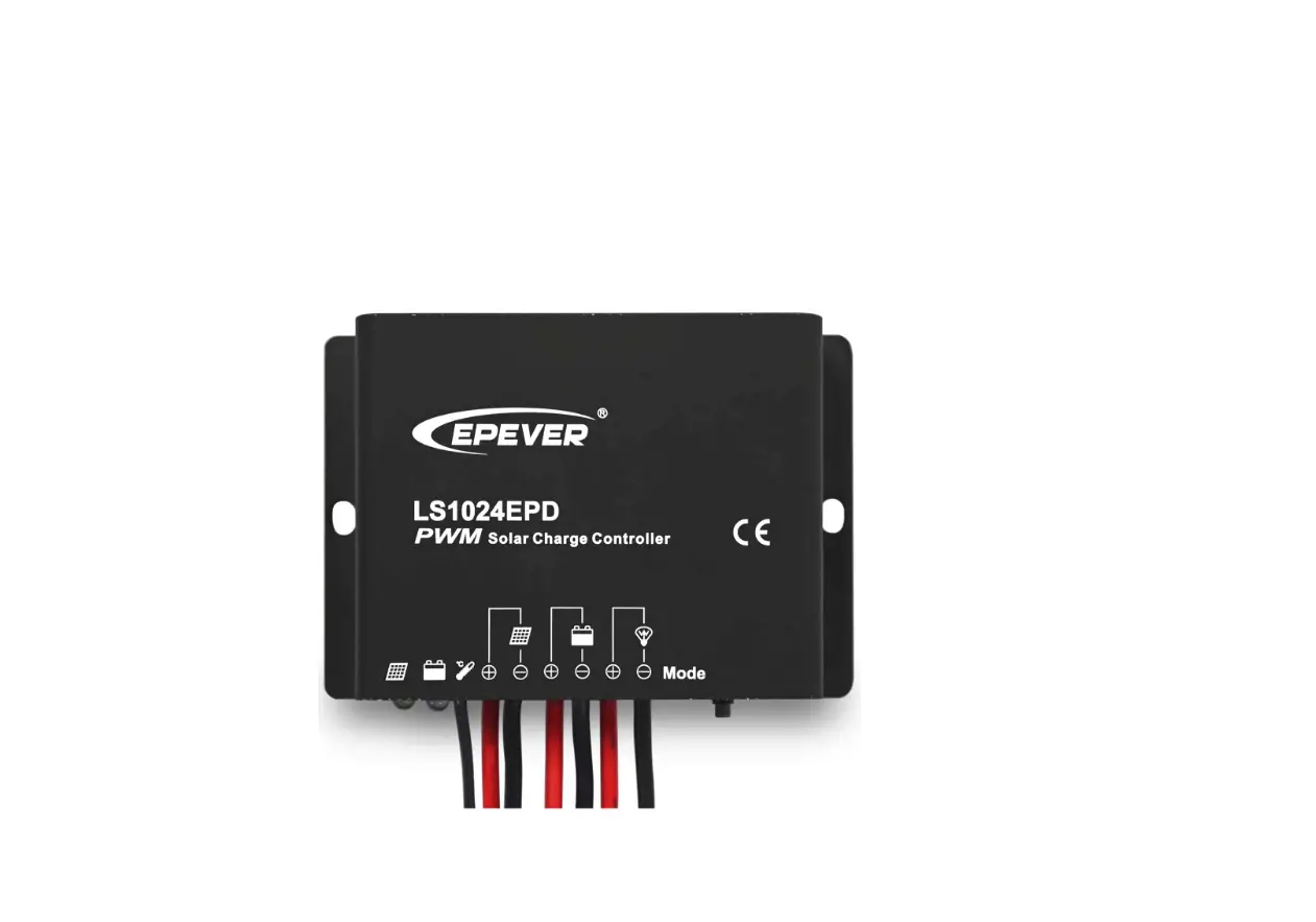
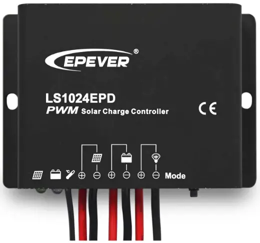
EPEVER LS1024EPD Solar Charge Controller
General Information
LS EPD series solar charge controller adopts the most advanced digital technique and operates fully automatically. It is ideal for extreme environments with corrosion, dust, water, etc., and has various unique functions:
- Electronic protection: Over charging, over-discharging, overload, short circuit, and reverse protection of solar module
- High efficient Series PWM charging increases the battery lifetime and improves the solar system performance
- Widely used, automatically recognizes day/night
- Battery LED to indicate battery status
- Industrial design, the wide application range
- Digital tube menu, only one key solve all setting simply
- Intelligent timer function with 1~13 hours option
- IP67 protection
Features and Mounting
Do not install this product in humid, salt spray, corrosion, greasy, flammable, explosive, dust accumulative, or other severe environments.
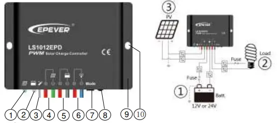
| ① | Charging Status LED indicator | ⑥ | Load Terminals |
| ② | Battery Status LED indicator | ⑦ | Digital tube |
| ③ | Temperature Sensor | ⑧ | Key |
| ④ | Solar Module Terminals | ⑨ | Aluminum housing |
| ⑤ | Battery Terminals | ⑩ | Mounting hole Φ5 |
Mounting
- Connect components to the charge controller in the sequence “①Battery > ②Load > ③ PV” and pay much attention to the “+” and “-.” Always power the battery first.
- Check whether the battery indicator is green after powering the battery. If it’s not green, please refer to chapter 4.
- The fast-acting fuse should be installed as close to the battery. The suggested distance is within 150mm.
Indicators Description and Operation
Indicator Status Description
| Charging Status LED indicator | Green | On Solid | Normal |
| Green | Fast Flashing | Overvoltage | |
|
Battery Status LED indicator | Green | On Solid | Normal |
| Green | Slowly Flashing | Full | |
| Orange | On Solid | Under voltage | |
| Red | On Solid | Over discharged | |
| Radix Point of Digital tube (Load indicator) | Red | On Solid | Load ON |
| Red | Slowly Flashing | Over Load | |
| Red | Fast Flashing | Short Circuit |
Operation
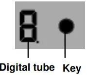
- After Powering on, disconnect the PV or connect the PV (Voltage<5V), and the light of the digital tube point goes on; Connect the PV (Voltage>6V), and the light of the digital tube point goes off.
- The key can be used to operate switching on/off the load (Manual control) or clearing the faults
- Press the button over 5S to light the digital tube and enter the parameter browsing mode. End-users can cycle browse the parameter by clicking the button.
- After the digital tube displays the value to be configured, release the key and wait for 15S. The Digital Tube stops flashing; the configuration is successful.
Load mode
- Manual Control: Control the load via the button.
- Light ON/OFF Light ON + Timer

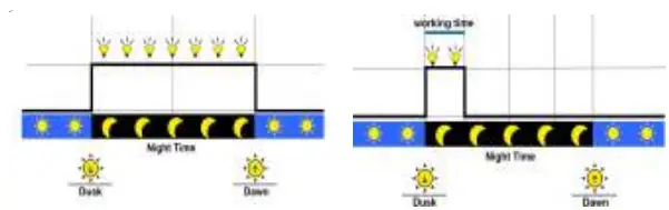
Note: In the mode of Light ON/OFF and Light ON/Timer, the Load is turned on after 10Min. Delay.
- Test Mode (Default): Test Mode is the same as Light Control Mode without delay.
The correspondence table of Load Work Mode & LED digital tube value
| Value | Working mode | Value | Working mode |
| 0 | Light ON / OFF | 0. | Light ON + 8 hours |
| 1 | Light ON + 1 hours | 1. | Light ON + 9 hours |
| 2 | Light ON + 2hours | 2. | Light ON + 10 hours |
| 3 | Light ON + 3hours | 3. | Light ON + 11 hours |
| 4 | Light ON + 4 hours | 4. | Light ON + 12 hours |
| 5 | Light ON + 5 hours | 5. | Light ON + 13 hours |
| 6 | Light ON + 6 hours | 6. | Manual Control |
| 7 | Light ON + 7 hours | 7. | Test Mode |
Troubleshooting
| Faults | Possible reasons | Troubleshooting |
| Charging LED is off during daytime when sunshine falls on PV modules properly | PV array disconnection | Check that PV and battery wire connections are correct and tight |
|
Battery indicator green fast flashing | Battery voltage higher than over voltage disconnect voltage | 1. Disconnect the solar array and measure whether the battery voltage is too high; 2. Change the controller; 3. Change the battery |
| The battery indicator flashes red and loads not working | Battery over-discharged | The controller cut off the output automatically. The indicator will return to green automatically when fully |
| The radix point of digital tube fast flashing and load not working |
Short circuit | Clear short circuit. It is reactivated after being delayed 10 seconds for the first time. If over one time, press the key to clear the error, and the controller will resume after 3s or restart the controller |
| Please reduce the number of electric | ||
| equipment. | ||
| The radix point of the digital tube is slowly flashing, and loads are not working |
Overload | When load power reaches 1.25-1.5 times, 1.5-2 times, and 2 times more than the nominal value, the controller will turn off loads in 60 seconds, 5 seconds, and 1 second. Press the key to clear the error, |
| and the controller will resume after 3s or | ||
| restart the controller |
Technical Specifications
| Item | LS1024EPD | LS2024EPD |
| Nominal system voltage | 12/24VDC Auto | 12/24VDC Auto |
| Max. PV input voltage | 50V | 50V |
| Rated current | 10A | 20A |
| Equalize Voltage | 14.8V(12V); 29.6V(24V) | |
| Boost Voltage | 14.4V(12V); 28.8V(24V) | |
| Float Voltage | 13.7V(12V); 27.4V(24V) | |
| Low Voltage Reconnect Voltage | 12.6V(12V); 25.2V(24V) | |
| Low Voltage Disconnect Voltage | 11.2V(12V); 22.4V(24V) | |
| Self-consumption | ≤4.58mA(12V); ≤6.01mA(24V) | |
| Temperature compensation coefficient | -5mV/℃/2V(25℃) | |
| Environment temperature | -35℃ ~ +50℃ | |
| Enclosure | IP67 | |
| Dimension (L x W x H) | 108.5mm × 75mm × 25.6mm | |
| Mounting size | 100.5mm | |
| Mounting hole size | Φ5 | |
| Power cable | PV/BAT/LOAD: 4.0mm2 | PV/BAT/LOAD: 6.0mm2 |
| Net weight | 410g | 435g |
Any changes without prior notice! Version number: V2.2
- Website: www.epever.com
- Tel: +86-752-3889706


