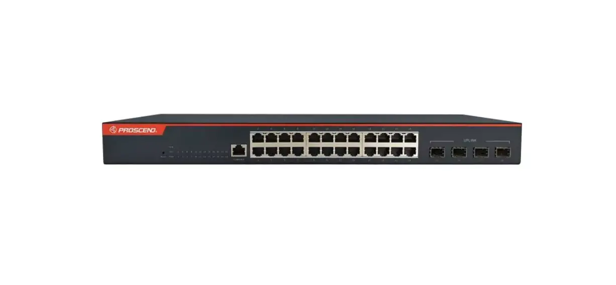
PROSCEND 850X-28 24-Port GbE + 4-Port 10G SFP+ Managed Switch Installation Guide
Connecting Power
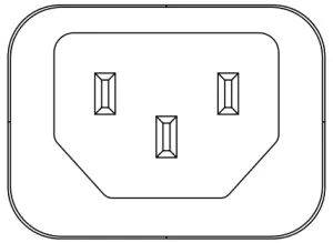
The 850X-28 can automatically adjust the AC power setting to adapt to any voltage supply in the range 100~240 VAC 50/60Hz. Connect the one end of the supplied AC power cord to the AC power connector on the rear panel and the other end into a properly grounded power outlet.
LED Indicators
| LED | Color | Description |
| PWR | On: Green | Power on. |
| Off | Power off. | |
| SYS | On: Green | System is ready. |
| Blinking | System is booting up. | |
| Off | No power or system boot up failed. | |
| ALM | On: Red | Alarm for system failure because of overheat or wrong voltage. |
| Off | Switch is in operation with normal condition. | |
| 1~24 LAN Port Link/Act | On: Green | Ethernet LINK UP at 1000Mbps. |
| On: Amber | Ethernet LINK UP at 10/100Mbps. | |
| Blinking | Ethernet traffic detected. | |
| Off | Ethernet LINK DOWN. | |
| 25~28 SFP+ Port Link/Act | On: Blue | LINK UP at 10Gbps. |
| On: Green | LINK UP at 1000Mbps. | |
| Blinking | Traffic detected. | |
| Off | LINK DOWN. |
RJ45 Connector Pinouts
The pin assignment of RJ45 connector is shown in the following table.
- 8-pin RJ45
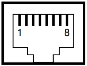
| Pin | Description | PoE Pinouts |
| 1,2 | T/Rx+,T/Rx− | V+ |
| 3,6 | T/Rx+,T/Rx− | V− |
| 4,5 | T/Rx+,T/Rx− | X |
| 7,8 | T/Rx+,T/Rx− | X |
Console Connection
- CONSOLE
The console port on the front panel is for local management by using a terminal emulator or a computer with terminal emulation software.
- DB9 connector connect to computer COM port
- Baud rate: 115200bps
- 8 data bits, 1 stop bit
- None Priority
- None flow control
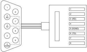
To connect the host PC to the console port, a RJ45 (male) connector-to-RS232 DB9 (female) connector cable is used (included in package). The RJ45 connector of the cable is connected to the console port of the switch, the DB9 connector of the cable is connected to the PC COM port. The pin assignment of the console cable is shown below:
Rack Mounting
- STEP 1: Align two brackets with the holes on the sides of the Switch and fasten the mounting kits by using screws.
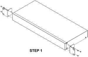
NOTE: The type of screw is flat head M3 x 5mm. - STEP 2: After attaching two brackets, line up the rack-mounting positions of the holes in the brackets with the appropriate holes on the rack and then fasten the Switch on the rack by using screws.
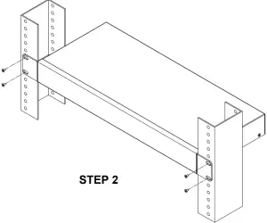
NOTE: The rack-mounting screws are not included in the package.
Web Interface: Connect & Login
- Factory default IP: 192.168.169.1
- Login with default account and password.
- Username: admin
- Password: admin
CLI Initialization and Configuration
- Key-in the command under Telnet: telnet 192.168.169.1
- Login with default account and password.
- Username: admin
- Password: admin
- Change the IP with commands listed below:
config
ip address xxx.xxx.xxx.xxx mask xxx.xxx.xxx.xxx
exit
NOTE
- •Please scan below QR Code to download online resources.
Download Link: https://www.proscend.com/en/product/850X.html