![]() DIS-700G-28SW
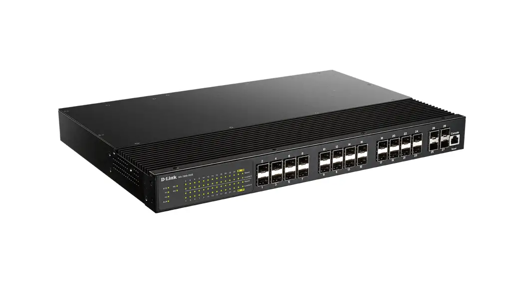
DIS-700G-28SW
Industrial Layer 2+ Gigabit Managed
Switch with SFP slots
Quick Installation Guide
This document outlines the quick installation of the DIS-700G-28SW series.
Package Checklist
Please verify that the box contains the following items:
| Item | Quantity |
| Rack-mounted Ethernet switch | 1 |
| Rack-mount bracket | 2 |
| Screws (for bracket) | 6 |
| ALM Terminal Block (2-pin) | 1 |
| Quick Installation Guide | 1 |
| RJ45 Ethernet Port Dust Cover | 14 |
| SFP Ethernet Port Dust Cover | 2 |
Safety Instructions
When a connector is removed during installation, testing, or servicing, or when an energized fiber is broken, a risk of ocular exposure to optical energy that may be potentially hazardous occurs, depending on the laser output power.
The primary hazards of exposure to laser radiation from an optical-fiber communication system are:
- Damage to the eye by accidental exposure to a beam emitted by a laser source.
- Damage to the eye from viewing a connector attached to a broken fiber or an energized fiber.
Model Layouts
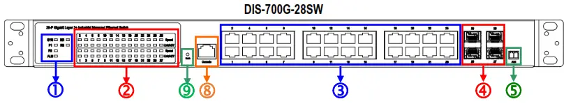
Front Access Models
Front View
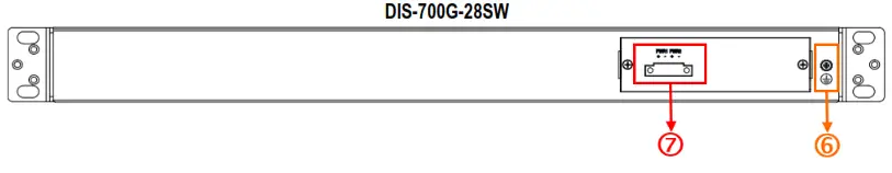
Rear View
| Item | Description |
| 1 | System Status Indicators (LED) |
| 2 | Port Status Indicators (LED) |
| 3 | Gigabit Copper RJ45 Ports |
| 4 | 100/1000BaseSFP Slot (Port 25 & 26) 1000BaseSFP Slot (Port 27 to 28) |
| 5 | Terminal Block for Alarm Relay output |
| 6 | Grounding Screw |
| 7 | DC terminal block (dual input) |
| 8 | Console Port |
| 9 | Reset Button |
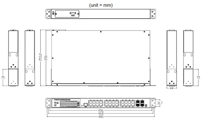
Dimensions
Rack Mounting
When mounting the switch, practice good safety habits. Relay rack mounting normally requires at least two people.
- Obtain the tools required for the mounting hardware.
- Attach the mounting brackets to the switch in one of two supported positions by using the screws in the accessory kit.

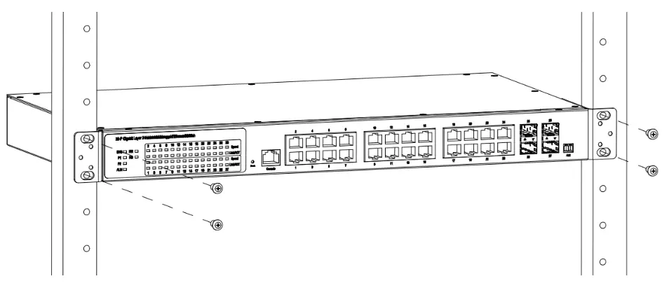
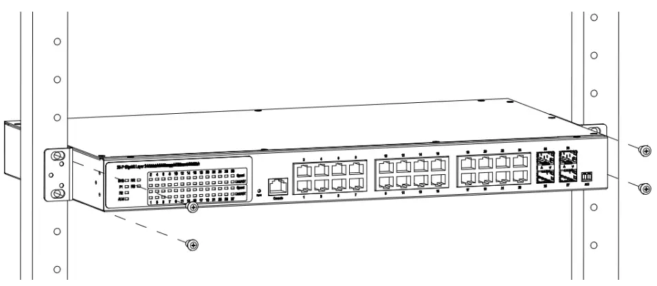
- From the front of the relay rack, position the switch in a preferred location.
- Secure the switch in place with the provided screws on both left and right sides of the mounting bracket.
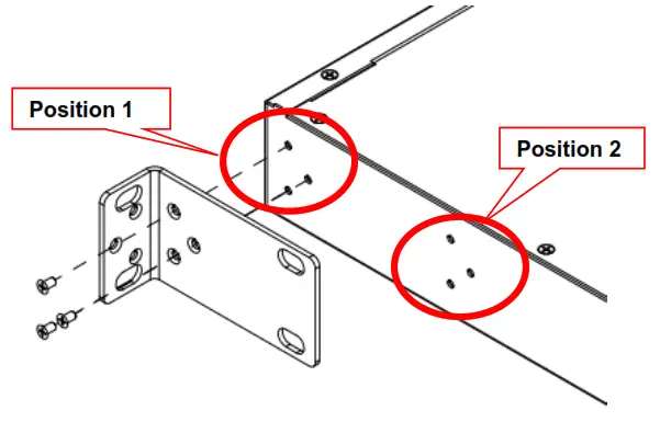
 Mounting Bracket Position 1 for Standard Mount
 Mounting Bracket Position 2 for Standard Mount
Ground Connecting
The switch must be properly grounded for optimum system performance.
Alarm Relay Connecting
The 30VDC/1A alarm relay output contacts are located in a 2P terminal block.
The alarm relay contact is “Normal Open”, and it will be closed when detected any power failures.
Power Connecting
AC Power Connection
If you use AC power, connect the AC power cord to the AC supply socket on the rear panel, and plug the cord into the external power source. The voltage must be 100 to 240 V (±10% tolerance).
Warning: Ensure that all power sources to the chassis (power distribution panel) are turned off during the connection.
Ethernet Interface Connecting (RJ45 Ethernet)
The switch provides two types of electrical (RJ45) and optical (mini-GBIC) interfaces.
Connecting the Ethernet interface via RJ45:
- To connect to a PC, use a straight-through or a cross-over Ethernet cable,
- To connect the switch to an Ethernet device, use UTP (Unshielded Twisted Pair) or STP (Shielded Twisted Pair) Ethernet cables.
Ethernet Interface Connecting (Fiber, SFP)
For a 1000 Mbps fiber port available, please use the mini-GBIC SFP. These accept plug-in fiber transceivers that typically have an LC-style connector.
For a 100 Mbps fiber port (ports 25 & 26 only) available, please prepare the LC connectors or SC connectors (with the use of an optional SC-to-LC adapter).
They are available with multimode, single mode, long-haul, or special-application transceivers.
DANGER: Never attempt to view optical connectors that might be emitting laser energy.
Do not power up the laser product without connecting the laser to the optical fiber and putting the cover in position, as laser outputs will emit infrared laser light at this point.
Console Connection
The Console port is for local management by using a terminal emulator or a computer with terminal emulation software.
- DB9 connector connect to the computer COM port
- Baud rate: 115200bps
- 8 data bits, 1 stop bit
- None Priority
- None flow control
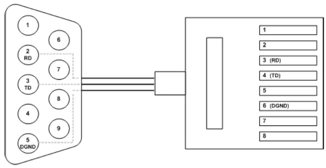
To connect the host PC to the console port, an RJ45 (male) connector-to-RS232 DB9 (female) connector cable is required. The RJ45 connector of the cable is connected to the CID port of DIS-700G-28SW; the DB9 connector of the cable is connected to the PC COM port. The pin assignment of the console cable is shown below:
Connect & log in to DIS-700G-28SW
- Connecting to DIS-700G-28SW Ethernet port (RJ45 Ethernet port).
- Factory default IP: 192.0.2.1
- Login with the default account and password.
Username: admin
Password: admin
CLI Initialization & Configuration (Optional)
- Connecting to DIS-700G-28SW Ethernet port (RJ45 Ethernet port).
- Enter the command: telnet 192.0.2.1
- Login with the default account and password.
Username: admin
Password: admin - Change the IP address with the commands listed below:
CLI Command:
enable configure interface VLAN 1
ip-address xxx.xxx.xxx.xxx netmask xxx.xxx.xxx.xxx exit
SYSTEM RESET
The Reset button is provided to reboot the system without the need to remove power. Under normal circumstances, you will not have to use it. However, or rare occasions, the DIS-700G-28SW may not respond; then you may need to push the Reset button.
LED STATUS INDICATIONS
| LED Name | Indicator /color | Condition |
| 1. System Status Indicators | ||
| SYS | On Green | The system is working normally |
| Flash Green | System booting, or database saving or remote download is in-progress | |
| Off | The system is not working or does not have supply power | |
| P1 | On Green | P1 power line has power |
| Flashing Green | P1 is DC power and only one pair of power is the input | |
| Off | P1 power line disconnect or does not have supply power | |
| P2 | On Green | P2 power line has power |
| Off | P2 power line disconnect or does not have supply power | |
| Alarm | On Red | Alarm event occurs |
| Off | No alarm | |
| RR (Ring Role) | On Green | One of the 3 Ring groups is enabled and is the Master role. |
| Off | The ring is a slave role | |
| RS (Ring Status) | On Green | Ring failure happens and detected |
| Off | No ring fail detected | |
| 2. Port Status Indicators | ||
| Copper port Link/Act (Port 1 to 24) | On Green | Ethernet link up but no traffic is detected |
| Flashing Green | Ethernet link up and there is traffic detected | |
| Off | Ethernet link down | |
| Copper port Speed (Port 1 to 24) | On Yellow | A 1000Mbps connection is detected |
| Off | No link or a 10 Mbps,100Mbps connection is detected | |
| SFP port Link (Port 25 to 28) | On Green | Ethernet link up |
| Flashing Green | Ethernet link up and there is traffic detected | |
| Off | Ethernet link down | |
| SFP Speed (100/1000M) (Port 25 to 28) | On | SFP port speed 1000Mbps |
| Off | SFP port speed 100Mbps or link down | |
Federal Communication Commission Interference Statement
Federal Communication Commission Interference Statement This equipment has been tested and found to comply with the limits for a Class A digital device, pursuant to part 15 of the FCC Rules. These limits are designed to provide reasonable protection against harmful interference when the equipment is operated in a commercial environment. This equipment generates, uses, and can radiate radio frequency energy and, if not installed and used in accordance with the instruction manual, may cause harmful interference to radio communications. Operation of this equipment in a residential area is likely to cause harmful interference in which case the user will be required to correct the interference at his own expense.
Non-modification Statement
Any changes or modifications not expressly approved by the party responsible for compliance could void the user’s authority to operate the equipment.
Caution
This device complies with Part 15 of the FCC Rules. Operation is subject to the following two conditions: (1) This device may not cause harmful interference, and (2) this device must accept any interference received, including interference that may cause undesired operation.
Innovation, Science and Economic Development Canada (ISED) Statement
This Class A digital apparatus complies with Canadian ICES-003. Cet appareil numérique de la classe A est conforme à la norme NMB-003 du Canada.
Japan Voluntary Control Council for Interference Statement
This is a Class A product based on the standard of the Voluntary Control Council for Interference (VCCI). If this equipment is used in a domestic environment, radio interference may occur, in which case the user may be required to take corrective actions.
CE EMI Class A Warning
This equipment is compliant with Class A of CISPR 32. In a residential environment, this equipment may cause radio interference.
Ver 1.01 (EU) 2019/12/16 GP801280X-000


