![]() Building Networks for people
Building Networks for people
DXS-1210-28T
24-port 10GBase-T and 4-port 25GBase-X SFP28 Managed Switch
Quick Installation Guide
Introduction
This Quick Installation Guide gives instructions for setting up the D-Link DXS-1210-28T switch. The model you have purchased may appear slightly different from those shown in the illustrations. For more detailed information about the switch, configuring the device, and technical specifications, please visit the website http://www.dlink.com/
Package Contents
Open the shipping carton of the Switch and carefully unpack its contents. Please consult the packing list located to make sure all items are present and undamaged.
- One DXS-1210-28T Switch
- AC power cord(s)
- AC power cord retainer
- One RJ-45 console cable
- Four rubber feet with adhesive backing
- 2 Mounting Brackets
- Mounting kit
- One Quick Installation Guide
If any of the above items are damaged or missing, please contact your local reseller for replacement.
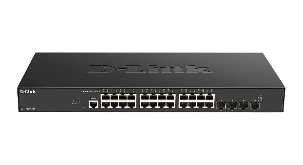
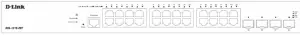
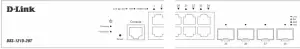
Hardware Overview
Front Panel Components
| Port | Description |
| Reset Button | • Press and hold for less than 5 seconds This reboots the Switch. All unsaved configurations will be lost. • Press and hold for between 5 and 10 seconds This resets the software configuration on the Switch to the factory default settings. All the port LEDs will light up amber for 2 seconds to indicate the start of the factory reset stage. |
| Console Port | The console port is used to connect to the CLI of the switch. The connection is out-of-band and the console cable (included in the package) must be used for the connection. |
| RJ45 Ports (1 to 24) | This switch is equipped with 24 10GBase-T ports. |
| SFP28 Ports (25 to 28) | This switch is equipped with 4 25GBase-X SFP28 ports, which support a wide collection of SFP+/WDM SFP+/SFP28 transceivers. |
LED Indicators
| LED | Colour | Status | Description |
| Power | Green | Solid | Power on. |
| Blinking | Performing system self-test. | ||
| Light Off | Power off. | ||
| Console | Green | Solid | Console session is active (user logged in). |
| Light Off | Console session is inactive (user logged out). | ||
| Fan Error | Red | Solid | Fan off (due to fan runtime failure). |
| Light Off | Normal operation (diagnostics test passed). | ||
| Link/Act (10GE RJ45 ports) | Green / Amber | Solid Green | Active connection at 10 Gbps through the port. |
| Blinking Green | Data is transmitted and received through the port. | ||
| Solid Amber | Active connection at 100/1000 Mbps through the port. | ||
| Blinking Amber | Data is transmitted and received through the port. | ||
| Light Off | Inactive connection or no link present. | ||
| Link/Act (25GE SFP28 ports) | Green / Amber | Solid Green | Active connection at 25 Gbps through the port. |
| Blinking Green | Data is transmitted and received through the port. | ||
| Solid Amber | Active connection at 10 Gbps through the port. | ||
| Blinking Amber | Data is transmitted and received through the port. | ||
| Light Off | Link down or no link. |
Rear Panel

| Port | Description |
| AC Power Connector | The AC power cord (included in the package) can be plugged into this receptacle to supply the switch with 100-240 VAC power at 50-60 Hz. |
| Power Cord Retainer Hole | The power cord retainer hole is used to insert the power cord retainer to secure the AC power cord. |
| Switch GND | Switch GND is used for connecting the grounding wire. |
| Security Lock | The Kensington-compatible security lock can be used to connect the Switch to a secure immovable device. Insert the lock into the notch and turn the key to secure the lock. The lock-and-cable apparatus should be purchased separately. |
Installation Guidelines
Installing the Switch without a Rack
When installing the switch on a desktop or shelf, the rubber feet included with the device must be attached on the bottom at each corner of the device’s base. Allow enough ventilation space between the device and the objects around it.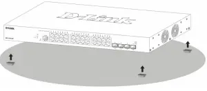
Installing the Switch in a Standard 19” Rack
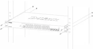
The Switch can be mounted in a standard 19″(1U) rack using the provided mounting brackets. Fasten the mounting brackets to the sides of the Switch using the screws provided.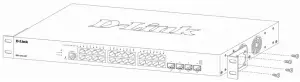
Fasten the mounting brackets in any available open space in the rack using the screws provided.
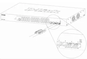
Installing Transceivers into the Transceiver Ports
The Switch is equipped with SFP28 ports, which supply connecting SFP+/WDM SFP+/ SFP28 transceivers.
 NOTE: The FEC function is not supported on the 25 Gbps SFP28 ports. If the 25 Gbps SFP28 connection between this switch and another non-DXS-1210 series switch is not working, the FEC function needs to be disabled on the remote switch.
FEC (Forward Error Correction) is the system of error correction by forestalling. It is applied to correct the mistakes while data transmitting by delivering reduntant information, which is used to recover the initial content of the message. The function is widely used at LANs and telecom networks.
Connecting to Power
Grounding the Switch
The following steps explain the procedure for connecting the switch to a protective ground:
- Verify if the system power is off.
- Using a screwdriver, tighten the ground screw to secure the ground cable to the switch.
- Attach the terminal lug ring at the other end of the grounding cable to an appropriate grounding source.
- Verify if the connections at the ground connector on the switch and the rack are securely attached.

Power On (AC Power)
Plug one end of the AC power cord into the power socket of the Switch and the other end into the local power source outlet.
Power Failure (AC Power)
For AC power supply units, as a precaution, in the event of a power failure, unplug the Switch. When power has resumed, plug the Switch back in. After the system is powered on, the Power LED will blink green to indicate that the system is booting up.
Installing the Power Cord Clip
А) With the rough side facing down, insert the Tie Wrap into the hole below the power socket.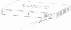
B) Plug the AC power cord into the power socket of the Switch.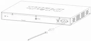
C) Slide the Retainer through the Tie Wrap until the end of the cord.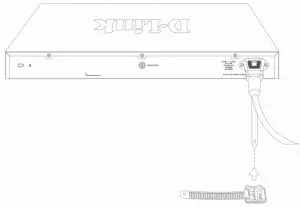
D) Circle the tie of the Retainer around the power cord and into the locker of the Retainer.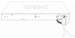
E) Fasten the tie of the Retainer until the power cord is secured.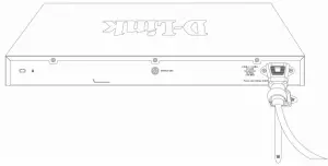
Switch Connections
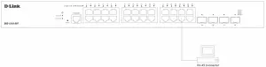
Switch to End Node
An end node is a generic name for edge networking devices that will be connected to this switch. Typical examples of end nodes are Personal Computers (PCs), Notebooks, Access Points, Print Servers, VoIP Phones and more. Each end node should be fitted with an RJ45 networking port. Normally, end nodes will connect to this switch by using a standard twisted-pair UTP/STP network cable. When a successful connection is established, the corresponding port light will illuminate and blink to indicate that network activity is taking place on that port.
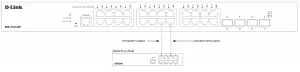
Switch to Another Switch
The Switch can be used to connect to any other switch or hub in the network. This network topology is used when the Switch does not have enough ports to cater for all the end nodes in the network. There is a great deal of flexibility on how connections are made using the appropriate cabling.
- Connect a 100Base-TX switch port to the Switch via a Category 5 UTP/STP cable.
- Connect a 1000Base-T switch port to the Switch via a Category 5e UTP/STP cable.
- Connect a 10GBase-T switch port to the Switch via a Category 6/6a/7 UTP/STP cable.
- Connect a fiber, uplink, switch port to the Switch’s SFP28 port via a fiber optical cable.
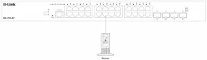
Connecting to Server
Management Options
Web-based Management Interface
After successfully installing the Switch, the user can configure the Switch, monitor the LED panel, and display statistics graphically using one of the Web browsers given below:
- Microsoft Internet Explorer
- Mozilla Firefox
- Safari
- Google Chrome.
To access the Web UI, open a standard web browser, enter the IP address of the Switch into the address bar of the browser, and press the Enter key.

NOTE: The default IP address of the switch is 10.90.90.90 (subnet mask 255.0.0.0).
In the authentication window, enter the User Name and Password and click the Login button to access the Web UI.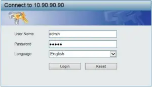
NOTE: The default username and password for the Web UI is admin.
SNMP-based Management
The Switch can be managed with an SNMP-compatible console program. The Switch supports SNMP version 1.0, version 2.0 and version 3.0.
Command Line Interface
The user can also connect a computer or terminal to the serial console port to access the Switch. The command line interface provides complete access to all Switch management features.
Connecting the Console Port
To use the console port, the following equipment is needed:
- A terminal or a computer with both an RS-232 serial port and the ability to emulate a terminal (it is possible to use PuTTY or Tera Term etc);
- A console cable with a male DB-9 connector on one end and an RJ-45 connection on the other. This cable should be included with the Switch.
To connect a terminal to the console port:
- Connect the male DB-9 connector on the console cable to the RS-232 serial port on the computer.
- Insert the RJ-45 connector into the RJ-45 console port on the front of the Switch. Set the terminal emulation software as follows:
- Serial port: COM port 1
- Baud rate: 115200
- Data bits: 8
- Parity: none
- Stop bits: 1
- Flow control: none
After the boot sequence completed, the CLI login screen is displayed.
NOTE: The default username and password for the CLI is admin.
First Time Connecting to the Switch
At the login screen, enter the Username and Password and press Enter after each entry to access the CLI.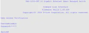 NOTE: For security reasons, it is highly recommended to configure a personal username and password for this Switch.
Additional Information
For more detailed information on how to set up and configure the access point, please visit the website http://www.dlink.com/