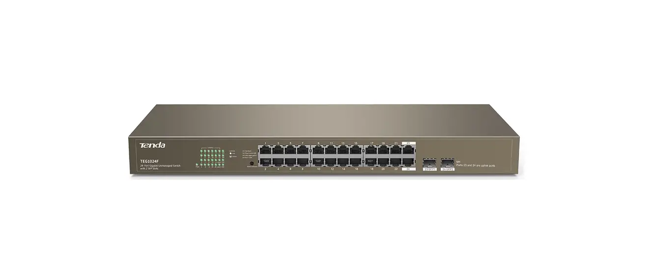
Tenda TEG1024F 24-Port Gigabit Unmanaged Switch with 2 SFP Slots

Package contents
- Switch * 1
- Power cable * 1
- Quick installation guide * 1
- Mounting hardware (Pad, screw, L-shaped bracket)
Connect devices
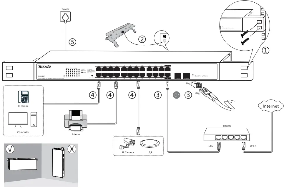
Note
- For safety, do not face the air vents of the switch down.
- All RJ45 ports of this switch support the Auto MDI/MDIX function, which ind icates that either straight cable or crossover cable
is acceptable when you connect your switch to Ethernet devices.
LED Indicators
| LED indicator | Status | Desc;ription |
| PWR | Solid on | The switch is connected to a power supply properly. |
| Off | The switch is disconnected from a power supply or not properly connected to a power supply. | |
|
Link/Act | Solid on | The port is connected properly. |
| Blinking | Data is being transmitted over the port. | |
| Off | The port is disconnected or improperly connected. | |
| Ml | Solid on | The switch is in Standard mode. |
| M2 | Solid on | The switch is in Flow Control Off mode. |
| M3 | Solid on | The switch is in Link Aggregation mode. |
| M4 | Solid on | The switch is in Port VLAN mode. |
| Port /Bun on | Description |
| 1-22 | They are downlink ports used to connect to devices such as compute rs, IP cameras. |
| 23-24 | They are uplink RJ45 ports used to connect to routers or aggregation switches. |
| 23/SFPl 24/ SFP2 | They are uplink SFP ports used to connec t to optical modules. 23/SFPl and RJ45 port 23 form acombo port;24/SFP2 and RJ45 port 24 form another combo port. When 23/SFP1 and 23 are connected, only 23/SFP1 takes effect. When 24/SFP2 and 24 are connected, only 24/SFP2 takes effect. |
| Mode Selection | Used to change the work mode of the switch. |
Work Mode Introduction
The switch can work In the Standard, Flow Control Off, Link Aggregation, or Port VLAN mode. The default mode Is Standard.
- M1: Standard mode. In this mode, the switch works as a common switch.
- M2: Flow Control Off mode. In this mode, flow control is disabled on all ports.
- M3: Link Aggregation mode. In this mode, ports 23 and 24form a static link aggregation group (LAG). Traffic is distributed between the two ports based on source and destination MAC addresses. When your switch works at the edge of a network and one of its uplink ports is used to connect to a central device, you are recommended to change the switch to this mode.
Note: When the switch is in Link Aggregation mode, the LA G’s connected ports on the peer device must support link aggregation function too. - M4: Por1VLAN mode. In this mode, ports 1 to 22 can communicate with uplink ports (ports 23 and 24) but cannot communicate with each other. You can use this mode to reduce broadcast storm and Isolate DHCP broadcast
Changing the Mode
After the switch ls powered on, press the Mode Salactlon button once to change the switch to the next mode. If you want to change your switch to the previous mode or to the one after the next mode, hold the Mode Selection button down till the LED indicator of your required mode lights green.
Tip: After you change the switch’s work mode, it takes 5 seconds for the switch to reboot automatically.
Specifications
| Standard | IEEE 802.3, IEEE B02.3u, IEEE8 02.3ab, IEEE 802.3x | |
| Port | 24 • 10/100/1OOOMbps RJ45 port 2 • SFP port(combo) | |
| LED Indicator | 24 • Link/Act, 1 * PWR 1 *Ml, 1*M2, 1 *M3, 1 *M4 | |
| AC Input | 100-2401/ AC, 50/6() Hz | |
|
Mode | Ml: Standard M2: Flow Control Off M3: Link Aggregation M4: Port VLAN | |
|
Transmission Rate | Ethernet: 10 Mbps (half duplex)/ 20 Mbps (full duplex) Fast Ethernet: 100 Mbps (half duplex)/ 200 Mbps (full duplex) Gigabit Ethernet: 2000 Mbps (full duplex) | |
|
Transmission Media | Ethernet: CAT3 UTP/STP cable or better Fast Ethernet: CATS UTP/STP cable or better Gigabit Ethernet: CAT5e or CAT6 UTP/STP cable (Recomm ended) 1OOOBase-SX: MMF (Multimode fiber) 1OOOBase-L X: MMF (Multimode fiber) or SMF (Sing le-mode fiber) | |
| Transmission Method | Store- and-forward | |
| Switching Capacity | 4B Gbps | |
| Mac Address Entities | Auto learning & auto aging Ma ximum MAC address: 8 K | |
| Lightning Protection for RJ45 Ports | 6kV | |
| Lightning Protection for Power Port | Common mode: 6 kV Differential mode: 4 kV | |
| Dimensions | 440 mm* 178.8 mm *44 mm | |
|
Operating Environment | Temperature | o•c- 45°C |
| Humidity | (10% – 90%) RH non-condensing | |
|
Storage Environment | Temperature | -40″C- 7r:f’C |
| Humidity | (5%- 90%) RH, non •condensing | |
CE Mark Warning
- This is a Class A product. In a domestic environment, this product may cause radio interference, in which case the user may be required to take adequate measures.
- The mains plug is used as disconnect device, the disconnect device shall remain readily operable.
NOTE:- The manufacturer is not responsible for any radio or TV interference caused by unauthorized modifications to this equipment.
- To avoid unnecessary radiation interference, it is recommended to use a shielded RJ45 cable.
FCC Statement
- This equipment has been tested and found to comply with the limits for a Class A digital device, pursuant to Part 15 of the FCC Rules. These limits are designed to provide reasonable protection against harmful interference when the equipment is operated in a commercial environment. This equipment generates, uses, and can radiate radio frequency energy and, if not installed and used in accordance with the instruction manual, may cause harmful interference to radio communications. Operation of this equipment in a residential area is likely to cause harmful interference in which case the user will be required to correct the interference at his own expense.
- This device complies with Part 15 of the FCC Rules. Operation is subject to the following two conditions: (1) this device may not cause harmful interference, and (2) this device must accept any interference received, including interference that may cause undesired operation.
Caution!
Any changes or modifications not expressly approved by the party responsible for compliance could void the user’s authority to operate the equipment.
NOTE:- The manufacturer is not responsible for any radio or TV interference caused by unauthorized modifications to this equipment.
- To avoid unnecessary radiation interference, it is recommended to use a shielded RJ45 cable.
RECYCLING
This product bears the selective sorting symbol for Waste electrical and electronic equipment (WEEE). This means that this product must be handled pursuant to European directive 2012/19/EU in order to be recycled or dismantled to minimize its impact on the environment.
User has the choice to give his product to a competent recycling organization or to the retailer when he buys a new electrical or electronic equipment.
Safety Precautions
Before performing an operation, read the operation instructions and precautions to be taken, and follow them to prevent accidents. The warning and danger Items in other documents do not cover all the safety precautions that must be followed. They are only supplementary information, the installation and maintenance personnel need to understand the basic safety precautions to be taken.
- Do not use this apparatus near water.
- Clean only with dry cloth.
- Do not block any ventilation openings, such as newspapers, table-cloth, curtains, etc.
- Do not install near any heat sources such as radiators, heat registers, stove or other apparatus that produce heat.
- Do not damage the ground conductor or operate the device in the absence of well installed ground conductor. Conduct the appropriate electrical inspection.
- Protect the power code from being walked on or pinched particularly at the plugs, convenience receptacles and at the point where they exist form the apparatus.
- Only use attachments/accessories specified by the manufacturer.
- Unplug this apparatus during lightning storms or when unused for a long periods of time.
- Mains plugs is used as the disconnect device, the disconnect device shall remain readily operable.
- Refer all servicing to qualified service personnel. Servicing is required when the apparatus has been damaged In any way, such as power-supply cord or plug Is damaged, llquld has been spllled or objects have fallen into the apparatus, the apparatus has been exposed to rain or moisture, does not operate normally, or has been dropped.
- Warning:To reduce the risk of fire or electric shock, do not expose this apparatus to rain or moisture.
The apparatus shall not been exposed to dripping or slashing. - Warning:To reduce the risk of electric shock, do not remove cover as there no user-serviceable parts inside. Refer servicing to qualified personnel.
Copyright
- Copyright e 201 8 Shenzhen Tenda Technology Co., Ltd. All rights reserved.
- Tenda is a registered trademark legally held by Shenzhen Tenda Technology Co., Ltd. Other brand and product names mentioned herein are trademarks or registered trademarks of their respective holders. Specifications are subject to change without notice.
Technical Support
- Shenzhen Tenda Technology Co., Ltd.
- 6-8 Floor, Tower E3, N0.1001, Zhongshanyuan Road, Nanshan District, Shenzhen, China. 51 8052
- USA hotline: 1 -800-570-5892
- Toll Free: Daily 9am to 6pm EST
- Canada hotline: 1 -888-998-8966
- Toll Free: Mon to Fri, 9am to 6pm PST
- Website: http://www.tendaus.com
- Email: [email protected]
- Hong Kong Hotline: 00852-8193 1 998
- Website: http://www.tendacn.com
- E-mail: [email protected]


