PROSCEND 850G-10PWI Industrial Ethernet Switch Installation Guide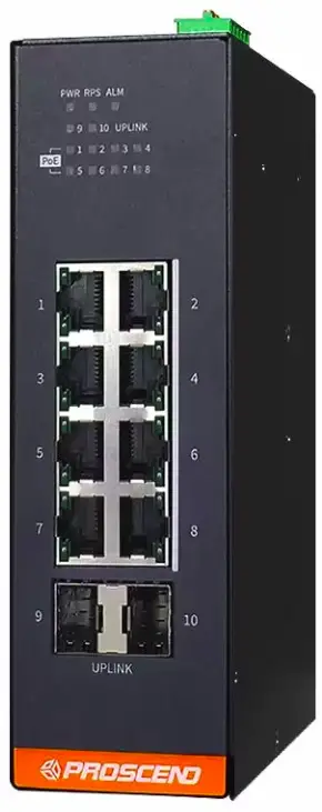
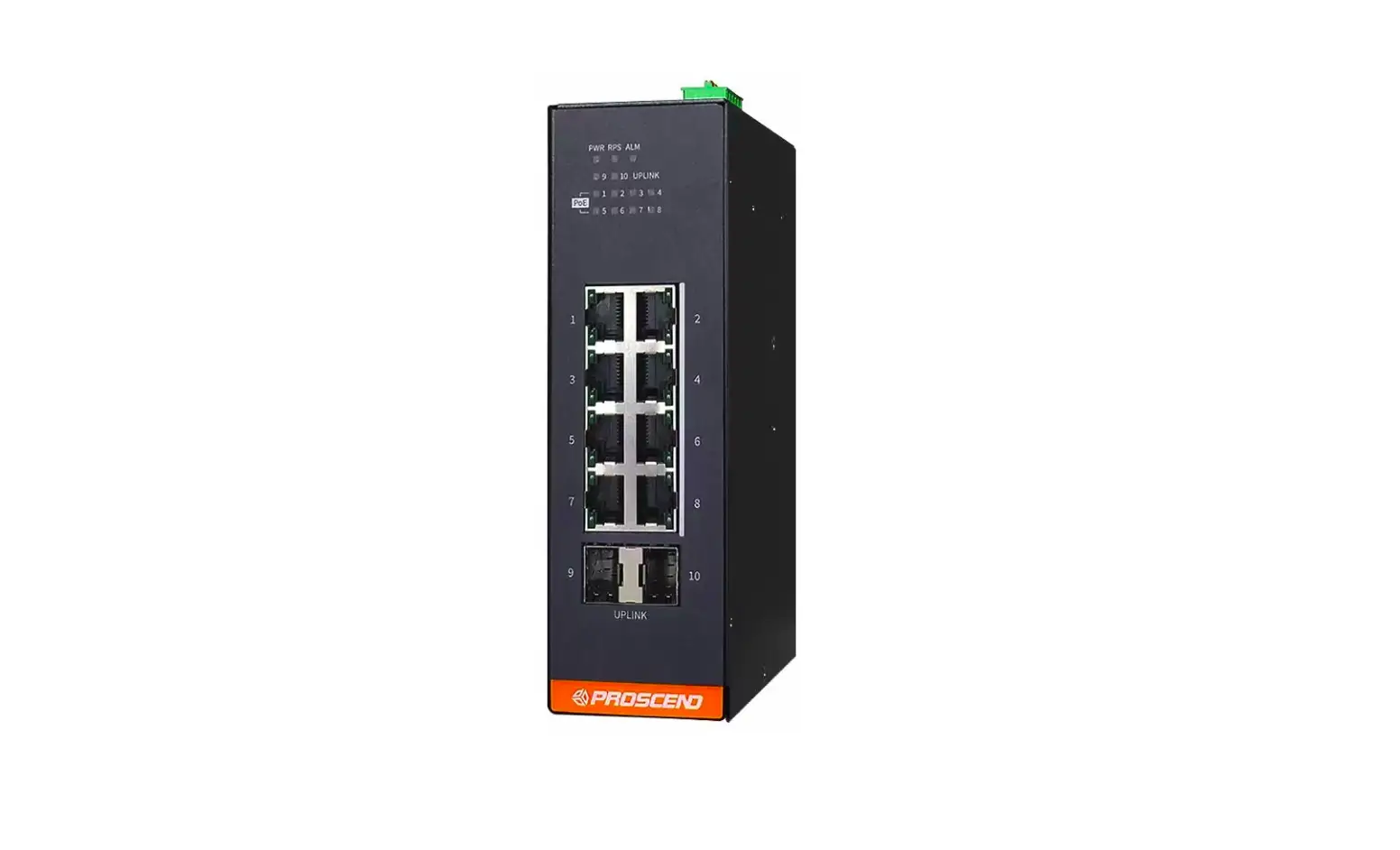
850G-10PWI Industrial Ethernet Switch
Connecting Power
The 850G-10PWI Industrial Ethernet Switch can be powered from two power supplies (input range 24~57 VDC). Two power supplies are on the top panel of the switch. Insert the positive and negative wires (AWG 12-24) into V+ and V- contacts on the terminal block respectively and use a flathead screwdriver to push in and open the wire clamp.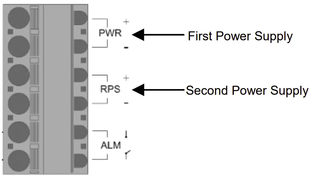
![]() WARNING
WARNING
The DC power should be connected to a well-fused power supply.
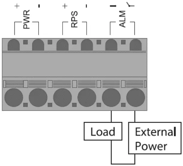
Alarm Relay and Ground
- The alarm relay output contacts are shown as ALM next to the DC terminal block connector as the figure below.
- The alarm relay out is “Normal Open”, and it will be closed when it is detecting any predefined failure such as power failures.
- The relay output with current carrying capacity of 1A @ 24 VDC.
- The switch must be properly grounded for optimum system performance
Ground Connector
DIP Switch Setting
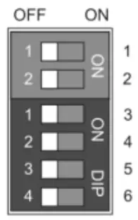
| DIP | Function Description |
| 1 (PWR)2 (RPS) | ON: Power alarm reporting is enabled. OFF: Power alarm reporting is disabled. |
| 3 (Storm) | ON: Broadcast storm control is enabled.OFF: Broadcast storm control is disabled. |
| 4 (QoS) | ON: Port Priority is enabled on Port 2.OFF: Port Priority is disabled. |
| 5 (Port 9)6 (Port 10) | ON: Port 100FX support is enabled. OFF: Port 100FX support is disabled. |
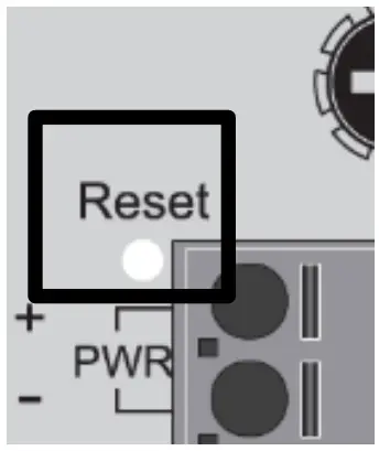
LED Indicators
| Function | Operation |
| Reboot | Press the Reset button for 2 secondsand release. |
| Reset to factory default | Press the Reset button for 10 seconds and release. |
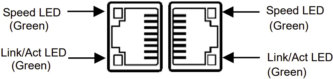
LED Indicators
| LED | Color | Description |
| PWR/RPS | On: Green | PWR/RPS is powered. |
| Off | PWR/RPS is not powered. | |
| ALM | On: Red | Alarm for abnormal power status or function. |
| Off | Normal operation or DIP switch OFF. | |
| RJ45 LAN port Link/Act | On: Green | Ethernet LINK UP. |
| Blinking:Green | Ethernet traffic detected. | |
| Off | Ethernet LINK DOWN. | |
| RJ45 LAN port Speed | On: Green | Ethernet LINK UP at 1000Mbps. |
| Off | Ethernet LINK DOWN or LINK UP at10Mbps/100Mbps | |
| UPLINK | On: Green | LINK UP. |
| Blinking: Green | Traffic detected. | |
| Off | LINK DOWN. | |
| PoE | On: Green | PoE PD (Powered Device) connected. |
| Off | PoE PD (Powered Device) disconnected. |
RJ45 Connector Pinouts
The pin assignment of RJ45 connector is shown in the following table.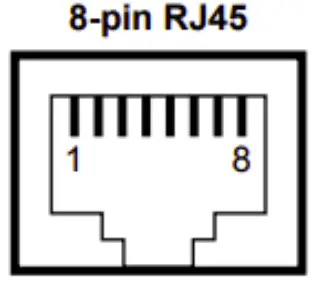
| Pin | Description | PoE Pinouts |
| 1,2 | T/Rx+, T/Rx- | V+ |
| 3,6 | T/Rx+, T/Rx- | V- |
| 4,5 | T/Rx+, T/Rx- | X |
| 7,8 | T/Rx+, T/Rx- | X |
DIN-rail Mounting
STEP 1: Use the screws to install the DIN-rail kit to attach at the rear side of the switch.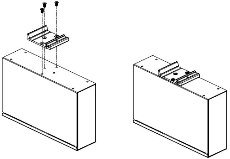
STEP 2: Hook the unit onto the DIN-rail.
STEP 3: Push the bottom of the unit towards the DIN-rail until it locks in place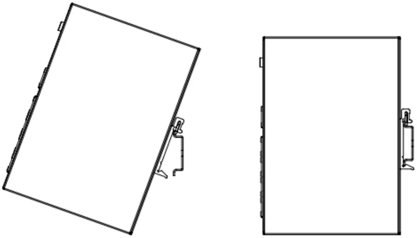
Web Interface: Connect & Login
- Factory default IP: 192.0.2.1
- Login with default account and password.
Username: root
Password: 2wsx#EDC
NOTE
Please scan below QR Code to download online resources.
Download Link:
https://www.proscend.com/en/product/850G-10PWI.html

Prescind Communications Inc. All rights reserved

References
 PROSCEND is a leading global provider of mission-critical Internet of Things (IoT) connectivity products, services, and solutions with high levels of reliability and security.
-
PROSCEND is a leading global provider of mission-critical Internet of Things (IoT) connectivity products, services, and solutions with high levels of reliability and security.
-
Industrial 10-Port GbE Managed PoE Switch | Industrial 5G Cellular Router Manufacturer | PROSCEND


