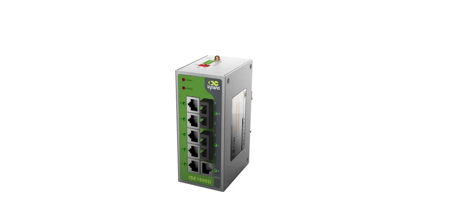
InHand ISE-P Industrial Ethernet Switch
ISE – P Industrial Ethernet Switch Quick Guide
www.Inhandnetworks.com 2022 Aug
Product Information
This document provides instructions for rapid deployment of the ISE Switch in the field. Before beginning, please carefully check the contents of the package for any missing or damaged parts. If there are any problems, please contact the InHand sales staff. InHand also offers optional accessories to customers depending on site characteristics and customer requirements. Please see the list of optional accessories below:
Standard Accessories
| Quantity | Description |
|---|---|
| 1 | Industrial Ethernet Switch |
| 1 | Install in Switch A Black elbow shaped power plug |
| 1 | 2-pin power terminal |
Features
- Input Voltage: 12/24/48VDC & 24VAC Class 2
- Power Consumption: [no value provided]
Product Usage Instructions
- Check the package contents and look for any missing or damaged parts.
- If there are any problems, contact the InHand sales staff.
- Connect the 2-pin power terminal to the switch.
- Install the switch using the provided black elbow-shaped power plug.
- Ensure the input voltage is 12/24/48VDC & 24VAC Class 2.
Information
This document instructs users on how to rapidly deploy the ISE Switch in the field.
Before beginning, check that you have:
- Small flat-head screwdriver
- Normal Philips-head screwdriver
Carefully check the contents of the package and look for any missing or damaged parts. If there are any problems, please contact the InHand sales staff. InHand also offers optional accessories to customers depending on the site characteristics and customer requirements please see the list of optional accessories below:
Standard Accessories
| Accessories | Quantity | Description |
| ISE – P Switch | 1 | Industrial Ethernet Switch |
| DIN-Rail | 1 | Install in Switch |
| 2-pin power terminal | 1 | A Black elbow shaped power plug |
Features
- Input Voltage:
12/24/48VDC & 24VAC Class 2 - Power Consumption:
<5W - Size:
- 24mm (W) x 100mm (H) x 61.8mm (D)
- (3 or 5 Ports Model)
- 40mm (W) x 100mm (H) x 61.8mm (D)
- (8 Ports Model)
- Weight:
- <0.16KG (3 or 5 Ports Model)
- <0.23KG (8 Ports Model)
- Operating Temperature:
-40℃~75℃ - Humidity:
5%~95%, No Condensation
Installation
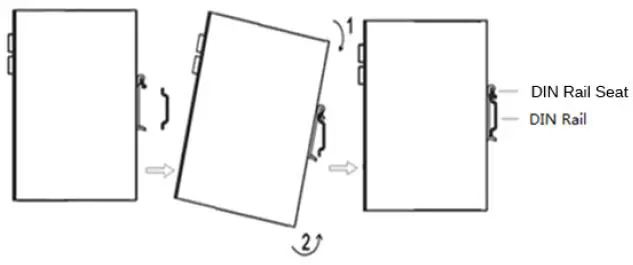
DIN rail mounting
Mount the Switch onto a DIN-rail
- Fixed to the back of the Switch is a DIN rail mounting bracket. To mount the Switch follow these steps:
- Hook the top seat of the mounting bracket onto the DIN rail.
- Push the bottom of the Switch towards the DIN rail, causing the bottom lip to snap onto the bottom of the rail. This may require some force.

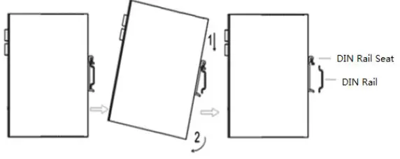
Uninstall the ISE from a DIN Rail
Removing the ISE is the opposite of mounting it.
- Pull the bottom part of the Switch out until the bottom lip of the bracket unclips from the rail. This may take some force.
- Lift the Switch so that the rail seat clears the top part of the DIN rail. Now, you are finished.

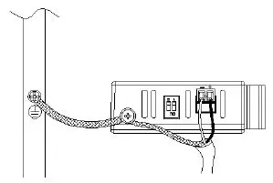
Power Connection Diagram
AC/DC input cable connection diagram for 3 or 5 Ports Model
AC/DC input cable connection diagram for 8 Ports Model
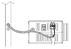
Before connecting the device to the AC/DC power inputs, make sure the AC/DC power source voltage is stable.
- L/+ end is connected to the positive AC/DC wire.
- N/- end is connected to the negative AC/DC wire.
In order to improve radiation protection and ESD resistance, equipment must be grounded. The grounding method will vary from site to site.
DIP Switch Setting
The switch allows users to enable or disable the Quality of Service (QoS) function and broadcast storm protection (BSP) with a DIP switch on the outer panel.
Settings for the Fast Ethernet switches:
| DIP Switch | Setting | Description | ||||
| Quality of Service(QoS) | ON | Enable the quality of Service to handle packet priorities in two WRR queues. QoS and priority mapping matrix in each queue. | ||||
| Qos 3bit priority | 7.6.5.4 | 3.2.1.0 | ||||
| Queues | 1 | 0 | ||||
| WRR | 16 | 1 | ||||
| OFF | Disables the Quality of Service | |||||
| Broadcast Storm Protection | ON | Enables broadcast storm protection (only allows a maximum of 200 broadcast packets per second) for each Ethernet port. | ||||
| OFF | Disable the broadcast storm protection. | |||||
Settings for the Gigabit Ethernet switch:
| DIP Switch | Setting | Description | ||||||
| Quality of Service(QoS) | ON | Enable the quality of Service to handle packet priorities in four WRR queues. QoS and ToS/DSCP priority mapping matrix in each queue. | ||||||
| CoS Priority | 7,6 | 5,4 | 3,2 | 1,0 | ||||
| ToS/DSCP Priority | 63 to 48 | 47 to 32 | 31 to 16 | 15 to 0 | ||||
| Queues | 3 | 2 | 1 | 0 | ||||
| WRR | 8 | 4 | 2 | 1 | ||||
| OFF | Disables the Quality of Service | |||||||
| Broadcast Storm Protection | ON | Enables broadcast storm protection (at a maximum of 2000 broadcast packets per second) for each Ethernet port. | ||||||
| OFF | Disable the broadcast storm protection. | |||||||
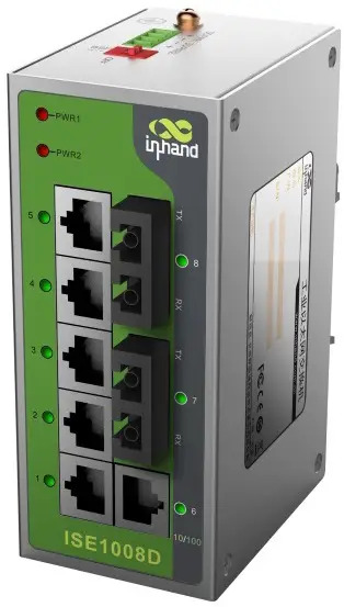
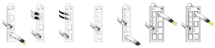
Port Connection Diagram
The LED Array
| LED | State | Description | |
| Power(PWR) | Green | On | Power is being supplied to power input. |
| Off | Power is not being supplied to power input. | ||
|
Ports (Full 1000M) | Green | On | When the port is active and links on 1000 Mbps. |
| Blinking | When the port’s data is being transmitted at 1000 Mbps. | ||
| Off | When the port is inactive or link down. | ||
| Amber | On | When the port is active and links on 100 Mbps. | |
| Blinking | When the port’s data is being transmitted at 100 Mbps. | ||
| Off | When the port is inactive or link down. | ||
| Ports (Full 100M) | Green | On | When the port is active and links on 100 Mbps. |
| Blinking | When the port’s data is being transmitted at 100 Mbps. | ||
| Off | When the port is inactive or link down. | ||


