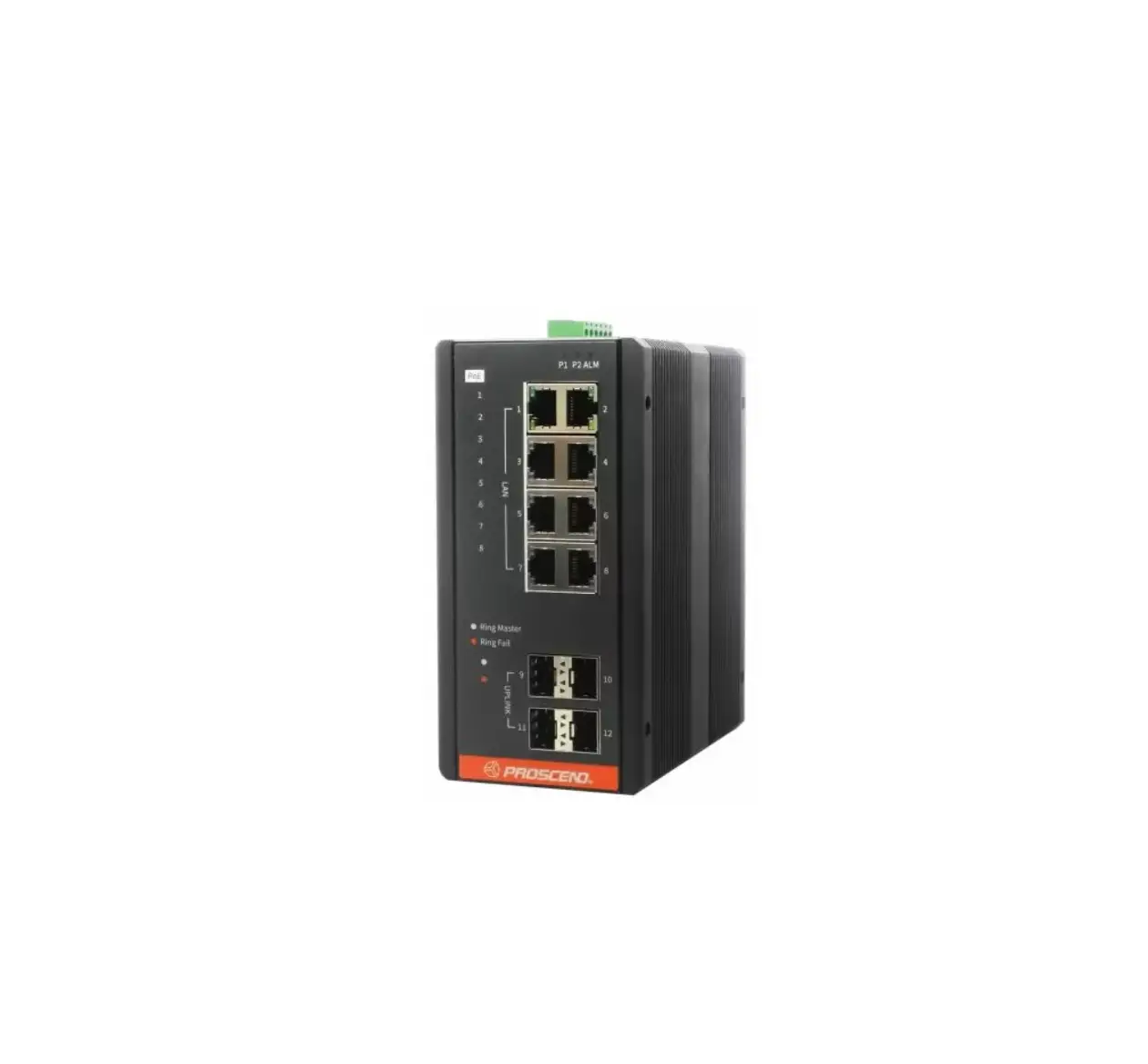
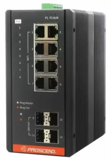
PROSCEND 850G-12PI Industrial Ethernet Switches
Connecting Power
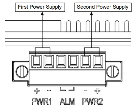
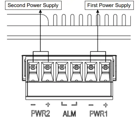
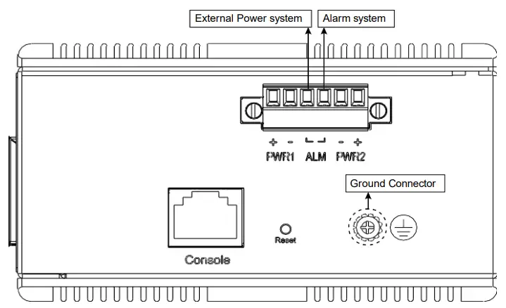
The 850G Series Industrial Ethernet Switch can be powered from two power supplies (input range 12 ~ 58 VDC for non-PoE Series, 54 ~ 58 VDC for PoE Series). Two power supplies are on the top panel of the switch. Insert the positive and negative wires (AWG 14-26) into V+ and V- contacts on the terminal block respectively and tighten the wire-clamp screws to prevent the wires from being loosened.
- Non-PoE Series
- PoE Series
![]() WARNING
WARNING
The DC power should be connected to a well-fused power supply.
Alarm Relay and Ground
- The alarm relay output contacts are in the middle of the DC terminal block connector as shown in the figure below.
- The alarm relay out is “Normal Open”, and it will be closed when it is detecting any predefined failure such as power failures or Ethernet link failures.
- The relay output with current carrying capacity of 0.5A @ 24 VDC.
- The switch must be properly grounded for optimum system performance.
LED Indicators
| LED | Color | Description |
| P1/P2 | On: Green | P1/P2 power line connected or power supplied |
| Off | P1/P2 power line disconnected or no power supplied | |
| ALM (Alarm) | On: Red | Ethernet link failure or power failure |
| Off | No Ethernet link failure and no power failure | |
| RJ45 LAN port Link/Act | On: Green | Ethernet LINK UP |
| Blinking: Green | Ethernet traffic detected | |
| Off | Ethernet LINK DOWN | |
| RJ45 LAN port Speed | On: Yellow | Ethernet LINK UP at 1000Mbps |
| Off | Ethernet LINK DOWN or LINK UP at 10Mbps/100Mbps | |
| SFP Uplink port Link/Act | On: Green | Ethernet LINK UP |
| Off | Ethernet LINK DOWN | |
| SFP Uplink port Speed | On: Yellow | Ethernet LINK UP at 1000Mbps |
| Off | Ethernet LINK DOWN or LINK UP at 100Mbps | |
| PoE Series only | ||
| Ring Master | On: Green | Ring Master enabled |
| Off | Ring Slave enabled | |
| Ring Fail | On: Green | Ring failure detected |
| Off | No Ring failure detected | |
| PoE | On: Yellow | PoE PD (Powered Device) connected |
| Off | PoE PD (Powered Device) disconnected | |
RJ45 Connector Pinouts
The pin assignment of RJ45 connector is shown in the following table.
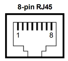
| Pin | Description | PoE Pinouts (PoE models only) |
| 1,2 | T/Rx+,T/Rx- | V+ |
| 3,6 | T/Rx+,T/Rx- | V- |
| 4,5 | T/Rx+,T/Rx- | X |
| 7,8 | T/Rx+,T/Rx- | X |
Console Connection
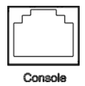
The console port on the top panel is for local management by using a terminal emulator or a computer with terminal emulation software.
- DB9 connector connect to computer COM port
- Baud rate: 115200bps
- 8 data bits, 1 stop bit
- None Priority
- None flow control
To connect the host PC to the console port, a RJ45 (male)
connector-to-RS232 DB9 (female) connector cable is used (not included in package). The RJ45 connector of the cable is connected to the console port of the switch; the DB9 connector of the cable is connected to the PC COM port. The pin assignment of the console cable is shown below: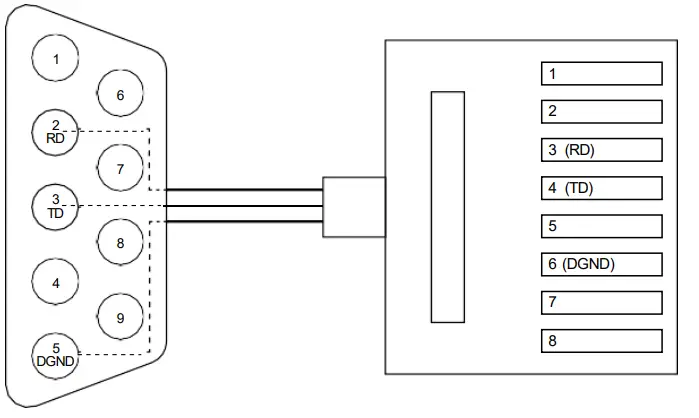
DIN-rail Mounting
STEP 1: Use the screws to install the DIN-rail kit to attach at the rear side of the switch.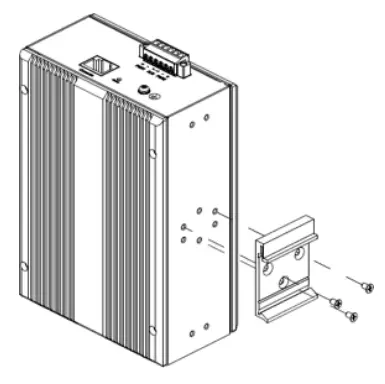
STEP 2: Hook the unit onto the DIN-rail.
STEP 3: Push the bottom of the unit towards the DIN-rail until it locks in place.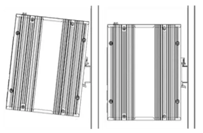
NOTE: For all switches (Non-PoE Series, PoE Series), the operation of DIN-rail mounting is the same.
Wall Mounting
Use the screws to install the wall-mounting kit to attach at the rear side of the switch.
NOTE: For all switches (Non-PoE Series, PoE Series), the operation of wall mounting is the same.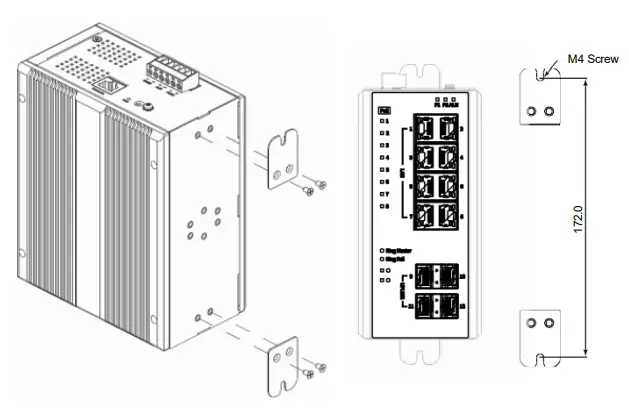
Web Interface: Connect & Login
- Factory default IP: 192.0.2.1
- Login with default account and password.
Username: admin
Password: (none)
CLI Initialization and Configuration
- Key-in the command under Telnet: telnet 192.0.2.1
- Login with default account and password.
Username: admin
Password: (none) - Change the IP with commands listed below
| enable configure terminal interface vlan 1 ip address xxx.xxx.xxx.xxx xxx.xxx.xxx.xxx exit |
NOTE
Please scan below QR Code to download online resources.
Download Link:
- https://www.proscend.com/en/product/850G-12PI.html
- https://www.proscend.com/en/product/850G-14I.html
- https://www.proscend.com/en/product/850G-12I.html
 |  |  |
| 850G-12PI | 850G-14I | 850G-12I |