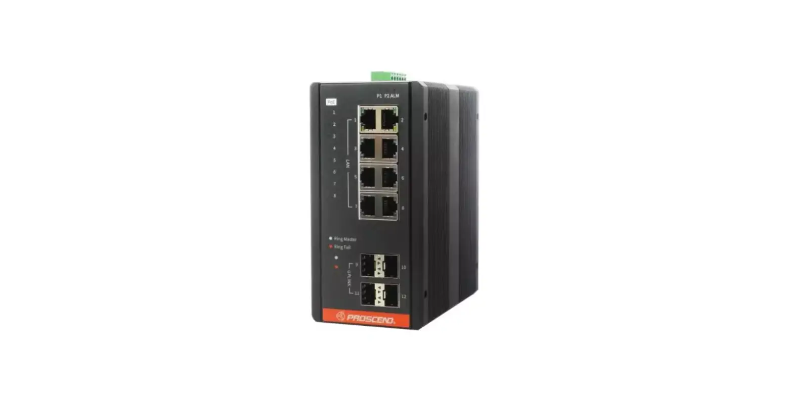
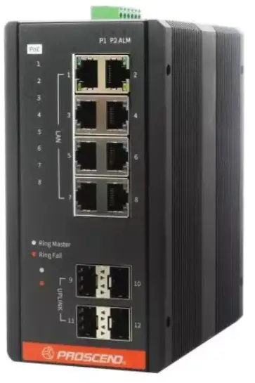
PROSCEND 810G-5PI Industrial GbE Unmanaged PoE Switch
Connecting Power
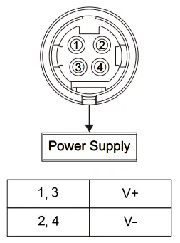
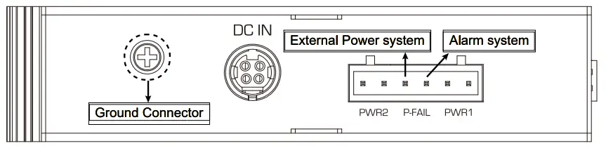
The 810G-5PI can be powered by two ways, one is directly connected to 4-pin DC IN power-connector, the other way is to insert the positive and negative wires (AWG 14-26) into V+ and V- contact on the terminal block respectively and tighten the wire-clamp screws to prevent the wires from being loosened. The input rage is 48~55 VDC.
4-pin DC IN power-connector
DC Terminal Block
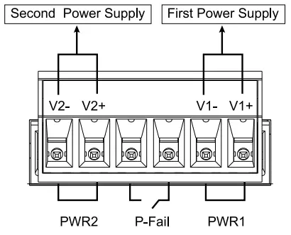
Alarm Rely and Ground
- The alarm relay output contacts are in the middle of the DC terminal block connector as shown in the figure below.
- The alarm relay out is “Normal Open”, and it will be closed when either one of PWR1 or PWR2 is not connected to power supply.
- The relay output with current carrying capacity of 0.25A @ 50 VDC.
- The switch must be properly grounded for optimum system performance.

PWR1 PWR2 DC IN Relay Alarm Detected Detected N/A Open Off Not Detected Detected N/A Close On Detected Not Detected N/A Close On Not Detected Not Detected N/A Close On
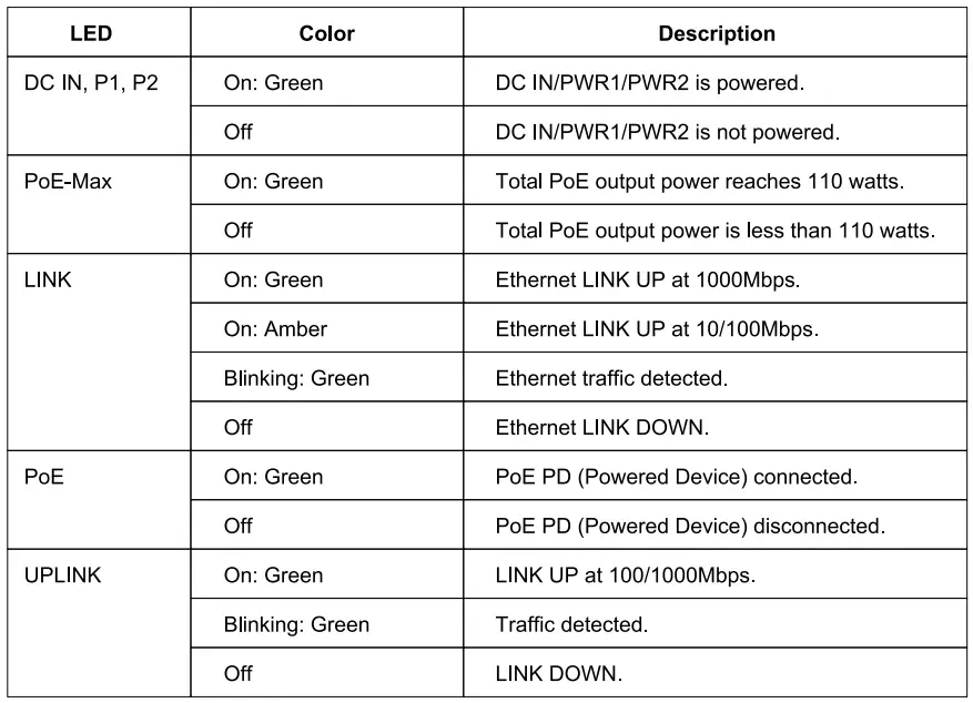
LED Indicators
RJ45 Connector Pinouts
The pin assignment of RJ45 connector is shown in the following table.
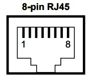
| Pin | Description | PoE Pinouts |
| 1,2 | T/Rx+, T/Rx- | V+ |
| 3,6 | T/Rx+, T/Rx- | V− |
| 4,5 | T/Rx+, T/Rx- | X |
| 7,8 | T/Rx+, T/Rx- | X |
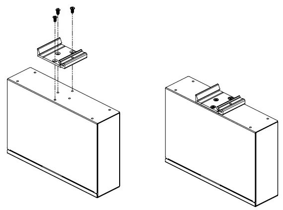
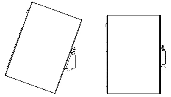
DIN-rail Mounting
- STEP 1: Use the screws to install the DIN-rail kit to attach at the rear side of the switch.

- STEP 2: Hook the unit onto the DIN-rail.
- STEP 3: Push the bottom of the unit towards the DIN-rail until it locks in place.

NOTE
- Please scan below QR Code to download online resources.
- Download Link: https://www.proscend.com/en/product/810G.html