
![]()
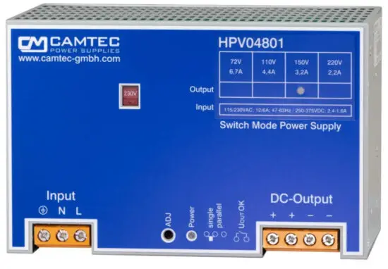
HPV04801 480W Industrial Power Supply
Instructions
Specification:
- C/V curve down to 0V, no foldback
- Power Good Relay AC & DC-ok optional
- Efficiency up to 93%
- Hold up time >50ms
- Soft start & auto-recovery
- Precise dynamic response to load change
- Designed for long life under full stress
- Strong input filters
- High reliability, shock & vibration proof
- EMC meets CE norm class B
- Overload and short circuit protection
- Large terminals 4x AWG20 – AWG6 (0,5 – 16mm²)
| Models | Voltage | Voltage setting | Current |
| HPV04801.072 | 72Vdc | 58 – 86Vdc | 6,7A |
| HPV04801.110 | 110Vdc | 86 – 132Vdc | 4,4A |
| HPV04801.150 | 150Vdc | 132 – 180Vdc | 3,2A |
| HPV04801.220 | 220Vdc | 180 – 240Vdc | 2,2A |
![]()
Technical Concept
The Camtec HPV series is a high precision switch mode power supply for an upscale demand. It is engineered and manufactured by CAMTEC in Germany. The design meets challenging applications like complex dc drives,piezo print heads, test stands, and professional machine-building. The power supply provides a low ripple noise, precise load regulation, and high efficiency of up to 93%. High-end long-life capacitors guarantee an extended hold-up time and an extraordinary lifetime of the power supply. The circuit design starts complex loads easily. The internal control circuit manages illegal operating conditions to prevent your system from being damaged. The HPV series features active high input transients with suppressor diodes, X2-capacitors, and varistors. All inputs, outputs, and feature connections are galvanic isolated. The design rules set values on extended interference immunity and safety.
The unit is designed in accordance with the EN61010-1, EN61010-2-201, EN62368-1, EN60950-1, and the EMC compatibility with EN55032.
Features
Design Conception
The HPV power supply series realizes very high power efficiency in space-saving housing. The latest generation electrical devices relate to the high reliability of all CAMTEC products. The CAMTEC philosophy is, to employ 125°C low ESR ultra long-life capacitors was expedient to achieve a superior life of the product. The HPV power supply is made for high reliability and demanding industrial applications, railway, infrastructure, professional machine building, printing machines, and complex dc-drive up
to precision piezo drives.
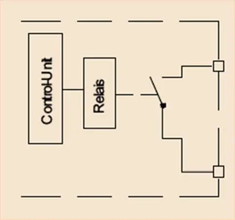
DC-ok Power Good Relay
The PG Relay connection indicates over-temperature, low DC voltage at the output, and low AC supply voltage at the input.
Galvanic Isolation
The power supply is galvanic isolated between the input and the output. All features like the Power Good Relay are connected to the DC power outputs.
Thermal shutdown
The HPV is featured with a thermal overload shut down and auto-recovery behavior.
Over Voltage Protection
Ticker mode and auto-recovery
Short Circuit Protection
A continuous short circuit does not cause damage to the power supply. The HPV delivers constant current and 0 output voltage. It recovers automatically after the short circuit is released.
Open Circuit Protection
The HPV series is continuously open circuit protected. The device delivers a stable output voltage and no current. If a load is immediately connected to the device, the power supply stabilizes within 1ms. It does not overshoot the output voltage.
Power Up Ramp
The devices have a soft start ramp when powering up. The device does not either overshoot the voltage or does the output flutter – independent if the load is connected or not.
Current Voltage Chart, CV & CC mode
The HPV series provides a perfect current-voltage chart. It has no foldback or other abnormalities. The output voltage can drop down to zero volts when the power supply is overloaded. The unit delivers a stable and constant current to the outputs.

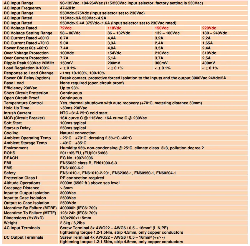
Technical Data Table
Manual and Technical Details
Technical Data Table – Power Connection & Voltage Setting
| Feature | Technology | Details and Connections | Section | Isolation |
| Potentiometer Voltage | 1 turn | High precision | U adj | 3000Vac to input & output |
| Power Good Relay | “b” contact | AWG24 – AWG14 / 0,25 – 2,5mm² | DC-ok | 3000Vac to input & output |
DC Voltage setting range
| Rated DC Voltage | 72Vdc | 110Vdc | 150Vdc | 220Vdc |
| Rated DC Current | 6,7A | 4,4A | 3,2A | 2,2A |
| DC Voltage Setting Range | 58 – 86Vdc | 86 – 132Vdc | 132 – 180Vdc | 180 – 240Vdc |
The DC voltage can be adjusted with a precision 1 turn potentiometer with low-temperature fading. The factory setting is to the rated voltage from the table above.
Optional DC-OK Relay (PG-Option)
The DC ok relay indicates if the output voltage is low and if the AC voltage is low. The contact is galvanic insulated to the AC input and the DC output connections. The isolation is 3000Vac with forced isolation and covers the overall adjustment range of the HPV model with 220Vdc. If the DC voltage is ok the relay is closed, if the power supply unit is in false operation the relay is open. Considering the lower and the upper margin of the AC voltage detection it is to say that the HPV series starts at 85Vac/150Vac depending on the AC input selector. The unit starts with 200Vdc when a DC voltage applies to the input. Make sure to set the AC input selector to 230Vac (factory setting) for DC input supply. DC-Fail hysteresis: dropout 15% Vnominal / pull-in 50% Vnominal. Contact Rating 24Vdc/2A, 30Vac/6A.
DC OK Indication
| Power Supply Status | Normal | Over Temperature | AC Low [V] | DC Low [V] |
| Relay Operation status | Closed | Open | Open | Open |
C/V Current Voltage Behaviour
The HPV series provides a perfect current-voltage chart. It has no foldback or other abnormalities. The output voltage can drop down to zero volts when the power supply is overloaded. The unit delivers a stable and constant current to the outputs.
When the output voltage is set to the maximum demanded value and the current limit the circuit acts, the output voltage drops linear down to zero and the unit delivers constant current.

Overtemperature Thermal Shutdown, Over Voltage Protection & Derating
OT Over Temperature The maximum ambient temperature is +70°C. If the power supply exceeds this value (over-temperature protection) it completely shuts down (metering point 50mm from outside device). The device restarts automatically operation when the temperature drops to a normal value.
OVP Over Voltage Protection Exceeding the OVP results in a locked shutdown mode. Resuming the failure causes an automatic restart into normal operation. For the values please read the Technical Table on page 3.

Baseplate Cooling & Temperature Management
The temperature management of the HPV series provides a direct dissipation of the main energy losses. The internal coolers of the output diodes and the power FETs connect to the back-plate cooler. It is possible to dissipate about 40 – 50% of the energy losses out of a system to a plane and heat conductive surface. For further information please consult our technical support.
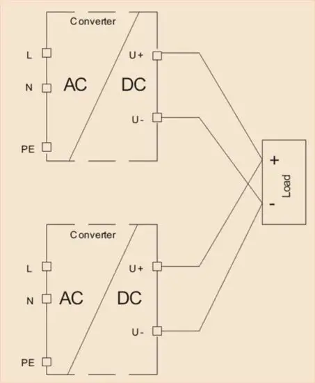
Parallel Operation & Decoupling
To increase the output power N+1 of the HPV units, two or more devices of the same model with the same output voltage can be parallel connected. Advise using busbars to connect several devices in parallel. Always use identical cabling length and identical cross-sections to the busbar or a star point. Allow proper connection for low contact resistance. The output voltage of each involved power supply unit must be adjusted 100% equal. Set the indicated switcher at the bottom of the power supply from “single” (factory preset) to “parallel” operation. The C/V characteristic line will slightly ream. The power-output distribution between the involved units will be more accurate.
The HPV models have no internal O-ring diode. For decoupling the devices N+1, up to 125Vdc, we recommend using our RED00202 DIN rail diode module. It is capable to decouple 2pcs of the HPV power supplies from each other. To increase the power capability RED models can be connected in parallel. For higher voltages, an external decoupling diode shall be installed by the system engineer.
Coating Option
We offer the HPV series with an optional coating. It is to be used in e.g., dusty, dirty, high humidity areas or in awaiting quick temperature changes. Short circuits and corrosion at print board lines and at solder points can be prevented. The coat itself is a transparent acrylic resin.
Peters SL 1306 N-FLZ (transparent) IEC60216-1 2001, IPC-CC-830B, UL listed as permanent coating File No.: E80315 , UL94V-0
Electrical Safety (Factory-Test / Field-Test Owner)
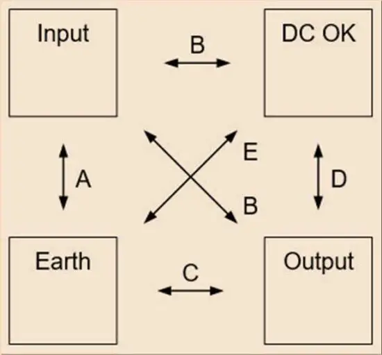
| T | A | B | C | D | E | |
| Type Test | 60s | 2500Vac | 3000Vac | 2500Vdc | 3000Vac | 500Vdc |
| Factory Test | 5s | 2000Vac | 2000Vac | 2500Vdc | 2000Vac | 500Vdc |
| Field Test | 2s | 2000Vac | 2000Vac | 2500Vdc | 2000Vac | 500Vdc |
| Cut-off current setting | >20mA | >20mA | >1mA | >1mA | >1mA | |
Type and factory test are the manufacturer. While repeating damage can happen to the power supply unit. For the field test (owner) follow the below instruction:
a) Use suitable test equipment, raising the voltage slowly
b) Short circuit L1 and N, and all the DC output terminals.
c) Use only test voltages of 50/60Hz. The outputs are unearthed and therefore they have no resistance to GND/PE.
d) If the residual voltage is ≥60Vdc, observe the safety standards.
Use only a specially insulated screwdriver to trim the Ua/Ia.
Mechanics
Mechanics
Stable metal/aluminum housing IP20. To allow adequate convection, a free air space of 50mm (top/bottom) and 10mm (sidewalls) is required; for active devices 15mm space from the sidewalls. For free air convection, it is necessary to install the unit horizontally. Use the DIN-Rail installation (equipped standard) with the patented 35mm DIN-Rail brackets according to EN60715. It is easy to mount/dismount while snaping it onto the 35mm DIN-Rail – no tools are necessary. A hard mount backplate (option) is available as well.
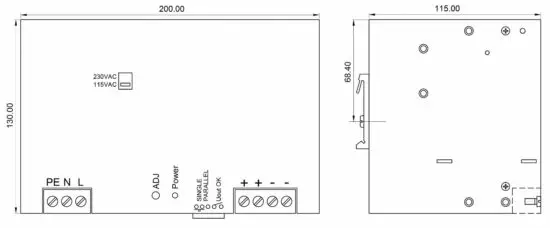
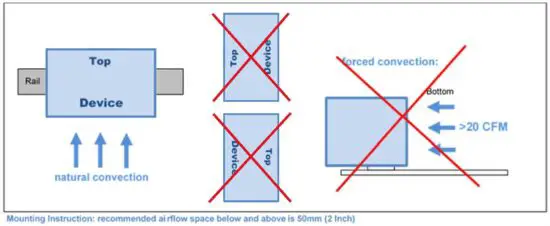
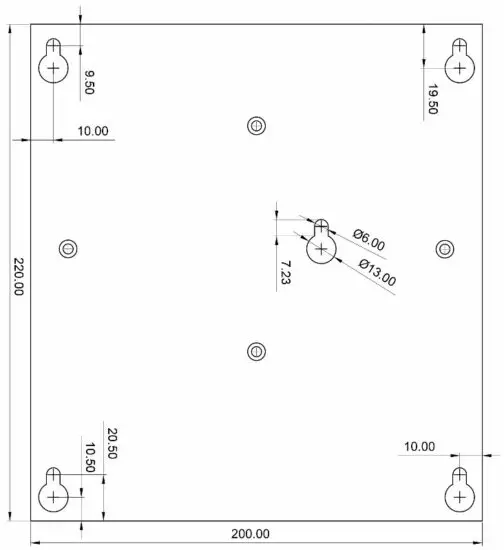
Mechanics & Installation Instruction of the HPV04801
Stable metal/aluminum housing IP20. To allow adequate convection, a free air space of 50mm (top/bottom) and 10mm (sidewalls) is required; and for active devices 15mm space from the sidewalls. For proper air convection, it is necessary to install the HPV04801. One can use the DIN-Rail installation (equipped standard) with our patented 35mm IN-Rail bracket according to EN60715. It is easy to mount/dismount while snaping it onto the 35mm DIN-Rail – no tools necessary. A wall mount backplate (option) is available, too.
It is not allowed to install the HPV04801 in other mounting directions than as shown in the drawings.
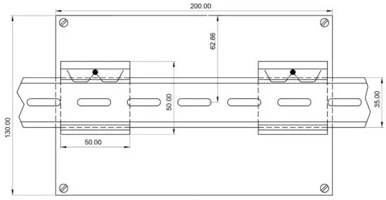
Back Plate Option / DIN-Rail Standard
(The HPV04801 is always delivered for DIN-rail mount, the back-plate is an optional part that shall be mounted by the customer. The threads from the DIN-rail mounting brackets shall be used. All screws are included in the Back-Plate Kit.)
Connections
Clamping Yoke Connector Specifications
| Input / Output connections | Power OK connection plug | |
| Tightening torque min. – max. | 1,2 – 2,2Nm (blade 1,0×5,5 DIN5264 ) | 0,2 – 0,25Nm (blade 0,4×2,2 DIN5264) |
| Touch-safe protection acc. to DIN VDE 0470 | IP20 plugged/ IP10 unplugged | Not applicable |
| Clamping range, min. – max. | 0,5 – 16mm² / AWG26 – AWG6 | 0,2 – 1,5mm² / AWG28 – AWG14 |
| Solid, H05(07) V-U min. – max. | 0,5 – 16mm² | 0,2 – 1,5mm² |
| Stranded, H05(07) V-U min. – max. | 6 – 16mm² | 0,2 – 1,5mm² |
| Flexible, H05(07) V-U min. – max. | 0,5 – 16mm² | 0,2 – 1,5mm² |
| w. plastic collar ferrule, DIN 46228 pt 4 min. – max. | 2,5 – 10mm² | 0,2 – 1,5mm² |
| w. wire end ferrule, DIN 46228 pt 1, min. – max. | 2,5 – 10mm² | 0,2 – 1,5mm² |
| Plug gauge in accordance with EN 60999 a x b; ø | 5,4 x 5,1mm; 5,3mm | 2,4 x 1,5mm; 2,3mm |
| Pitch (P) | 10,16mm | 3,5mm |
Wire Stripping Length (fine wired)
| Nominal Cross Section | Wire End Ferrule | Stripping Length | Wire End Ferrule | Stripping Length |
| 0,25mm² | H0,25/5 | 5mm | H0,25/10 HBL | 8mm |
| 0,5mm² | H0,5/6 | 6mm | H0,5/12 OR | 8mm |
| 1,0mm² | H1,0/6 | 6mm | H1,0/12 GE | 8mm |
| 2,5mm² | H2,5/12 | 12mm | H2,5/19D BL | 14mm |
| 4,0mm² | H4,0/12 | 12mm | H4,0/20 GDR | 14mm |
| 6,0mm² | H6,0/20 | 12mm | H6,0/20 SW | 14mm |
| 10,0mm² | H10,0/12 | 12mm | H10,0/22 EB | 15mm |
The length of ferrules is to be chosen depending on the rated voltage. The outside diameter of the plastic collar should not be larger than the pitch (P)
Ordering Information
Ordering Codes
| Product Code | Information | Power ok Relay | Article Number |
| HPV04801.072(R2) | 72V | No | 3041068001CA |
| HPV04801.110(R2) | 110V | No | 3041068002CA |
| HPV04801.150(R2) | 150V | No | 3041068003CA |
| HPV04801.220(R2) | 220V | No | 3041068004CA |
| HPV04801.072PG(R2) | 72V | Yes | 3041068011CA |
| HPV04801.110PG(R2) | 110V | Yes | 3041068012CA |
| HPV04801.150PG(R2) | 150V | Yes | 3041068013CA |
| HPV04801.220PG(R2) | 220V | Yes | 3041068014CA |
| Back Plate Kit | Base Plate / Hart mount plate kit including screws | – | 2201002001CA |
Safety regulations: Please read these instructions completely before using the equipment. Keep these instructions on hand. The device may only be operated by trained specialist staff.
Installation:
- The device is designed for devices and systems that meet the standard requirements for hazardous voltages, power, and fire prevention.
- Installation and service only by trained specialists.The AC power must be switched off. The work is to belabelled; accidental reconnection of the system must be prevented.
- Opening the device, its modification, loosening bolts, or operation outside the specified herein specification or in an unsuitable environment, has the immediate loss of warranty to follow. We disclaim any responsibility for any resulting damage to persons or things.
- Note: The device must not be operated without an upstream circuit breaker (CB). We recommend the use of C-Type 16A for 230Vac and for 115Vac. It is prohibited to use the unit without PE. It may be a necessary upstream device to have a power switch.
Warning:
Non-compliance with these warnings can result in fire and serious injury or death.
- Never operate a device without a PE connection.
- Before connecting the device to the AC network, make wires free of voltage and ensure that they cannot accidentally switch on.
- Allow neat and professional cabling.
- Never open nor try to repair the unit. Inside are dangerous voltages that can cause an electrical shock hazard.
- Avoid metal pieces or other conductive material to fall into the item
- Do not operate the device in damp or wet conditions
- Do not operate the unit under EX-conditions
![]()
![]()
All parameters base on 15 minutes run-in @ full load / 25°C / 230Vac 50/60Hz, as otherwise stated.
Camtec Power Supplies GmbH – Gewerbestrasse 30 – 76327 Pfinztal – Germany p.1/9 (06.2016.01.3)
Phone +49(721)46596-0 – Fax +49(721)46596-77 – www.camtec-gmbh.com – [email protected]
(Subject to alterations. This product is not designed to be used in applications such as life support systems wherein a failure or malfunction could result in injury or death)


