Regulus CSE TV ZV G 1F Pump Station
Product Information
- Product Name: CSE TV ZV G 1F Pump Station
- Manufacturer: REGULUS spol. s r.o.
- Website: www.regulus.eu
- Installation and Operation Manual: EN Manual
Introduction
This pump station is intended to ensure circulation in DHW distribution piping in buildings or to ensure hot water recirculation in DHW heating systems.
Description of the pump station
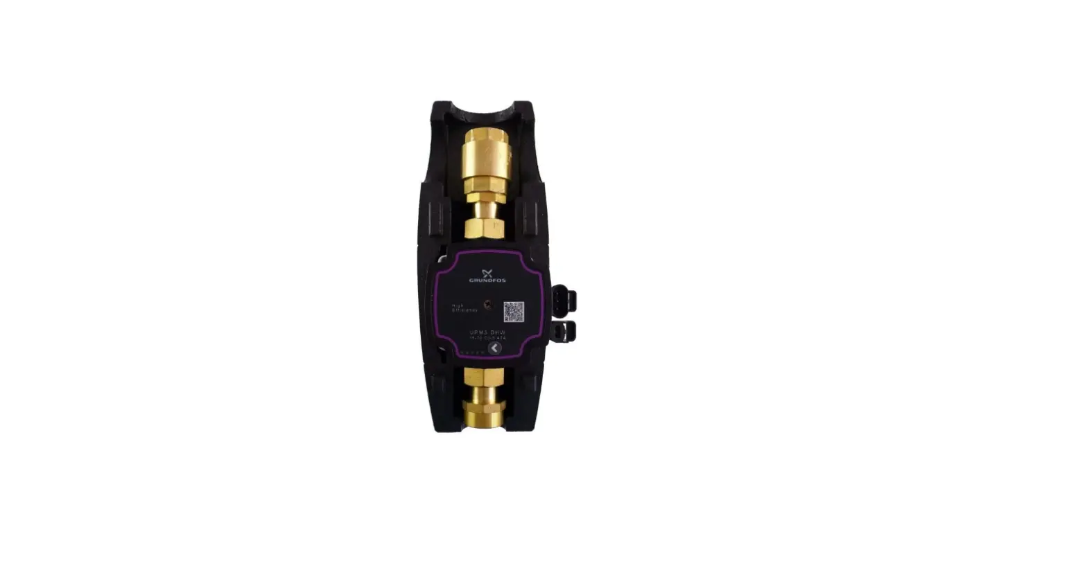
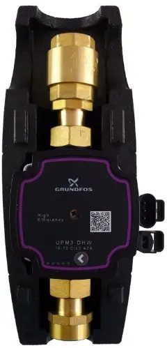
It consists of a UPM3 DHW 15-70 pump incl. power cable, insulation, check valve, two ball valves and thermometer.
| Main features | |
| Application | DHW circuits – recirculation or heating in a heat exchanger |
| Description | consists of UPM3 DHW 15-70 pump, insulation, valve, two ball valves and thermometer |
| Working fluid | water, drinking water |
| Installation | to the piping, min. distance of the pipe axis from a wall is 100 mm |
| Code | 15181 |
| Data of CSE TV ZV G 1F Pump Station | |
| Fluid working temperature | 2 – 95 °C |
| Max. working pressure | 10 bar |
| Min. working pressure | 0.5 bar |
| Ambient temperature | 5 – 40 °C |
| Max. rel. humidity | 80 %, non condensing |
| Power supply | 230 V, 50 Hz |
| Insulation material | EPP RG 60 g/l |
| Overall dimensions | 325 x 140 x 150 mm |
| Total weight | 2.0 kg |
| Connections | 2x G 1″ F |
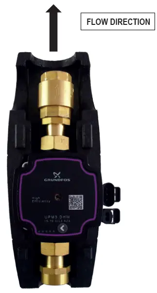
Direction of Flow through the Pump Station
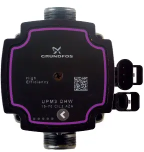
UPM3 DHW 15-70 Pump, 130 mm
Design
A wet-running circulation pump, G 1“ M connection.
| Electrical data | |
| Power supply | 230 V, 50 Hz |
| Power input (min./max.) | 2/52 W |
| Current (min./max.) | 0.04/0.52 A |
| IP rating | IP44 |
| Max. speed | 5766 rpm |
| Weighted average power | ≤ 23 W |
| Energy Efficiency Index | ≤ 0.20 by EN 16 297/3 |
| Motor protection | not needed |
Pump control
The circulation pump can be controlled without a PWM signal by selecting the pump performance curve or using an external PWM control signal (profile for use in heating systems). A PWM pump control cable with connector is not included. It can be purchased as an optional accessory (code 16792), cable length 2 m.
The maximum operating curve of the pump can be defined.
- with no PWM signal the pump runs at max. speed following the selected curve
- with PWM signal the pump speed changes with the signal value up to the maximum of the selected curve
Performance curves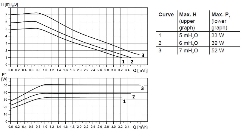
Performance display
The LED numbering is further omitted for better clarity.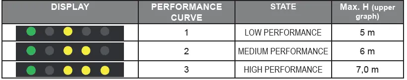
WARNING: LEDs may be mirrored, depending on the specific pump type.
| GREEN LED FLASHING FREQUENCY | GREEN LED FLASHING FREQUENCY |
| 1 flash per second | NO |
| 12 flashes per second | YES |
When switched on, the pump runs at factory settings or the last setting. The display shows the current pump performance.
Setting Selection for UPM3
To select your desired setting, press the button repeatedly until you find the setting you need (see the figure above). If you pass the desired setting, you have to go one more round until it appears again.
Error Display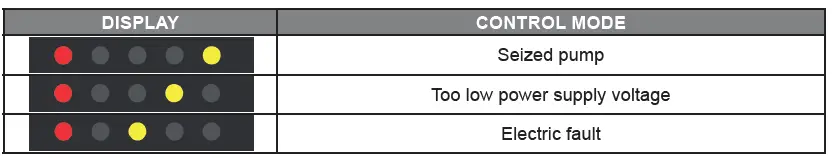
Prohibited positions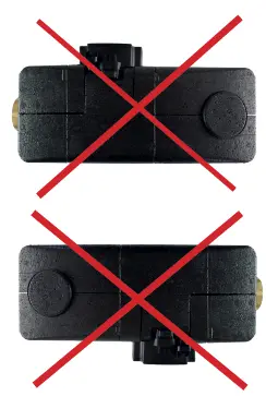
Permissible positions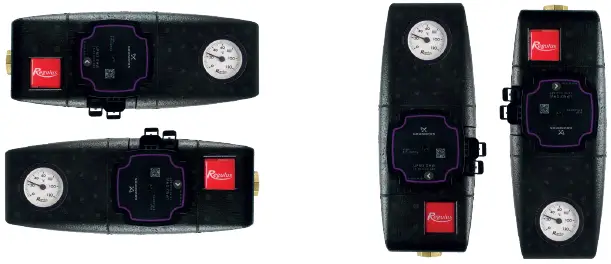
Pump Wiring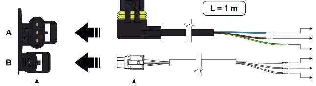
- socket for power supply (A)
- and signal transmission (B)
- power supply (A)
- and signal (B) connectors
- N (blue)
- L (brown)
- PE (yellow-green)
- PWM GDN (blue)
- iPWM out (black)
- PWM in (brown)
- connector (B) with 2m cable is not
- included in supply; it can be purchased as
- optional accessory, code 16792
Service
REGULUS spol. s r.o.
E-mail: [email protected]
Web: www.regulus.eu


