![]() 830 SERIES
830 SERIES
Troffer Installation Guide
830 Series Troffer
WARNING
- To avoid electric shock, disconnect power at source prior to installation.
- The installation should be performed by qualified electricians or lighting technicians.
- Before conducting any installation, maintenance, or removal, disable all power.
- Do not touch the fixture while it is in service.
- If there is any problem with the fixture, turn off power and DO NOT attempt repair unless you are a qualified technician or the customer service member.
Recessed Installation
| 1 | 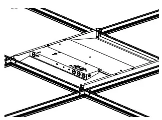 | Insert fixture into ceiling grid. |
| 2 | 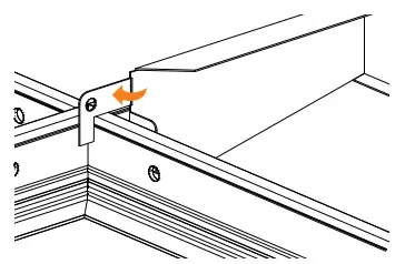 | Bend out mounting tabs 90degrees on each corner. |
| 3 | 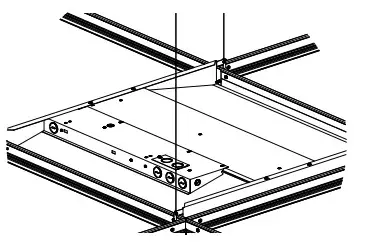 | Use hanger wire to tie off appropriately in accordance with local building codes. |
| 4 | 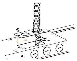 | Install conduit containing the conductors to the knockout of the cover plate and make all electrical connections to the fixture. Attach cover plate. |
Surface Mount Installation
| 1 | 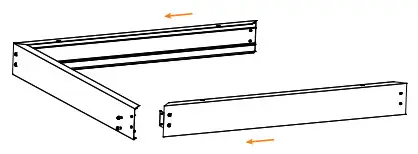 | Assemble three sides of the bracket with the included screws. |
| 2 | 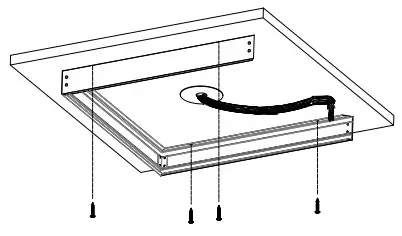 | With the open side facing the junction box, ensure the frame is square, then secure with appropriate fasteners. |
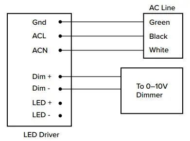
| 3 | 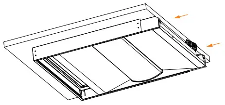 | Pull the conduit hose towards the open side, then insert luminaire partially into the mounting bracket. Make all electrical connections as shown in Wiring Diagram 2. |
| 4 | 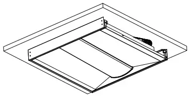 | Push the conduit hose back into the surface mount frame and fully insert the luminaire. When installed properly the luminaire will rest on the flanges of the frame. |
| 5 | 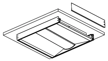 | Slide the final side of the frame into the slots, ensuring that it locks into place. Secure with the included screws. |
| 6 | 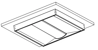 | Installation is complete. Your fixture is ready to power on. |
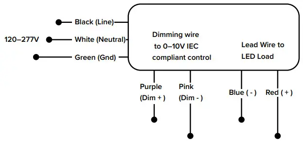
Wiring Diagram 1
Wiring Diagram 2
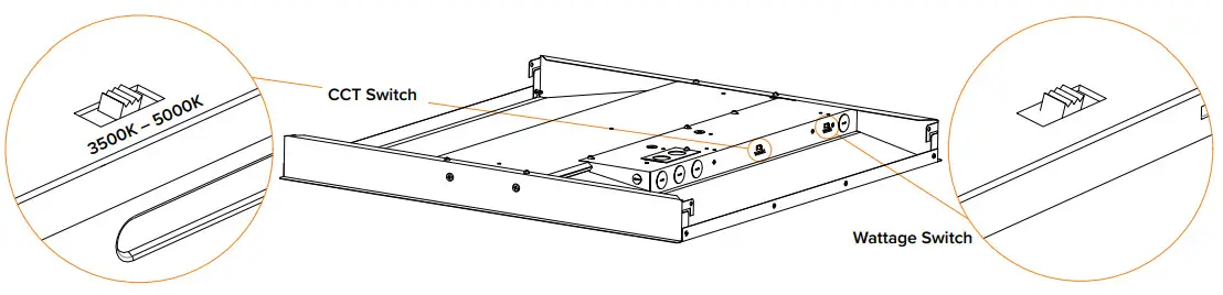
Field Adjustable Wattage and CCT
- Kelvin and wattage can be adjusted using the dip switches located on the driver.
- Select the desired kelvin and wattage by sliding the appropriate dip switch.

Copyright © 2022 ESL Vision, LLC. All rights reserved. Rev: 07/19/22![]() 888.493.5559
888.493.5559![]() [email protected]
[email protected]![]() www.eslvision.com
www.eslvision.com


