
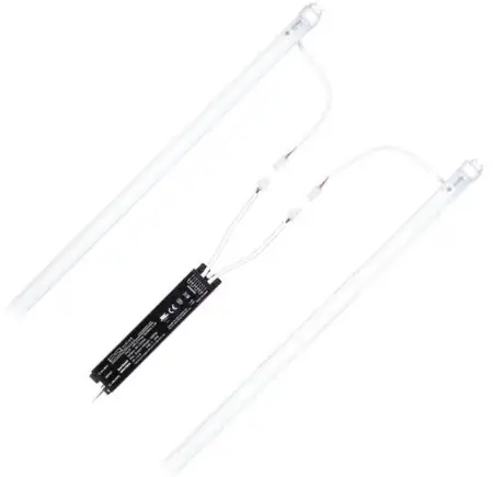
ESL VISION T8AB LED Retrofit Tube
WARNING
RISK OF FIRE OR ELECTRIC SHOCK. LED retrofit kit installation requires knowledge of luminaire electrical systems. Installation should only be performed by a qualified electrician in accordance with the applicable and appropriate electrical codes. If the lamp exhibits undesirable operation (buzzing, flickering, etc) immediately turn off power, remove lamp from fixture and contact ESL Vision.
ONE-ENDED WIRING WARNING: To avoid potential fire or shock hazard, do not use this retrofit kit in fixtures employing shunted bi-pin lampholders. (Note: Shunted lamp holders are found only in fluorescent fixtures with Instant-Start ballasts. Instant-start ballasts can be identified by the words “Instant Start” or “I.S.” marked on the ballast. This designation may be in the form of a statement pertaining to the ballast itself, or may be combined with the marking for the lamps with which the ballast is intended to be used, for example, F40T12/IS.)
- . Turn off electrical power before starting the installation of lamps.
- Before conducting any installation, maintenance, or removal, disable all power.
- Do not touch the lamp while it is in service.
- Intended for indoor use only. Maximum ambient temperature not to exceed 113°F (45°C)
- Avoid use in sunlight, abnormal heat or moist/condensing environments:
- Working temperature: -4°–113°F (029°C–45°C)
- Working humidity: 30%–80%
- Storage temperature: -40°F–149°F (-40°C–65°C)
- Storage humidity: 10%–90%
- Do not connect this lamp to a dimmer.
Installation Instructions
Direct Replacement (with existing ballast)
Check ballast compatibility before installation
- Turn Power Off
- Remove existing fluorescent lamp(s) from the fixture
- Install the LED replacement for each fluorescent removed
Bypass Replacement (with ballast removed)
- Disconnect the power from the fixture
- Remove existing fluorescent lamp(s) from the fixture
- Remove lens and wiring compartment, if applicable.
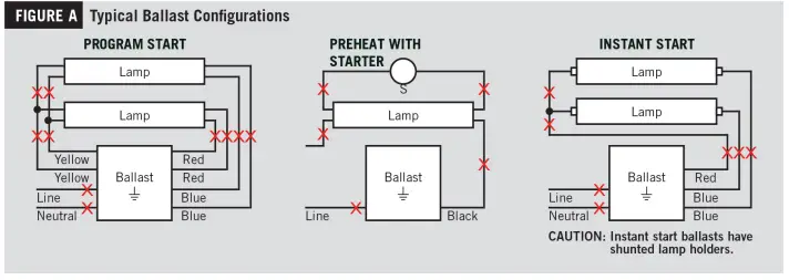
- Cut all wires connected to ballast (Figure A)
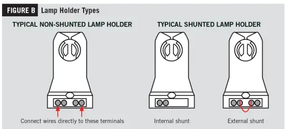
- Identify the type of lamp holders in the fixture; nonshunted or shunted (Figure B) and follow the instructions for Single or Double ended wiring.
Double Ended Line Voltage Wiring
Single Lamp
- Follow the steps for “Bypass Replacement (with ballast removed)”
- Cut all existing connections to ballast and remove ballast (Figure A)
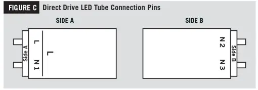
- Connect line voltage AC to both pins on Side A of the lamp (marked L and N1) on the endcap as shown below; on Side B, connect line neutral AC wire to pins marked N2 and N3 on the endcap as shown below (Figure C)

- Complete all electrical connections with appropriate connectors/wire nuts as needed, per all local and national electrical codes.
Note: there should not be any exposed wires from sockets left unconnected. - Replace wiring compartment cover.
- Ensure that installed lamp is wired to line and neutral in the lamp holder and that lamp is facing proper direction for illumination
- Install lens or diffuser, if applicable.
- Apply power to fixture and check for illumination
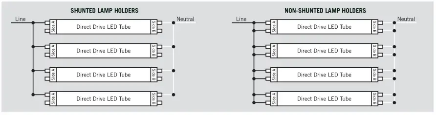
Double Lamp
- Follow the steps for “Bypass Replacement (with ballast removed)”
- Cut all existing connections to ballast and remove ballast (Figure A)
- Connect the terminals of the first lamp to the matching terminals of the second lamp with line and neutral wires. Continue daisychain connection for each additional lamp as shown below.

- Complete all electrical connections with appropriate connectors/wire nuts as needed, per all local and national electrical codes.
Note: there should not be any exposed wires from sockets left unconnected. - Replace wiring compartment cover.
- Ensure that installed lamp is wired to line and neutral in the lamp holder and that lamp is facing proper direction for illumination.
- Install lens or diffuser, if applicable.
- Apply power to fixture and check for illumination.
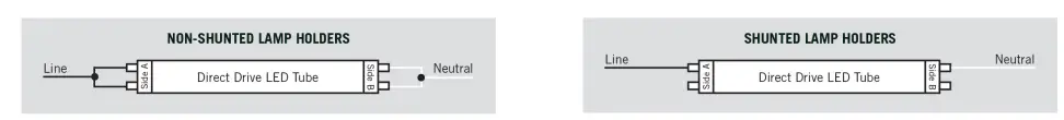
Single Ended Line Voltage Wiring
Single Lamp
- Follow the steps for “Bypass Replacement (with ballast removed)”
- Cut all existing connections to ballast and remove ballast (Figure A)
Note: Single-ended wiring requires non-shunted lamp holders (Figure B) - On Side A of lamp holder, connect line voltage AC wire to pin marked L and connect line neutral AC wire to pin marked N1 on theendcap as shown below (see Figure C, on page 3, for direct drive LED tube connection pins). Do not connect AC wires to Side B.

- Complete all electrical connections with appropriate connectors/wire nuts as needed, per all local and national electrical codes.
Note: there should not be any exposed wires from sockets left unconnected. - Replace wiring compartment cover.
- Ensure that installed lamp is wired to line and neutral in the lamp holder and that lamp is facing proper direction for illumination
- Install lens or diffuser, if applicable.
- Apply power to fixture and check for illumination

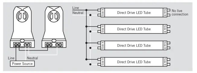
Double Lamp
- Follow the steps for “Bypass Replacement (with ballast removed)”
- Cut all existing connections to ballast and remove ballast (Figure A)
Note: Single-ended wiring requires non-shunted lamp holders (Figure B) - Connect the terminals of the first lamp to the matching terminals of the second lamp with line and neutral wires. Continue the daisy-chain connection for each additional lamp as shown below. Note: Do not connect any wires to Side B of the lamp holder.

- Complete all electrical connections with appropriate connectors/wire nuts as needed, per all local and national electrical codes.
Note: there should not be any exposed wires from sockets left unconnected. - Replace wiring compartment cover.
- Ensure that installed lamp is wired to line and neutral in the lamp holder and that lamp is facing proper direction for illumination.
- Install lens or diffuser, if applicable.
- Apply power to fixture and check for illumination.
Standard Voltage Compatibility
| START METHOD | # OF LAMPS | 1 LAMP LOAD | 2 LAMP LOAD | 3 LAMP LOAD | 4 LAMP LOAD | ||||||
| BRAND | PART NUMBER | INPUT VOLTAGE | INPUT VOLTAGE | INPUT VOLTAGE | INPUT VOLTAGE | ||||||
| 120V | 277V | 120V | 277V | 120V | 277V | 120V | 277V | ||||
| Arcata | ACT2P32ISUNV | IS | 2 | ✓ | ✓ | ✓ | ✓ | – | – | – | – |
| ACT4P32ISUNV | IS | 4 | – | – | – | – | ✓ | ✓ | ✓ | ✓ | |
| ICN-1P32-N | IS | 1 | ✓ | ✓ | – | – | – | – | – | – | |
| ICN-2P32-N | IS | 2 | x | x | ✓ | ✓ | – | – | – | – | |
| ICN-3P32-N | IS | 3 | – | – | ✓ | ✓ | ✓ | ✓ | – | – | |
| ICN-4P32-N | IS | 4 | – | – | ✓ | ✓ | ✓ | ✓ | – | – | |
| ICN-2P32-SC | IS | 2 | ✓ | ✓ | ✓ | ✓ | – | – | – | – | |
| ICN-4P32-SC | IS | 4 | – | – | – | – | x | ✓ | x | ✓ | |
| IOP-2P32-HL-N | IS | 2 | x | x | x | x | – | – | – | – | |
| IOP-4P32-HL-SC | IS | 4 | – | – | – | – | x | x | x | x | |
| Advance | IOPA-1P32-N | IS | 1 | ✓ | ✓ | – | – | – | – | – | – |
| IOPA-2P32-N | IS | 2 | x | x | ✓ | ✓ | – | – | – | – | |
| IOPA-3P32-N | IS | 3 | – | – | x | x | ✓ | ✓ | – | – | |
| IOPA-4P32-N | IS | 4 | – | – | – | – | ✓ | ✓ | ✓ | ✓ | |
| IOPA-1P32-LW-N | IS | 1 | x | x | – | – | – | – | – | – | |
| IOPA-2P32-LW-N | IS | 2 | x | x | ✓ | ✓ | – | – | – | – | |
| IOPA-4P32-LW-N | IS | 4 | – | – | – | – | ✓ | ✓ | ✓ | ✓ | |
| REL-2P32-SC | IS | 2 | ✓ | – | ✓ | – | – | – | – | – | |
| REZ-2S32-SC | IS | 2 | – | – | ✓ | – | – | – | – | – | |
| VE232MVHIPHE | IS | 2 | x | x | x | x | – | – | – | – | |
| ESPEN | VE232MVHIPLE | IS | 2 | ✓ | ✓ | ✓ | ✓ | – | – | – | – |
| VE432MVHIP | IS | 4 | – | – | – | – | ✓ | ✓ | ✓ | ✓ | |
| VE432MVHIPE | IS | 4 | – | – | – | – | ✓ | ✓ | ✓ | ✓ | |
| NPY-120-232-LT8 | PS | 2 | x | – | x | – | – | – | – | – | |
| NPY-120-432-T8B | IS | 4 | – | – | – | – | ✓ | – | ✓ | – | |
| Fulham | NPY-120-432-T8-IS | IS | 4 | – | – | – | – | ✓ | – | ✓ | – |
| WHCG3-120-T8-IS | IS | 3 | – | – | ✓ | – | ✓ | – | – | – | |
| WH2-120-L | IS | 1 | ✓ | – | – | – | – | – | – | – | |
| WH5-120-L | IS | 4 | – | – | – | – | x | – | x | – | |
| FB232MVE | IS | 2 | ✓ | ✓ | ✓ | ✓ | – | – | – | – | |
| FB232MVE-N | IS | 2 | ✓ | ✓ | ✓ | ✓ | – | – | – | – | |
| FB232MVE-HE | IS | 2 | ✓ | ✓ | ✓ | ✓ | – | – | – | – | |
| FB232MVE-LHE | IS | 2 | ✓ | – | ✓ | – | – | – | – | – | |
| Fusion | FB232MVE-PPS-HE | PS | 2 | ✓ | ✓ | ✓ | ✓ | – | – | – | – |
| FB332MVE | IS | 3 | – | – | ✓ | ✓ | ✓ | ✓ | – | – | |
| FB432MVE | IS | 4 | – | – | – | – | ✓ | ✓ | ✓ | ✓ | |
| FB432MVE-HE | IS | 4 | – | – | – | – | ✓ | ✓ | ✓ | ✓ | |
| FB432MVE-N | IS | 4 | – | – | – | – | ✓ | ✓ | ✓ | ✓ | |
| FB432MVE-PPS-HE | PS | 4 | – | – | – | – | ✓ | ✓ | ✓ | ✓ | |
| GE132MAX-L/ULTRA | IS | 1 | ✓ | ✓ | – | – | – | – | – | – | |
| GE132MAXP-L/ULTRA | IS | 1 | ✓ | ✓ | – | – | – | – | – | – | |
| GE132MAX-N/ULTRA | IS | 1 | ✓ | ✓ | – | – | – | – | – | – | |
| GE132MAXP-N/ULTRA | IS | 1 | ✓ | ✓ | – | – | – | – | – | – | |
| GE132MAXP-H/ULTRA | IS | 1 | x | x | – | – | – | – | – | – | |
| GE132MAX-G-N | IS | 1 | ✓ | ✓ | – | – | – | – | – | – | |
| GE232MAX-L/ULTRA | IS | 2 | ✓ | ✓ | ✓ | ✓ | – | – | – | – | |
| GE232MAXP-L/ULTRA | IS | 2 | ✓ | ✓ | ✓ | ✓ | – | – | – | – | |
| GE232MAX-N/ULTRA | IS | 2 | ✓ | ✓ | ✓ | ✓ | – | – | – | – | |
| GE232MAXP-N/ULTRA | IS | 2 | ✓ | ✓ | ✓ | ✓ | – | – | – | – | |
| GE232MAXP-H/ULTRA | IS | 2 | x | x | x | x | – | – | – | – | |
| GE232MAX-G-L | IS | 2 | ✓ | ✓ | ✓ | ✓ | – | – | – | – | |
| GE232MAX-G-N | IS | 2 | ✓ | ✓ | ✓ | ✓ | – | – | – | – | |
| GE | GE232MAX-G-H | IS | 2 | x | x | x | x | – | – | – | – |
| GE232MV-H | IS | 2 | x | x | x | x | – | – | – | – | |
| GE 232-120-PS-N | PS | 2 | ✓ | – | ✓ | – | – | – | – | – | |
| GE232-MVPS-L | PS | 2 | ✓ | x | ✓ | x | – | – | – | – | |
| GE232-MVPS-H | PS | 2 | x | x | x | x | – | – | – | – | |
| LEDET8/DR/2L/H | IS | 2 | x | x | ✓ | ✓ | – | – | – | – | |
| LEDET8/DR/2L/H-G2 | IS | 2 | ✓ | x | ✓ | ✓ | – | – | – | – | |
| GE232MVPS-N-V03 | PS | 2 | ✓ | ✓ | ✓ | ✓ | – | – | – | – | |
| GE332MAX-L/ULTRA | IS | 3 | – | – | ✓ | ✓ | ✓ | ✓ | – | – | |
| GE332MAXP-L/ULTRA | IS | 3 | – | – | ✓ | ✓ | ✓ | ✓ | – | – | |
| GE332MAXP-N/ULTRA | IS | 3 | – | – | ✓ | ✓ | ✓ | ✓ | – | – | |
| GE332MAX-H/ULTRA | IS | 3 | – | – | x | x | x | x | – | – | |
| GE332MAXP-H/ULTRA | IS | 3 | – | – | x | x | x | x | – | – | |
| GE332MAX-G-L | IS | 3 | – | – | ✓ | ✓ | ✓ | ✓ | – | – | |
| START METHOD | # OF LAMPS | 1 LAMP LOAD | 2 LAMP LOAD | 3 LAMP LOAD | 4 LAMP LOAD | ||||||
| BRAND | PART NUMBER | INPUT VOLTAGE | INPUT VOLTAGE | INPUT VOLTAGE | INPUT VOLTAGE | ||||||
| 120V | 277V | 120V | 277V | 120V | 277V | 120V | 277V | ||||
| GE332MAX-G-N | IS | 3 | – | – | ✓ | ✓ | ✓ | ✓ | – | – | |
| GE332MAX-G-H | IS | 3 | – | – | x | x | x | x | – | – | |
| GE332MV-H | IS | 3 | – | – | x | x | x | x | – | – | |
| GE332MAX90-V60 | IS | 3 | – | – | x | x | x | x | – | – | |
| GE332MV-N-DIY | IS | 3 | – | – | ✓ | ✓ | ✓ | ✓ | – | – | |
| GE332MVPS-N-V03 | PS | 3 | – | – | ✓ | ✓ | ✓ | ✓ | – | – | |
| GE432MAX-L/ULTRA | IS | 4 | – | – | – | – | x | x | ✓ | ✓ | |
| GE432MAXP-L/ULTRA | IS | 4 | – | – | – | – | ✓ | ✓ | ✓ | ✓ | |
| GE432MAX-N/ULTRA | IS | 4 | – | – | – | – | ✓ | ✓ | ✓ | ✓ | |
| GE432MAXP-N/ULTRA | IS | 4 | – | – | – | – | ✓ | ✓ | ✓ | ✓ | |
| GE432MAX-H/ULTRA | IS | 4 | – | – | – | – | x | x | x | x | |
| GE | GE432MAXP-H/ULTRA | IS | 4 | – | – | – | – | x | x | x | x |
| GE432MAX-G-L | IS | 4 | – | – | – | – | ✓ | ✓ | ✓ | ✓ | |
| GE432MAX-G-N | IS | 4 | – | – | – | – | ✓ | ✓ | ✓ | ✓ | |
| GE432MAX-G-H | IS | 4 | – | – | – | – | x | x | x | x | |
| GE432MV-N | IS | 4 | – | – | – | – | ✓ | ✓ | ✓ | ✓ | |
| GE432MV-H | IS | 4 | – | – | – | – | x | x | x | x | |
| LEDET8/DR/4L/H | IS | 4 | – | – | – | – | ✓ | ✓ | ✓ | ✓ | |
| LEDET8/DR/4L/H-G2 | IS | 4 | – | – | – | – | ✓ | ✓ | ✓ | ✓ | |
| GE432-120-N | IS | 4 | – | – | – | – | ✓ | – | ✓ | – | |
| GE432MAX-H-42T | IS | 4 | – | – | – | – | x | x | x | x | |
| GE432MV-N-DIY | IS | 4 | – | – | – | – | ✓ | ✓ | ✓ | ✓ | |
| GE432MVPS-N-V03 | PS | 4 | – | – | – | – | ✓ | ✓ | ✓ | ✓ | |
| Greenhill | GH4P32ISUNV | IS | 4 | – | – | – | – | ✓ | ✓ | ✓ | ✓ |
| EP332IS/MV/MC | IS | 3 | – | – | ✓ | ✓ | ✓ | ✓ | – | – | |
| Halco | EP432IS/L/MV/HE | IS | 4 | – | – | – | – | ✓ | ✓ | ✓ | ✓ |
| EP432IS/MV/MC | IS | 4 | – | – | – | – | ✓ | ✓ | ✓ | ✓ | |
| Howard | EP4/32IS/MV/MC/HE | IS | 4 | – | – | – | – | ✓ | x | ✓ | ✓ |
| Huafeng | ENI-T8-32-P2SC-N | IS | 2 | ✓ | ✓ | ✓ | ✓ | – | – | – | – |
| ENI-T8-32-P4MC-N | IS | 4 | – | – | – | – | x | ✓ | x | ✓ | |
| KTEB-132-UV-IS-L-P | IS | 1 | ✓ | ✓ | – | – | – | – | – | – | |
| KTEB-132-UV-PS-N-P | IS | 1 | ✓ | ✓ | – | – | – | – | – | – | |
| KTEB-232-UV-IS-L-P | IS | 2 | ✓ | ✓ | ✓ | ✓ | – | – | – | – | |
| KTEB-232-UV-IS-N-P | IS | 2 | ✓ | ✓ | ✓ | ✓ | – | – | – | – | |
| KTEB-232-UV-IS-H-P | IS | 2 | x | x | x | x | – | – | – | – | |
| KTEB-232-UV-PS-VDIM | PS | 2 | – | – | x | ✓ | – | – | – | – | |
| KTEB-232-UV-PS-H-P | PS | 2 | x | x | x | x | – | – | – | – | |
| KTEB-332-UV-IS-L-P | IS | 3 | – | – | ✓ | ✓ | ✓ | ✓ | – | – | |
| Keystone | KTEB-332-UV-IS-N-P | IS | 3 | – | – | ✓ | ✓ | ✓ | ✓ | – | – |
| KTEB-332-UV-IS-H-P | IS | 3 | – | – | x | x | x | x | – | – | |
| KTEB-332-UV-PS-L-P | PS | 3 | – | – | ✓ | ✓ | ✓ | ✓ | – | – | |
| KTEB-332-UV-PS-N-P | PS | 3 | – | – | ✓ | ✓ | ✓ | ✓ | – | – | |
| KTEB-332-UV-PS-H-P | PS | 3 | – | – | x | x | x | x | – | – | |
| KTEB-432-UV-IS-L-P | IS | 4 | – | – | – | – | ✓ | ✓ | ✓ | ✓ | |
| KTEB-432-UV-IS-N-P | IS | 4 | – | – | – | – | ✓ | ✓ | ✓ | ✓ | |
| KTEB-432-UV-IS-H-P | IS | 4 | – | – | – | – | x | x | x | x | |
| KTEB-432-UV-PS-L-P | PS | 4 | – | – | – | – | ✓ | ✓ | ✓ | ✓ | |
| KTEB-432-UV-PS-N-P | PS | 4 | – | – | – | – | ✓ | ✓ | ✓ | ✓ | |
| QHE 1X32T8/UNV ISN-SC | IS | 1 | ✓ | ✓ | – | – | – | – | – | – | |
| QTP 1X32T8/UNV ISN-SC | IS | 1 | ✓ | ✓ | – | – | – | – | – | – | |
| QHE 2X32T8/UNV ISL-SC | IS | 2 | ✓ | ✓ | ✓ | ✓ | – | – | – | – | |
| Osram | QTP 2X32T8/UNV ISL-SC | IS | 2 | ✓ | ✓ | ✓ | ✓ | – | – | – | – |
| QHE 2X32T8/UNV ISN-SC | IS | 2 | ✓ | ✓ | ✓ | ✓ | – | – | – | – | |
| QTP 2X32T8/UNV ISN-SC | IS | 2 | ✓ | ✓ | ✓ | ✓ | – | – | – | – | |
| QTP 4x32T8/UNV ISN-SC | IS | 4 | – | – | – | – | ✓ | ✓ | ✓ | ✓ | |
| Pacific | EB-332IS-U | IS | 3 | – | – | ✓ | ✓ | ✓ | ✓ | – | – |
| EB-432IS-U | IS | 4 | – | – | – | – | ✓ | ✓ | ✓ | ✓ | |
| PQL | 70201 | IS | 2 | ✓ | ✓ | ✓ | ✓ | – | – | – | – |
| 70204 | IS | 4 | – | – | – | – | ✓ | ✓ | ✓ | ✓ | |
| Premium | BB-T8/UVH-2×32 | IS | 2 | ✓ | ✓ | ✓ | ✓ | – | – | – | – |
| BB-T8/UVH-3×32 | IS | 3 | – | – | – | – | ✓ | ✓ | – | – | |
| Robertson | RSW240T12120 | PS | 2 | ✓ | – | ✓ | – | – | – | – | – |
| E232PI120L | IS | 2 | ✓ | – | ✓ | – | – | – | – | – | |
| Standard | E432T8IS120/H | IS | 4 | – | – | – | – | x | – | x | – |
| E432T8IS120/N/AS/BULK | IS | 4 | – | – | – | – | ✓ | – | ✓ | – | |
| START METHOD | # OF LAMPS | 1 LAMP LOAD | 2 LAMP LOAD | 3 LAMP LOAD | 4 LAMP LOAD | ||||||
| BRAND | PART NUMBER | INPUT VOLTAGE | INPUT VOLTAGE | INPUT VOLTAGE | INPUT VOLTAGE | ||||||
| 120V | 277V | 120V | 277V | 120V | 277V | 120V | 277V | ||||
| Sunpark | SL15T | PS | 2 | x | – | ✓ | – | – | – | – | – |
| B232PUSV3PLA | PS | 2 | x | x | x | x | – | – | – | – | |
| B232SR120S30 | PS | 2 | – | – | x | – | – | – | – | – | |
| B232IUNVHE-A | IS | 2 | ✓ | ✓ | ✓ | ✓ | – | – | – | – | |
| Universal | B232IUNVEL-N | IS | 2 | – | – | – | – | ✓ | ✓ | ✓ | ✓ |
| B232IUNVHP-N | IS | 2 | – | – | – | – | ✓ | ✓ | ✓ | ✓ | |
| B432IUNVHE-A | IS | 2 | – | – | – | – | ✓ | ✓ | ✓ | ✓ | |
| B432IUNVEL-A | IS | 4 | – | – | – | – | ✓ | ✓ | ✓ | ✓ | |
| B432IUNVHP-A | IS | 4 | – | – | – | – | ✓ | ✓ | ✓ | ✓ | |
High Voltage Compatibility
| START METHOD | # OF LAMPS | 1 LAMP LOAD | 2 LAMP LOAD | 3 LAMP LOAD | 4 LAMP LOAD | ||||||
| BRAND | PART NUMBER | INPUT VOLTAGE | INPUT VOLTAGE | INPUT VOLTAGE | INPUT VOLTAGE | ||||||
| 347V | 480V | 347V | 480V | 347V | 480V | 347V | 480V | ||||
| Arcata | ACT2P32IS347 | IS | 2 | ✓ | ✓ | ✓ | ✓ | – | – | – | – |
| ACT4P32IS347 | IS | 4 | – | – | – | – | ✓ | ✓ | ✓ | ✓ | |
| Advance | GOPA-2P32-LW-SC | IS | 2 | ✓ | – | ✓ | – | – | – | – | – |
| GOPA-4P32-LW-SC | IS | 4 | – | – | – | – | ✓ | – | ✓ | – | |
| GOPA-2P32-SC | IS | 2 | ✓ | – | ✓ | – | – | – | – | – | |
| GOPA-4P32-SC | IS | 4 | – | – | – | – | ✓ | – | ✓ | – | |
| Fusion | FB232347E-HE | IS | 2 | ✓ | – | ✓ | – | – | – | – | – |
| FB232347E-L | IS | 2 | ✓ | – | ✓ | – | – | – | – | – | |
| FB232347E-N | IS | 2 | ✓ | – | ✓ | – | – | – | – | – | |
| FB232347E-PPS-HE | PS | 2 | ✓ | – | ✓ | – | – | – | – | – | |
| FB432347E-HE | IS | 4 | – | – | – | – | ✓ | – | ✓ | – | |
| FB432347E-L | IS | 4 | – | – | – | – | ✓ | – | ✓ | – | |
| FB432347E-N | IS | 4 | – | – | – | – | ✓ | – | ✓ | – | |
| FB432347E-PPS-HE | PS | 4 | – | – | – | – | ✓ | – | ✓ | – | |
| GE | GE232MAX347-H | IS | 2 | x | – | x | – | – | – | – | – |
| GE232PS347-N | PS | 2 | ✓ | – | ✓ | – | – | – | – | – | |
| GE332MAX347-H | IS | 3 | – | – | x | – | x | – | – | – | |
| GE432MAX347-H | IS | 4 | – | – | – | – | x | – | x | – | |
| GE432PS347-N | PS | 4 | – | – | – | – | ✓ | – | ✓ | – | |
| Keystone | KTEB-232-3-IS-N-P | IS | 2 | ✓ | – | ✓ | – | – | – | – | – |
| KTEB-432-3-IS-N-P | IS | 4 | – | – | – | – | ✓ | – | ✓ | – | |
| Osram | QHE 2×32 T8/347 ISL-SC | IS | 2 | ✓ | – | ✓ | – | – | – | – | – |
| QHE 2×32 T8/347 ISN-SC | IS | 2 | ✓ | – | ✓ | – | – | – | – | – | |
| Standard | E232T8IS347/H/90C | IS | 2 | x | – | x | – | – | – | – | – |
| E232T8IS347/L/BULK | IS | 2 | ✓ | – | ✓ | – | – | – | – | – | |
| E232T8IS347/N/BULK | IS | 2 | x | – | ✓ | – | – | – | – | – | |
| E432PI347G01 | IS | 4 | – | – | – | – | ✓ | – | ✓ | – | |
| E432T8IS347/L/BULK | IS | 4 | – | – | – | – | ✓ | – | ✓ | – | |
| E432T8IS347/N | IS | 4 | – | – | – | – | ✓ | – | ✓ | – | |
| E432T8IS347/N/BULK | IS | 4 | – | – | – | – | ✓ | – | ✓ | – | |
| E432T8IS347/H/90C | IS | 4 | – | – | – | – | x | – | x | – | |
| Universal | B232I347HE-A | IS | 2 | ✓ | – | ✓ | – | – | – | – | – |
| B432I347HE-A | IS | 4 | – | – | – | – | ✓ | – | ✓ | – | |
Emergency Ballast Compatibility
| BRAND | PART NUMBER | COMPATIBLE |
| Keystone | KT-EMRG-500 | ✓ |
| KT-EMRG-1300-T5 | ✓ | |
| KT-EMRG-1400-SL | x | |
| Philips | Dobine B50 | ✓ |
| Dobine ELI-S-20 | ✓ | |
| Dobine LP600 | ✓ | |
| LOTA | I-320 | ✓ |
| ISL-540 | ✓ |
888.493.5559
Copyright © 2022 ESL Vision, LLC. All rights reserved. Rev: 01/10/22


