![]() 650W/1200W Modular Power
650W/1200W Modular Power
NMP series
Owner’s Manual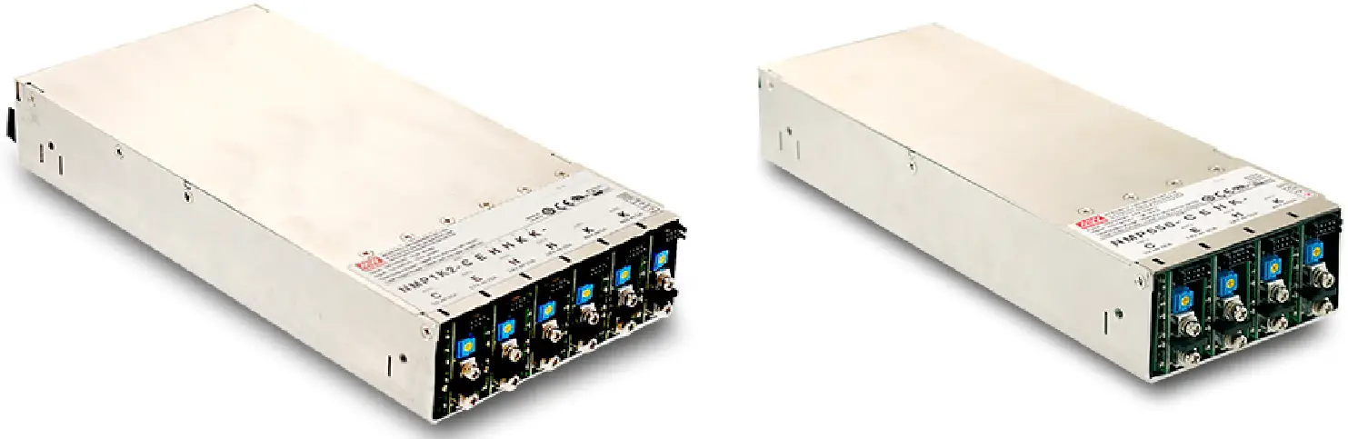
![]()
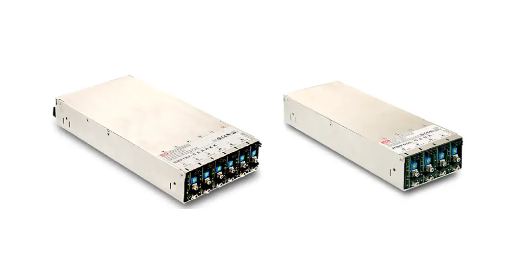
NMP Series 1200W Modular Power
 |  |
| https://www.meanwell.com/webapp/product/search.aspx?prod=NMP650&pdf=Tk1QLUUucGRm&a=4 | https://www.youtube.com/watch?v=X3gNhyXBAKQ&list=PLvUyt_OJELVrHoIIRgvHF2NQ-j39-NH-J&index=14 |
Features
- Medical (2x MOPP) ITE safety approvals
- Suitable for BF application with appropriate system consideration (Touch current < 100uA/264VAC)
- 1U low profile
- Universal AC input / Full range
- Output voltage and current programmable
- Built-in parallel function / output programmable / global enable / remote local ON-OFF / auxiliary DC output / over temperature alarm / DC OK
- Cooling by thermostatically controlled fan with fan alarm function
- Protections: Short circuit / Overload / Over voltage / Over temperature for all output modules
- 5 years warranty
Applications
- Medical equipment
- Diagnostic or biological facilities
- MRI, CT and PET scanners
- Test or measurement systems
- Telecommunication equipment
- Factory automation and aging equipment
- Laser equipment
GTIN CODE
MW Search: https://www.meanwell.com/serviceGTIN.aspx
Description
NMP family is a 1U low profile modular and configurable type power supply from MEAN WELL. This family comprises two power wattage for the line-up, 650W and 1200W, and the output modules deliver up to 240W with adjustable options for the major working voltages used in the industries 5V, 12V, 24V, 48V, Dual Output. NMP family complies with safety approval, the medical (2x MOPP between primary to secondary) and ITE standards. Offering the best flexibility for various types of applications.
Output Configuration Guide
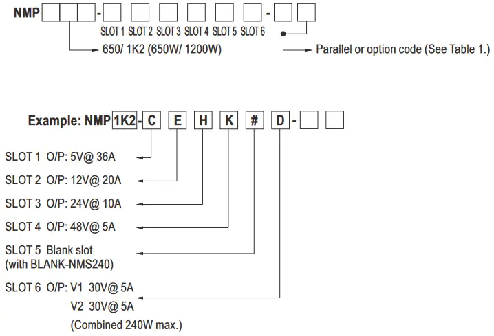 ※650W (4 SLOTS)、1200W (6 SLOTS)
Table 1. Parallel or option code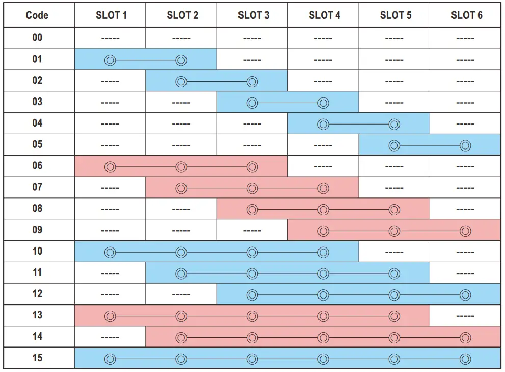
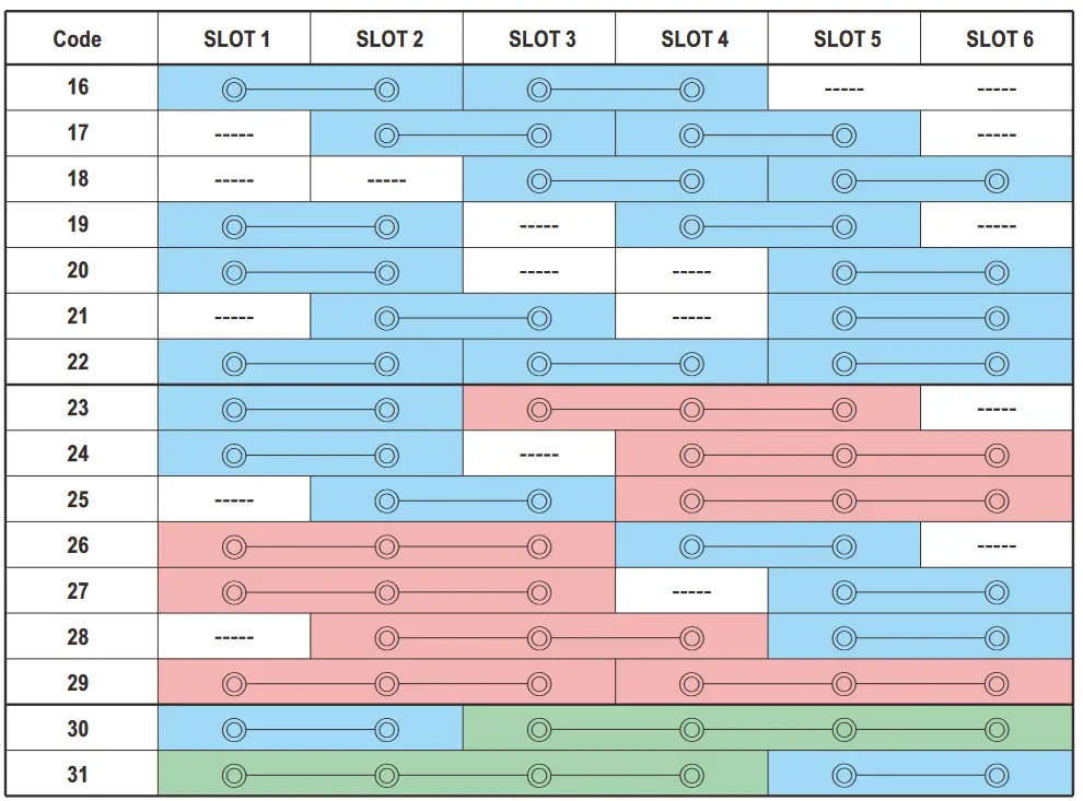 ※Code 00, 01, 02, 03, 06, 07, 10, 16 for NMP650
※Code 00~31 for NMP1K2
SPECIFICATION
Front-End
| MODEL | NMP650 (4 Slots) | I NMPI K2 (6 Slots) | |||
| INPUT | VOLTAGE RANGE Wel | 90 – 264VAC 120 -370VDC | |||
| FREQUENCY RANGE | 47 – 63Hz | ||||
| POWER FACTOR | PF>0.95/230VAC PF>0.98/115VAC at full load | ||||
| EFFICIENCY(Typ.) Note.4 | 91%, full case load with H / K module at nominal 24V / 48V only | 90.5%, full case load with H / K module at nominal 24V /48V only | |||
| 88.5%, full case load with each type of module at nominal voltage | |||||
| AC CURRENT | 3.5Al230VAC 7.5N115VAC | 6.7N230VAC 13.5N115VAC | |||
| INRUSH CURRENT | 40A/230VAC 25A/115VAC | 40A/230VAC 25A/115VAC | |||
| LEAKAGE CURRENT | Earth leakage current <400uA/ 264VAC, Touch current <100uN264VAC | ||||
| OUTPUT | TOTAL OUTPUT POWER | 650W max. | 1200W max. | ||
| PROTECTION | OVER TEMPERATURE | Shut down o/p voltage, recovers automatically after temperature goes down | |||
| FUNCTION | REMOTE CONTROL | RC+/RC-: Short, Power ON RC+IRC-: Open. Power OFF | |||
| ALARM SIGNAL | TTL signal output for over temperature alarm. Please refer to the Function Manual. | ||||
| AUXILIARY POWER(AUX) | 5V © 1.5A ; tolerance ±10%; ripple: 50mVp-p (max.) | 5V @ 2A; tolerance ±10%; ripple: 50mVp-p(max.) | |||
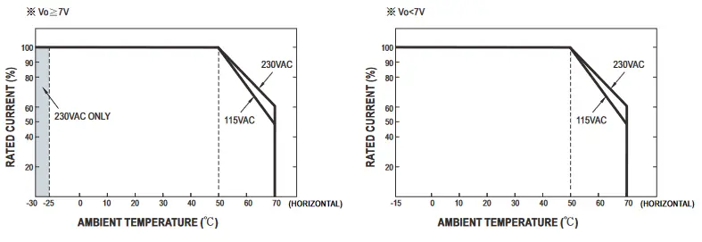
| ENVIRONNEW | WORKING TEMP. | -30 – +70°C (Derate at 50°C, refer to ‘Derating Curve”) | |||
| WORKING HUMIDITY | 20 – 90% RH non-condensing | ||||
| STORAGE TEMP., HUMIDITY | -40 – +85°C , 10 – 95% RH non-condensing | ||||
| TEMP. COEFFICIENT | ±0.03%/°C (0 – 50°C ) | ||||
| VIBRATION | 10-500Hz, 2G 10minJ1 cycle, 60 min. each along X, Y, Z axes. | ||||
| SAFETY 8, EMC (Note 5) | SAFETY STANDARDS | ANSI/AAMI ES60601-1, Ed. 3.1 ,UL62368-1; TUV BS ENIEN60601-1, Ed. 3.1, TUV BS EN/EN62368-1; IEC 60601-1. Ed. 3.1. IEC 62368-1. IEC60950-1; EAC TP TC 004 approved | |||
| ISOLATION LEVEL | Primary-Secondary: 2x MOPP, Primary-Earth: lx MOPP | ||||
| WITHSTAND VOLTAGE | UP-0/P: 4KVAC I/P-FG: 2KVAC 0/P-FG: 0.5KVAC | ||||
| ISOLATION RESISTANCE | UP-0/P, UP-FG. 0/P-FG: 100M Ohms! 500VDC / 25°C! 70% RH | ||||
| EMC EMISSION | Parameter | Standard | Test Level! Note | ||
| Conducted | BS EN/EN55032 (CISPR32)/ 8S ENIEN55011 (CISPRII) | Class B | |||
| Radiated | BS ENENS5032 (CISPR32)I BS ENEN55011 (CISPR11) | Class B | |||
| Harmonic Current | BS EN/EN61000-3-2 | Class A | |||
| Voltage Flicker | BS ENIEN61000-3-3 | ||||
| EMC IMMUNITY | BS EN/EN60601-1-2, BS EN/EN55035, SEMI F47 | ||||
| Parameter | Standard | Test Level I Note | |||
| ESD | BS ENIEN61000-4-2 | Level 4, 151Q/ air; Level 4, 8KV contact | |||
| RF field | BS ENIEN61000-4-3 | Level 3. 10V/m | |||
| EFT! Burst | BS EN/EN61000-4-4 | Level 3, 21W | |||
| Surge | BS ENIEN61000-4-5 | Level 4, 4KV/Line-FG; 2KV/Line-Line | |||
| Conducted | BS ENIEN61000-4-6 | Level 2, 3V | |||
| Magnetic Field | BS ENIEN61000-4-8 | Level 4, 30AIrn | |||
| Voltage Dips and Interruptions | BS EN/EN61000-4-11 | 100% dip 1 periods, 30% dip 25 periods, 100% interruptions 250 periods | |||
| OTHERS | MTBF | 1314.6K hrs min. Telcordia SR-332 (Bellcore) ;128.2K hrs min. MIL-HDBK-217F (25°C) (NMP650) 1275.4K hrs min. Telcordia SR-332 (Bellcore) ; 124.5K hrs min. MIL-HDBK-217F (25°C) (NMP1K2) | |||
| DIMENSION | 250*89*41mm (L*W*H) | 250’12711mm (L*W*H) | |||
| PACKING | 1.45Kg (typ.); 9pcs / 14Kg I 0.98CUFT | 2Kg (typ.); 6pcs/13Kg/0.88CUFT | |||
Single Output Module (240W)
| OUTPUT (NMS-240) | MODEL | NMS-240-05 | NMS-240-12 | NMS-240-24 | NMS-240-48 |
| CONFIGURATION CODE | C | E | H | K | |
| DC VOLTAGE | 5V | 12V | 24V | 48V | |
| RATED CURRENT | 36A | 20A | 10A | 5A | |
| CURRENT RANGE | 0 – 36A | 0 – 20A | 0 – 10A | 0 – 5A | |
| RATED POWER | 180W | 240W | 240W | 240W | |
| RIPPLE & NOISE (max.) Note.2 | 100mVp-p | 150mVp-p | 150mVp-p | 250mVp-p | |
| VOLTAGE ADJ. RANGE | 3 – 6V | 6-15V | 15-30V | 30-55V | |
| VOLTAGE TOLERANCE Noto.3 | ±2.0% | ±1.0% | ±1.0% | ±1.0% | |
| LINE REGULATION | ±0.5% | ±0.3% | ±0.2% | ±0.2% | |
| LOAD REGULATION | ±1.0% | ±0.5% | ±0.5% | N.5% | |
| SETUP, RISE TIME | 1500ms, 60ms at full load | ||||
| HOLD UP TIME (Typ.) | 16ms/230VAC @ 75% total output power 10ms/230VAC @ total output power | ||||
| PROTECTION | OVERLOAD | 105 -125% rated output power | |||
| Protection type: constant current limiting protection | |||||
| OVER VOLTAGE | 6.3 – 8V | 1 15.5 – 20V | I 31 – 37V | 1 57 – 66V | |
| Protection type : Shut down o/p voltage, re-power on to recover | |||||
| OVER TEMPERATURE | Shut down o/p voltage, recovers automatically after temperature goes down | ||||
| FUNCTION | REMOTE ONIOFF CONTROL | RC+/RC-: Open, Power ON RC+/RC-: Short, Power OFF | |||
| REMOTE SENSE | Compensate voltage drop on the load wiring up to 0.5V. | ||||
| OUTPUT VOLTAGE PROGRAMMABLE(PV) | 3 – 6V | 16 -15V | 115 – 30V | 130 – 55V | |
| Adjustment of output voltage is allowable. Please refer to the Function Manual. | |||||
| OUTPUT CURRENT PROGRAMIMINLE(FC) | Adjustment of constant current level is allowable. Please refer to the Function Manual. | ||||
| AUXILIARY POWER(AUX) | 5V@10mA; tolerance ±10%, ripple: 50mVp-p (max.) | ||||
| CURRENT SHARING(CS) | Please refer to the Function Manual. | ||||
| DC OK SIGNAL | Output modules tum on=4.5 – 5.5V, tum off–0 – 0.5V. Please refer to the Function Manual. | ||||
| OTHERS | DIMENSION | 118.5’37.9’18mm (12WH) | |||
| PACKING | 0.142Kg (typ.); 72pcs / 11.2Kg 11.04CUFT | ||||
| NOTE | 1. All parameters NOT specifically mentioned are measured at 230VAC input, rated load and 25 C of ambient temperature. 2. Ripple & noise are measured at 20MHz of bandwidth by using a 12″ twisted pair-wire terminated with a 0.1 uf & 47uf parallel capacitor. 3. Tolerance: includes set up tolerance, line regulation and load regulation. 4. NMP650: The efficiency changes by installing different output modules. The following combination is chosen when fitting different types of module: 5V (Voltage code C)*1, 12V (Voltage code E)*1, 24V (Voltage code H)*1, 48V (Voltage code K)*1. (650W max.) NMP1 K2: The efficiency changes by installing different output modules. The following combination is chosen when fitting different types of module: 5V (Voltage code C)*1 , 12V (Voltage code E)*1 , 24V (Voltage code H)*2, 48V (Voltage code K)*2. (1200W max.) The hold up time of the combination above is 16ms/230vac @ 75% total output power 10ms/230VAC @ total output power. 5. The power supply is considered a component which will be installed into a final equipment. All the EMC tests have been executed by mounting the unit on a 360mm*720mm metal plate with 1mm of thickness. The final equipment must be re-confirmed that it still meets EMC directives. For guidance on how to perform these EMC tests, please refer to “EMI testing of component power supplies.” (as available on http://www.meanwell.com) 6. De-rating may be needed under low input voltages. Please check the derating curve for more details. 7. Under parallel operation ripple of the output voltage may be higher than the SPEC at light load condition. 8. The ambient temperature derating of 3.5°C/1000m with fanless models and of 5°C/1000m with fan models for operating altitude higher than 2000m (6500ft). ※ Product Liability Disclaimer : For detailed information, please refer to https://www.meanwell.corn/seiviceDisclaimeraspx | ||||
Dual Output Module (240W)
| OUTPUT (NMD-240) | MODEL | NMD-240 | |
| CONFIGURATION CODE | 0 | ||
| OUTPUT NUMBER | V1 | V2 | |
| DC VOLTAGE | 30V | 30V | |
| RATED CURRENT (max.) | 5A | 5A | |
| CURRENT RANGE | 0 – 5A | 0 – 5A | |
| RATED POWER (max.) | 150W | 150W | |
| COMBINED POWER (max.) | 240W | ||
| RIPPLE & NOISE (max.) Note.2 | 250mVp-p | 250mVp-p | |
| VOLTAGE ADJ. RANGE | 3 – 30V | 3 – 30V | |
| VOLTAGE TOLERANCE (max.) Note.3 | ±2.0% | ±2.0% | |
| LINE REGULATION | ±0.5% | ±0.5% | |
| LOAD REGULATION | ±1.0% | ±1.0% | |
| SETUP, RISE TIME | 1500ms, 60ms at full load | ||
| HOLD UP TIME (Typ.) | 16ms/230VAC @ 75% total output power 10ms/230VAC @ total output power | ||
| PROTECTION | OVERLOAD(V1,V2) | 105 -125% rated output power | |
| Protection type: constant current limiting protection | |||
| OVER VOLTAGE(V1,V2) | 31- 37V | 1 31 – 37V | |
| Protection type : Shut down o/p voltage, re-power on to recover | |||
| OVER TEMPERATURE(V1,V2) | Shut down o/p voltage, recovers automatically after temperature goes down | ||
| FUNCTION | REMOTE ONIOFF CONTROL(V1,V2) | RC+/RC-: Open, Power ON RC+/RC-: Short, Power OFF | |
| DC OK SIGNAL(V1,V2) | Output modules turn on=4.5 – 5.5V, turn off=0 – 0.5V. Please refer to the Function Manual. | ||
| OTHERS | DIMENSION | 118.5’37.9’18mm (L’W’H) | |
| PACKING | 0.152Kg (typ.); 72pcs 111.9Kg / 1.04CUFT | ||
| NOTE | 1.All parameters NOT specifically mentioned are measured at 230VAC input, rated bad and 25 C of ambient temperature. 2.Ripple & noise are measured at 20MHz of bandwidth by using a 12″ Misted pair-wire terminated with a 0.1uf & 47uf parallel capacitor. 3.Tolerance: includes set up tolerance, line regulation and load regulation. 4.NMP650: The efficiency changes by installing different output modules. The following combination is chosen when fitting different types of module: 5V (Voltage code C)41, 12V (Voltage code E)’1, 24V (Voltage code H)”1, 48V (Voltage code K)41. (650W max.) NMP1 K2: The efficiency changes by installing different output modules. The following combination is chosen when fitting different types of module: 5V (Voltage code C)41, 12V (Voltage code E)’1, 24V (Voltage code H)’2, 48V (Voltage code K)’2. (1200W max.) The hold up time of the combination above is 16ms/230vac @ 75% total output power. 10ms/230VAC @ total output power. 5.The power supply is considered a component which will be installed into a final equipment. All the EMC tests have been executed by mounting the unit on a 360mm*720mm metal plate with 1mm of thickness. The final equipment must be re-confirmed that it still meets EMC directives. For guidance on how to perform these EMC tests, please refer to “EMI testing of component power supplies.” (as available on http://www.meanwell.com) 6.De-rating may be needed under low input voltages. Please check the derating curve for more details. 7.Under parallel operation ripple of the output voltage may be higher than the SPEC at light load condition. 8.The ambient temperature derating of 3.5’C/1000m with fanless models and of 5 C/1000m with fan models for operating altitude higher than 2000m (6500ft). ※ Product Liability Disclaimer : For detailed information, please refer to https://www.meanwell.com/serviceDisdaimeraspx | ||
Block Diagram
NMP1K2 & NMP650 (Front – End)
PFC fosc : 85KHz(NMP1K2)
70KHz(NMP650)
PWM fosc : 100KHz NMS-240 (Single Output Module)
PWM fosc : 175KHz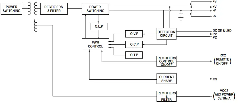 NMD-240 (Dual Output Module)
PWM fosc : 175KHz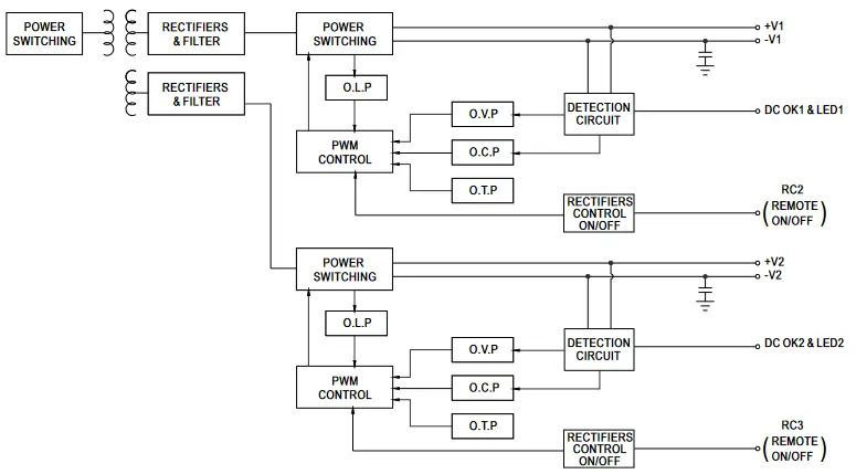 Derating Curve (NMP1K2, NMP650, NMS-240)
 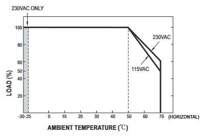 Static Characteristics
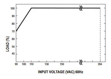 Derating Curve (NMD-240)
MECHANICAL SPECIFICATION
※ NMP1K2 (Front – End)
Case No.260A
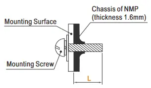
Unit:mm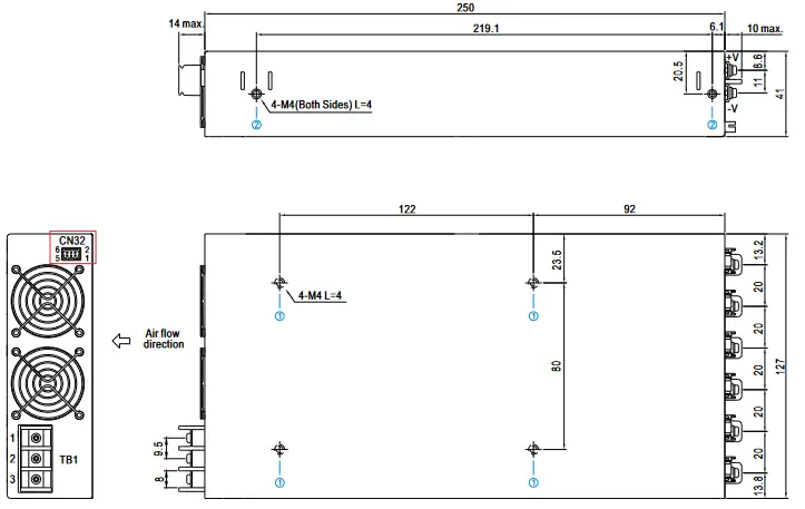 ※ Mounting Instruction
| Hole No. | Recommended Screw Size | MAX. Penetration Depth L | Recommended mounting torque |
| 1 | M4 | 4mm | 7-10Kgf-cm |
| 2 | M4 | 4mm | 7-10Kgf-cm |
 ※ AC Input Terminal Pin No. Assignment
| Pin No. | Assignment | Diagram | Screw Size | Maximum mounting torque |
| 1 | FG | 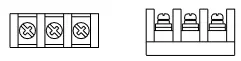 | M3.5 | 12Kgf-cm |
| 2 | AC/N | |||
| 3 | AC/L |
※ NMP650 (Front – End)
Case No.259A
Unit:mm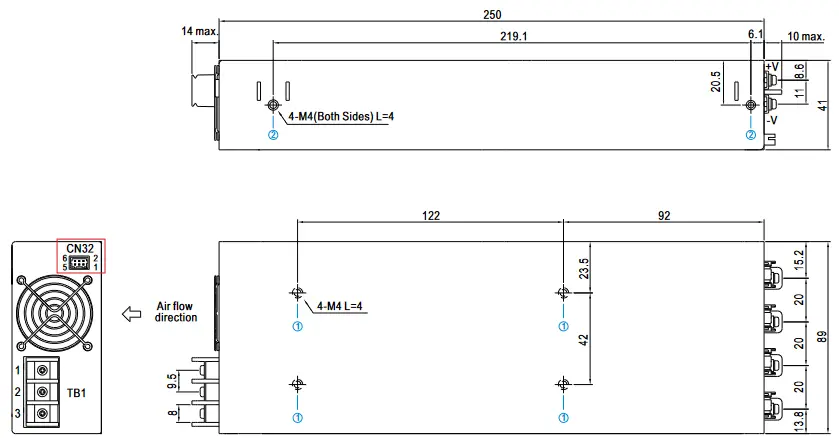
※ Mounting Instruction
| Hole No. | Recommended Screw Size | MAX. Penetration Depth L | Recommended mounting torque |
| 1 | M4 | 4mm | 7-10Kgf-cm |
| 2 | M4 | 4mm | 7-10Kgf-cm |
| Pin No. | Assignment | Diagram | Screw Size | Maximum mounting torque |
| 1 | FG | | M3.5 | 12Kgf-cm |
| 2 | AC/N | |||
| 3 | AC/L |
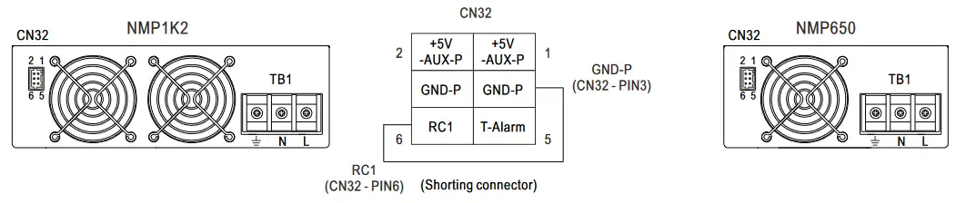
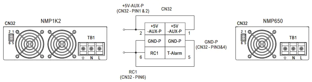
Function Description of CN32
※ Control Pin No. Assignment (CN32): HRS DF11-6DP-2DS or equivalent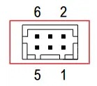
| Mating Housing | HRS DF11-6DS or equivalent |
| Terminal | HRS DF11-**SC or equivalent |
| Pin No. | Function | Description |
| 1, 2 | +5V-AUX_P | Auxiliary voltage output, 4.5-5.5V, referenced to pin 3 & 4 (GND-P). The maximum load current is 2A (NMP1 K2) or 1.5A (NMP650). |
| 3, 4 | GND-P | Ground. |
| 5 | T-Alarm | TTL signal output for over temperature alarm. The maximum sourcing current is 10mA. High(4.5-5.5V): When the internal temperature exceeds the limit & “safe limit” of temperature alarm. Low(0-0.5V): When the internal temperature is normal. |
| 6 | RC1 | Turns the output on and off by electrical or dry contact between pin 6 (RC1) and pin 3 & 4 (GND-P). Short: Power ON; Open: Power OFF. |
MECHANICAL SPECIFICATION
※ NMS-240 Single Output Module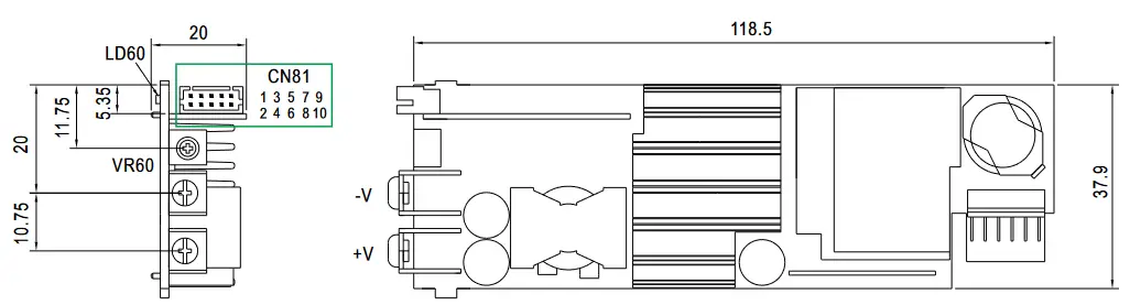 ※ Blank slot
Blank slot should be assembled with BLANK-NMS240, Please contact MEAN WELL for details.
※ DC Output Terminal Pin No. Assignment
| Assignment | Diagram | Maximum mounting torque | Recommended screw size | MAX. Penetration Depth L |
| +V, -V |  | 1 0Kgf-cm | M3.5 | 10mm |
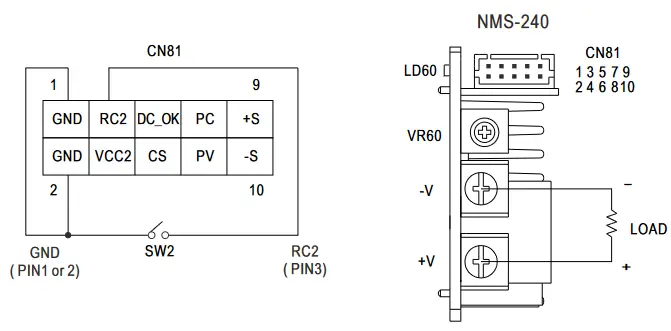
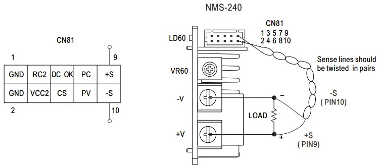
Function Description of CN81(NMS-240)
※ Control Pin No. Assignment (CN81): HRS DF11-10DP-2DS or equivalent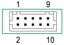
| Mating Housing | HRS DF11-10DS or equivalent |
| Terminal | HRS DF11-**SC or equivalent |
| Pin No. | Function | Description |
| 1 | GND | Ground. |
| 2 | GND | Ground. |
| 3 | RC2 | Turns the output on and off by electrical or dry contact between pin 3 (RC2) and pin 1&2 (GND). Open: Power ON; Short: Power OFF. |
| 4 | Vcc 2 | Auxiliary voltage output, 4.5-5.5V, referenced to pin 1 &2 (GND). The maximum load current is 10mA. |
| 5 | DC OK | “DC OK” signal is a TTL level, referenced to pin 1&2 (GND). Output modules turn on=4.5-5.5V, turn off=0-0.5V. The maximum sourcing current is 10mA (4.5-5.5V). |
| 6 | CS | Current sharing signal. When units are connected in parallel, the CS pins of the units should be connected to allow current balance between units. Referenced to pin 1&2 (GND) |
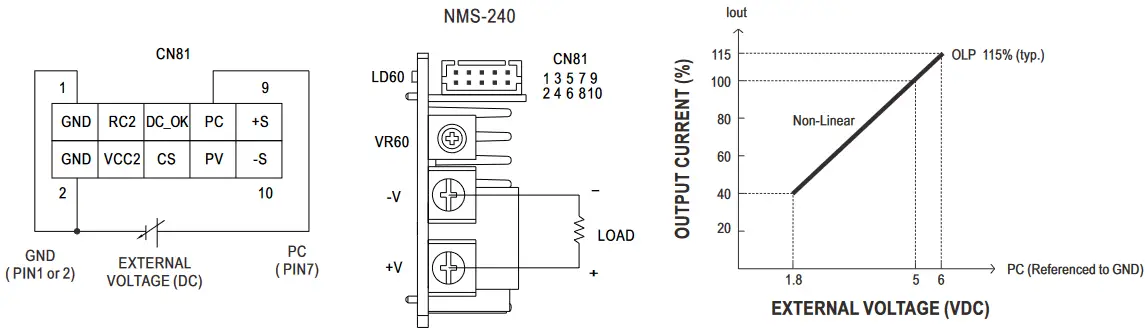
| 7 | PC | Connection for output current programming, referenced to pin 1&2 (GND) |
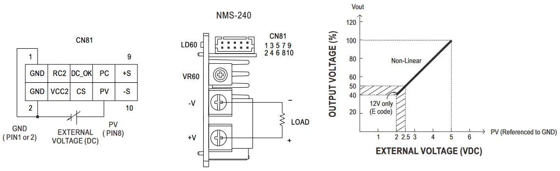
| 8 | PV | Connection for output voltage programming, referenced to pin 1 &2 (GND) |
| 9 | +S | Positive sensing for remote sense. |
| 10 | -S | Negative sensing for remote sense. |
※ NMD-240 Dual Output Module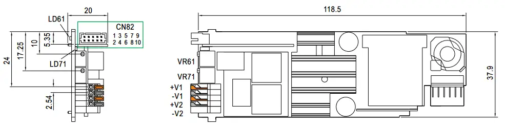
| Output number | Output voltage adjustable by SVR | LED display |
| V1 | 3-30V by VR61 | LD61 |
| V2 | 3-30V by VR71 | LD71 |
※ DC Output Terminal Pin No. Assignment
| Assignment | Color | Diagram | Wire range | Wire strip length |
| +V1 | Orange | 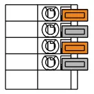 | 20-26AWG | 10mm |
| -V1 | Gray | |||
| +V2 | Orange | |||
| -V2 | Gray |
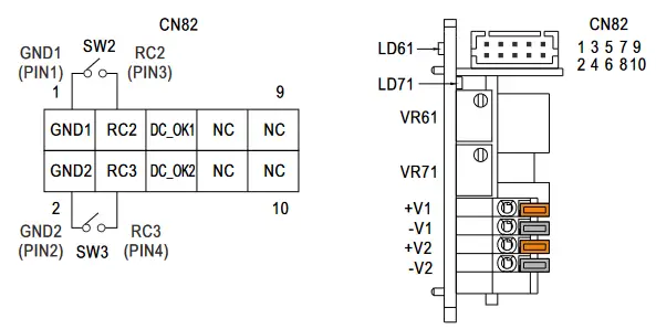
Function Description of CN82(NMD-240)
※ Control Pin No. Assignment (CN82): HRS DF11-10DP-2DS or equivalent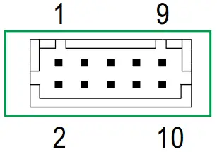
| Mating Housing | HRS DF11-10DS or equivalent |
| Terminal | HRS DF11-**SC or equivalent |
| Pin No. | Function | Description |
| 1 | GND1 | Ground(-V1). |
| 2 | GND2 | Ground(-V2). |
| 3 | RC2 | Turns the output V1 on and off by electrical or dry contact between pin 3 (RC2) and pin 1 (GND1). Open: Power ON; Short: Power OFF. |
| 4 | RC3 | Turns the output V2 on and off by electrical or dry contact between pin 4 (RC3) and pin 2 (GND2). Open: Power ON; Short: Power OFF. |
| 5 | DC OK1 | “DC OK1” signal is a TTL level, referenced to pin 1 (GND1). Output modules V1 turn on=4.5-5.5V, turn off=0-0.5V. The maximum sourcing current is 10mA (4.5-5.5V). |
| 6 | DC OK2 | “DC OK2” signal is a TTL level, referenced to pin 2 (GND2). Output modules V2 turn on=4.5-5.5V, turn off=0-0.5V. The maximum sourcing current is 10mA (4.5-5.5V). |
| 7,8,9,10 | NC | —- |
Function Manual
- “Global ON/OFF Control” function is not used
※ The power supply unit will have no output if the shorting connector (accessory comes along with the PSU) is not assembled. It contains one shorting wire: it is from RC1 (CN32 – PIN6) to GND-P (CN32 – PIN3)
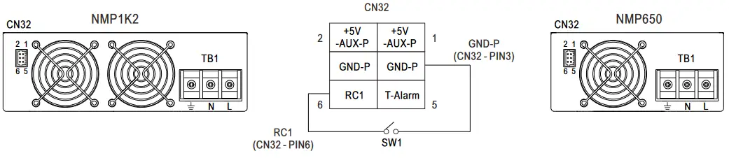
- lobal or Local ON/OFF CONTROL
※ The power supply can be turned ON/OFF for the entire unit, by global enable/inhibit, or for specific modules, by local Remote ON-OFF.
◎Global ON/OFFBetween RC1 (CN32-PIN6) and GND-P (CN32-PIN3) Output Status SW1 ON (short) ON SW1 OFF (open) OFF 
◎Local ON/OFF
The NMS-240 can be turned ON/OFF by using the ‘‘local ON/OFF’’ function.Between RC2 (CN81-PIN3) and GND (CN81-PIN1 or 2) Output Modules Status (NMS-240) SW2 OFF (open) ON SW2 ON (short) OFF 
◎Local ON/OFF
The NMD-240 can be turned ON/OFF by using the ‘‘local ON/OFF’’ function.Between RC2 (CN82-PIN3) and GND1 (CN82-PIN1) Output Modules Status (V1) SW2 OFF (open) Output V1 ON SW2 ON (short) Output V1 OFF Between RC2 (CN82-PIN3) and GND1 (CN82-PIN1) Output Modules Status (V2) SW2 OFF (open) Output V1 ON SW2 ON (short) Output V1 OFF 
- Remote Sense(NMS-240 only)
※ The Remote Sense compensates voltage drop on the load wiring up to 0.5V.
- Output Voltage Programming(PV : NMS-240 only)
※ In addition to the adjustment via the built-in potentiometer, the output voltage (default voltage set by VR60) can be trimmed by applying “EXTERNAL VOLTAGE”.
※ “Output Voltage Programming (PV)” range is the same as ‘‘Voltage ADJ. Range (VR60)”
- Constant Current Level Programming (PC : NMS-240 only)
※ The constant current level can be trimmed to 40~100% of the rated current by applying “EXTERNAL VOLTAGE”.
- Auxiliary Power
※+5V-Aux_P: Aux. power is 5V/2A(NMP1K2).
Aux. power is 5V/1.5A (NMP650). ※Vcc2: Aux. Power is 5V/10mA(Output Modules : NMS-240 only)
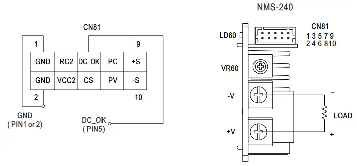
- DC OK Signal
“DC OK” signal is a TTL level signal. It indicates the output status of the output modules. “High” when module turns on.
The maximum sourcing current is 10mA (4.5~5.5V).
◎NMS-240Between DC OK (PIN5) and GND (PIN1 or 2) Output Modules Status (NMS-240) 4.5~5.5V ON 0~0.5V OFF  ◎NMD-240
Between DC OK1 (PIN5) and GND1 (PIN1) Output Modules Status (V1) 4.5~5.5V Output V1 ON 0~0.5V Output V1 OFF Between DC OK2 (PIN6) and GND2 (PIN2) Output Modules Status (V2) 4.5~5.5V Output V2 ON 0~0.5V Output V2 OFF 
- T-Alarm Signal
TTL signal output for over temperature alarm. The maximum sourcing current is 10mA.Between T-Alarm (CN32 PIN 5) and GND-P (CN32 PIN 3 or 4) Internal temperature (U702) Output Status 4.5~5.5V Exceeds the limit of temperature alarm. ON 4.5~5.5V Exceeds the “safe limit” of temperature alarm. ON 0~0.5V The internal temperature is normal. OFF 
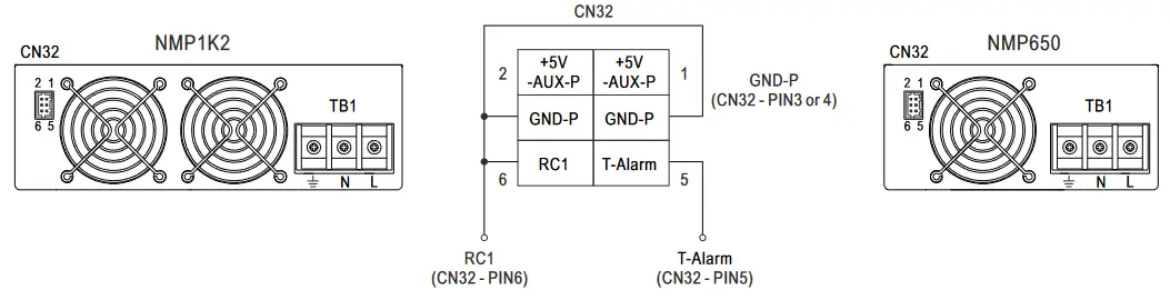
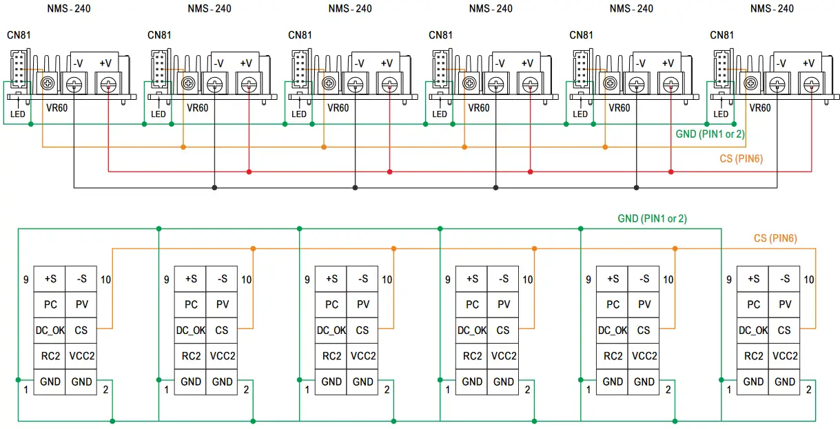
- CURRENT SHARING (CS : NMS-240 only)
(1) Parallel operation is available by connecting the NMS-240 shown as below (CS, GND are connected mutually in parallel).
(2) Difference of output voltages among parallel NMS-240 should be less than 0.2V.
(3) The total output current must not exceed the value determined by the following equation (Output current at parallel operation) = (The rated current per NMS-240) x (Number of NMS-240) ≦ TOTAL output power (NMP650 is 650W max.; NMP1K2 is 1200W max.) .
(4) In parallel operation 4 or 6 NMS-240 (NMP650 is 4 SLOTS; NMP1K2 is 6 SLOTS) is the maximum, please consult the manufacturer for other applications.
(5) The power supplies should be paralleled by using short and large diameter wiring and then connected to the load.
(6) In parallel connection, maybe only one NMS-240 (master) operates if the total output load is less than 10% of rated load condition. The other NMS-240 (slaves) may go into standby mode.
(7) NMS-240 * 6 SLOTS maximum (NMP1K2)、NMS-240 * 4 SLOTS maximum (NMP650).
(8) The short protection of C module (5V) or E module(12V) for current sharing is Hiccup mode or constant current limiting
(9) Remote control shall simultaneously turn ON/OFF all power modules that are in parallel. Per the same control logic, LED and DC OK signal of power modules in parallel shall turn ON/OFF simultaneously as well.
(10) When power modules are in parallel, output current programmable (PC) function shall NOT be in use.
※ Parallel or series connection accessory, please contact MEAN WELL for details.
 ※Vcc2: Aux. Power is 5V/10mA(Output Modules : NMS-240 only)
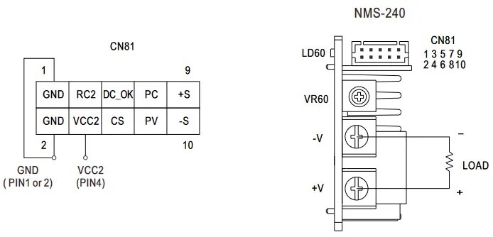
 ◎NMD-240
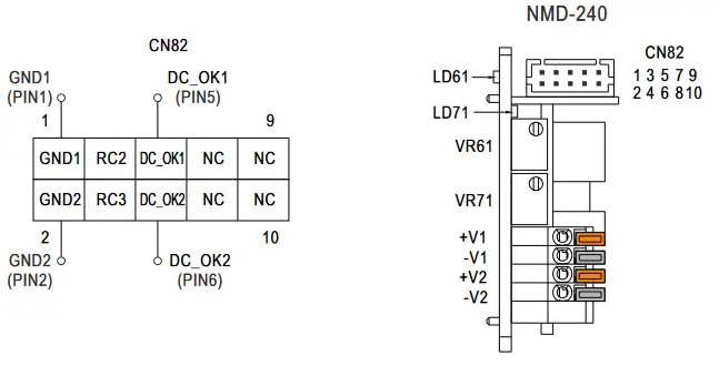
![]() File Name:NMP-SPEC 2022-08-08
File Name:NMP-SPEC 2022-08-08
Downloaded from Arrow.com.


