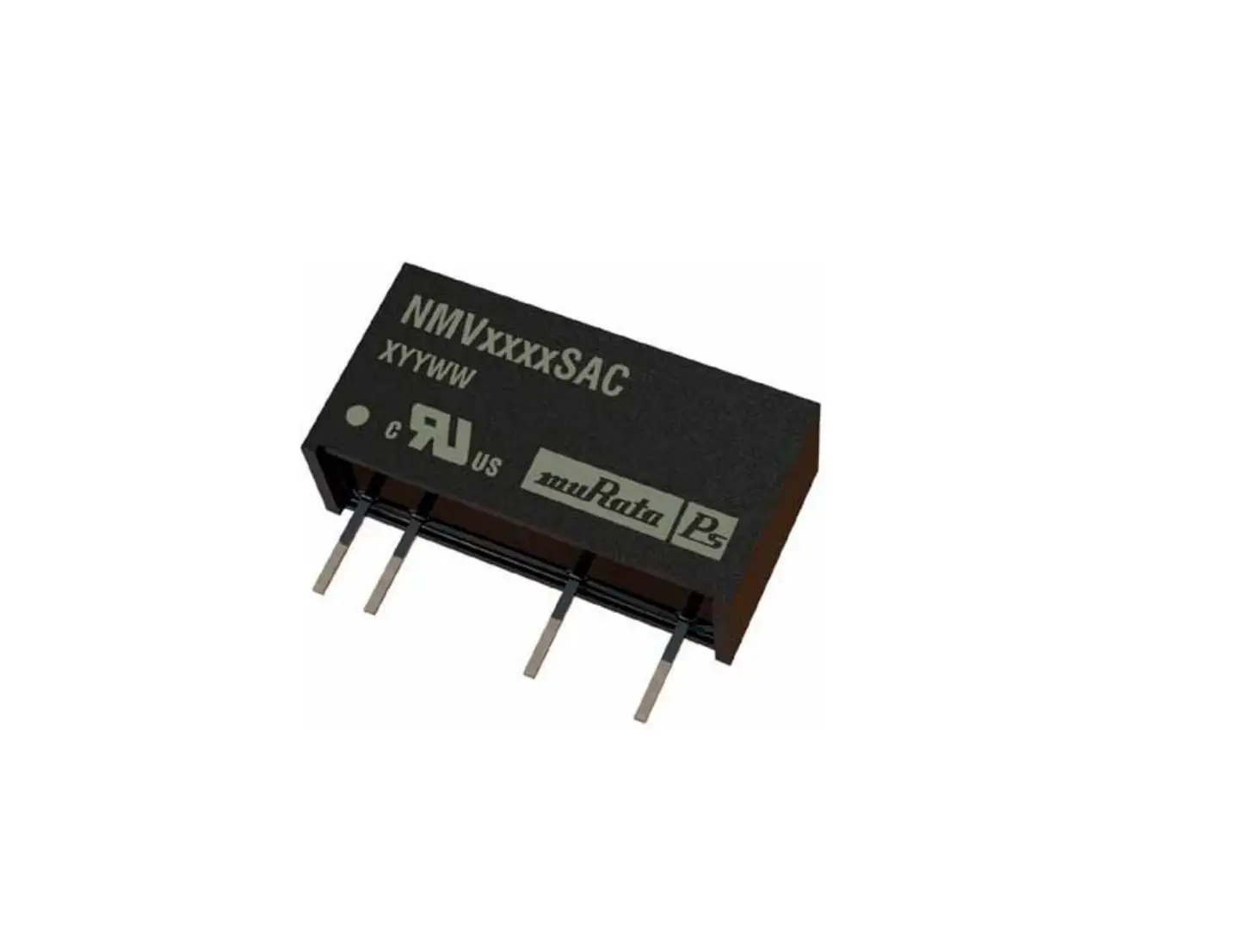
muRata NML0505SC Power Solutions Owner’s Manual
FEATURES
- Efficiency to 79%
- Wide temperature performance at full 1 Watt load, –40°C up to 105°C
- Single or dual outputs
- UL60950 recognised for functional insulation2
- Industry standard pinout
- Power sharing on dual outputs
- 3kVDC isolation (1 minute) ‘Hi-Pot Test’
- 5V, 12V & 15V inputs
- 5V, 9V, 12V & 15V outputs
- Internal SMD construction
- No external components required
- MTTF up to 4.2 million hours
- No electrolytic or tantalum capacitors
- Pin compatible with MEV1, MEV3 & NMK series
PRODUCT OVERVIEW
The NMV series of industrial temperature range DC-DC converters are the standard buliding blocks for on-board distributed power systems. They are ideally suited for providing local supplies on control system boards with the added benefit of 3kVDC galvanic isolation to reduce switching noise. Available in SIP and DIP with dual and single output pinout. All of the rated power may be drawn from a single pin provided the total load does not exceed 1 watt.
| SELECTION GUIDE | |||||||||||||
| Order Code | Nominal Input Voltage | Output Voltage | Output Current | Input Current at Rated Load | Load Regulation (Typ) | Load Regulation (Max) | Ripple & Noise (Typ) | Ripple & Noise (Max) | Efficiency | Isolation Capacitance | MTTF1 | Recommended Alternative | |
| V | V | mA | mA | % | mVp-p | % | pF | MIL. | Tel. | ||||
| kHrs | |||||||||||||
| Recommend In Production | |||||||||||||
| NMV0505DAC | 5 | 5 | 200 | 294 | 14.6 | 15 | 15 | 17 | 68 | 23 | 4241 | ||
| NMV0515DAC | 5 | 15 | 67 | 256 | 6.7 | 7.3 | 8.7 | 11 | 78 | 27 | 1838 | ||
| NMV0505SAC | 5 | 5 | 200 | 294 | 14.6 | 15 | 16 | 23 | 68 | 23 | 4241 | ||
| NMV0505TSAC | 5 | 5 | 200 | 240 | 7.7 | 10 | 20 | 40 | 74 | 30 | 3785 | 76148 | |
| NMV0509SAC | 5 | 9 | 111 | 267 | 9.3 | 10 | 12 | 15 | 75 | 30 | 3376 | ||
| NMV0512SAC | 5 | 12 | 84 | 260 | 7.4 | 8.0 | 11 | 15 | 77 | 26 | 2555 | ||
| NMV0515SAC | 5 | 15 | 67 | 256 | 6.7 | 7.3 | 11 | 14 | 78 | 27 | 1838 | ||
| NMV1205DAC | 12 | 5 | 200 | 121 | 14.6 | 15 | 9.5 | 14 | 69 | 26 | 2664 | ||
| NMV1205SAC | 12 | 5 | 200 | 121 | 14.6 | 15 | 11 | 16 | 69 | 26 | 2664 | ||
| NMV1212SAC | 12 | 12 | 84 | 108 | 7.4 | 8.0 | 9 | 22 | 77 | 43 | 1883 | ||
| NMV1215SAC | 12 | 15 | 67 | 108 | 6.7 | 7.3 | 8.5 | 17 | 77 | 42 | 1462 | ||
| NMV0505DC | 5 | ±5 | ±100 | 280 | 9.0 | 10 | 11 | 14 | 71.5 | 21 | 3106 | ||
| NMV0505SC | 5 | ±5 | ±100 | 280 | 9.0 | 10 | 11 | 17 | 71.5 | 21 | 3106 | ||
| NMV0512SC | 5 | ±12 | ±42 | 256 | 6.8 | 7.5 | 6.7 | 8 | 78 | 26 | 1579 | ||
| NMV0512TSC | 5 | ±12 | ±42 | 240 | 4.9 | 7 | 15 | 30 | 78 | 50 | 2655 | 11212 | |
| NMV0515SC | 5 | ±15 | ±33 | 253 | 6.8 | 8.5 | 6.3 | 8.2 | 79 | 27 | 1065 | ||
| NMV1215DC | 12 | ±15 | ±33 | 110 | 6.8 | 8.5 | 5.5 | 8 | 76 | 41 | 924 | ||
| NMV1212SC | 12 | ±12 | ±42 | 111 | 6.8 | 7.5 | 6 | 10 | 75 | 42 | 1287 | ||
| NMV1215SC | 12 | ±15 | ±33 | 110 | 6.8 | 8.5 | 6.5 | 13 | 76 | 41 | 924 | ||
| NMV1515SC | 15 | ±15 | ±33 | 84 | 2.3 | 3.0 | 7.5 | 9 | 77 | 84 | 522 | ||
| NMV0509DAC | 5 | 9 | 111 | 267 | 9.3 | 10 | 11.3 | 15 | 75 | 30 | 3376 | MEV1S0509SC | |
| NMV0509SC | 5 | ±9 | ±55 | 263 | 7.5 | 8.5 | 7 | 9.4 | 76 | 24 | 2258 | MEJ1D0509SC | |
| NMV0512DC | 5 | ±12 | ±42 | 256 | 6.8 | 7.5 | 6.7 | 9 | 78 | 26 | 1579 | MEJ1D0512SC | |
| NMV0515DC | 5 | ±15 | ±33 | 253 | 6.8 | 8.5 | 6 | 9 | 79 | 27 | 1065 | MEV1D0512SC | |
| NMV1205DC | 12 | ±5 | ±100 | 117 | 9.0 | 10 | 8.6 | 12 | 71 | 27 | 2148 | MEV1D1205SC | |
| NMV1205SC | 12 | ±5 | ±100 | 117 | 9.0 | 10 | 10 | 13 | 71 | 27 | 2148 | MEV1D1205SC | |
| NMV1209SAC | 12 | 9 | 111 | 113 | 9.3 | 10 | 7.5 | 14 | 74 | 35 | 2295 | MEV1S1209SC | |
| NMV1209SC | 12 | ±9 | ±55 | 113 | 7.5 | 8.5 | 8 | 11 | 74 | 35 | 1705 | MEJ1D1209SC | |
| NMV1212DAC | 12 | 12 | 84 | 108 | 7.4 | 8.0 | 8 | 19 | 77 | 43 | 1883 | MEV1S1212SC | |
| NMV1512SC | 15 | ±12 | ±42 | 87 | 2.6 | 3.0 | 7.5 | 9 | 75 | 68 | 789 | Contact Murata | |
| NMV1515SAC | 15 | 15 | 67 | 84 | 2.8 | 4.0 | 11 | 13 | 77 | 50 | 941 | MEV1S1515SC | |
| NMV0512DAC | 5 | 12 | 84 | 260 | 7.4 | 8.0 | 10.5 | 16 | 77 | 26 | 2555 | MEV1S0512DC | |
| NMV1209DAC | 12 | 9 | 111 | 113 | 9.3 | 10 | 7 | 8.5 | 74 | 35 | 2295 | MEV1S1209SC | |
| NMV1215DAC | 12 | 15 | 67 | 108 | 6.7 | 7.3 | 8 | 17 | 77 | 42 | 1462 | MEV1S1215DC | |
| NMV1505SAC | 15 | 5 | 200 | 93 | 8.3 | 10 | 15.5 | 17 | 67 | 21 | 2747 | MEV1S1505SC | |
| NMV1512SAC | 15 | 12 | 84 | 85 | 3.3 | 4.0 | 11.2 | 14 | 75 | 45 | 1365 | Contact Murata | |
| NMV0509DC | 5 | ±9 | ±55 | 263 | 7.5 | 8.5 | 7.5 | 9 | 76 | 24 | 2258 | NKA0509SC | |
| NMV1209DC | 12 | ±9 | ±55 | 113 | 7.5 | 8.5 | 6.5 | 9 | 74 | 35 | 1705 | NKA1209SC | |
| NMV1212DC | 12 | ±12 | ±42 | 111 | 6.8 | 7.5 | 6.2 | 8.5 | 75 | 42 | 1287 | MEV1D1212SC | |
| NMV1505SC | 15 | ±5 | ±100 | 91 | 5.5 | 10 | 11 | 12 | 69 | 39 | 1941 | Contact Murata | |
- Calculated using MIL-HDBK-217 FN2 and Telcordia SR-332 calculation model with nominal input voltage at full load.
- The NMV0505TSAC & NMV0512TSC are pending recognition to UL62368-1. All specifications typical at TA=25°C, nominal input voltage and rated output current unless otherwise specified.
| INPUT CHARACTERISTICS | |||||
| Parameter | Conditions | Min. | Typ. | Max. | Units |
| Voltage range | Continuous operation, 5V input types | 4.5 | 5 | 5.5 | V |
| Continuous operation, 12V input types | 10.8 | 12 | 13.2 | ||
| Continuous operation, 15V input types | 13.5 | 15 | 16.5 | ||
| Reflected ripple current | NMV0505TSAC & NMV0512TSC | 5 | mA p-p | ||
| All other output types | 20 | 40 | |||
| OUTPUT CHARACTERISTICS | ||||||
| Parameter | Conditions | Min. | Typ. | Max. | Units | |
| Rated Power | TA=-40°C to 120°C, see derating graph | 1 | W | |||
| Voltage Set Point Accuracy | See tolerance envelope | |||||
| Line regulation | High VIN to low VIN | All output types | 1.0 | 1.2 | %/% | |
| NMV0505TSAC & NMV0512TSC | 1.1 | 1.2 | ||||
| ISOLATION CHARACTERISTICS | |||||
| Parameter | Conditions | Min. | Typ. | Max. | Units |
| Isolation test voltage | Flash tested for 1 minute | 3000 | VDC | ||
| Resistance | Viso= 1000VDC | 10 | GΩ | ||
| GENERAL CHARACTERISTICS | |||||
| Parameter | Conditions | Min. | Typ. | Max. | Units |
| Switching frequency | NMV0505TSAC | 55 | kHz | ||
| NMV0512TSC | 60 | ||||
| 5V input types | 120 | 135 | |||
| 12V input types | 150 | 170 | |||
| 15V input types | 90 | 110 | |||
TECHNICAL NOTES
ISOLATION VOLTAGE
‘Hi Pot Test’, ‘Flash Tested’, ‘Withstand Voltage’, ‘Proof Voltage’, ‘Dielectric Withstand Voltage’ & ‘Isolation Test Voltage’ are all terms that relate to the same thing, a test voltage, applied for a specified time, across a component designed to provide electrical isolation, to verify the integrity of that isolation.
Murata Power Solutions NMV series of DC-DC converters are all 100% production tested at their stated isolation voltage. This is 3kVDC for 1 minute.
A question commonly asked is, “What is the continuous voltage that can be applied across the part in normal operation?”
The NMV has been recognized by Underwriters Laboratory for functional insulation, both input and output should normally be maintained within SELV limits i.e. less than 42.4V peak, or 60VDC. The isolation test voltage represents a measure of immunity to transient voltages and the part should never be used as an element of a safety isolation system. The part could be expected to function correctly with several hundred volts offset applied continuously across the isolation barrier; but then the circuitry on both sides of the barrier must be regarded as operating at an unsafe voltage and further isolation/insulation systems must form a barrier between these circuits and any user-accessible circuitry according to safety standard requirements.
REPEATED HIGH-VOLTAGE ISOLATION TESTING
It is well known that repeated high-voltage isolation testing of a barrier component can actually degrade isolation capability, to a lesser or greater degree depending on materials, construction and environment. The NMV series has toroidal isolation transformers, with no additional insulation between primary and secondary windings of enamelled wire. While parts can be expected to withstand several times the stated test voltage, the isolation capability does depend on the wire insulation. Any material, including this enamel (typically polyurethane) is susceptible to eventual chemical degradation when subject to very high applied voltages thus implying that the number of tests should be strictly limited. We therefore strongly advise against repeated high voltage isolation testing, but if it is absolutely required, that the voltage be reduced by 20% from specified test voltage.
This consideration equally applies to agency recognised parts rated for better than functional isolation where the wire enamel insulation is always supplemented by a further insulation system of physical spacing or barriers.
SAFETY APPROVAL
The NMV series has been recognised by Underwriters Laboratory (UL) to UL 60950 for functional insulation. The NMV0505TSAC & NMV0512TSC are pending recognition to UL62368-1.
The NMV Series of converters are not internally fused so to meet the requirements of UL 60950 an anti surge input line fuse should always be used with ratings as defined below.
NMV05xxxxC: 0.5A
NMV12xxxxC: 0.2A
NMV15xxxxC: 0.2A
All fuses should be UL recognised and rated to at least the maximum allowable DC input voltage. File number E151252 applies.
RoHS COMPLIANCE INFORMATION
This series is compatible with RoHS soldering systems with a peak wave solder temperature of
260°C for 10 seconds. Please refer to application notes for further information. The pin termination
finish on the SIP package type is Tin Plate, Hot Dipped over Matte Tin with Nickel Prelate. The DIP
types are Matte Tin over Nickel Prelate. Both types in this series are backward compatible with Sn/
Pb soldering systems.
For further information, please visit www.murata-ps.com/rohs
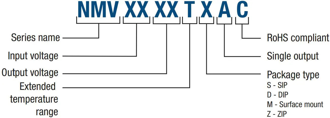
PART NUMBER STRUCTURE
CHARACTERISATION TEST METHODS
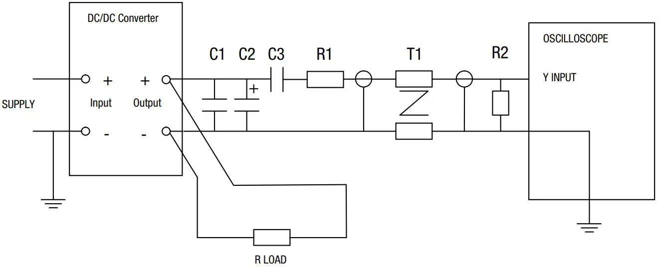
Ripple & Noise Characterisation Method
Ripple and noise measurements are performed with the following test configuration.
| C1 | 1μF X7R multilayer ceramic capacitor, voltage rating to be a minimum of 3 times the output voltage of the DC-DC converter |
| C2 | 10μF tantalum capacitor, voltage rating to be a minimum of 1.5 times the output voltage of the DC-DC converter with an ESR of less than 100mΩ at 100 kHz |
| C3 | 100nF multilayer ceramic capacitor, general purpose |
| R1 | 450Ω resistor, carbon film, ±1% tolerance |
| R2 | 50Ω BNC termination |
| T1 | 3T of the coax cable through a ferrite toroid |
| RLOAD | Resistive load to the maximum power rating of the DC-DC converter. Connections should be made via twisted wires |
| Measured values are multiplied by 10 to obtain the specified values. | |
Differential Mode Noise Test Schematic
APPLICATION NOTES
Minimum load
The minimum load to meet datasheet specification is 10% of the full rated load across the specified input voltage range. Lower than 10% minimum loading will result in an increase in output voltage, which may rise to typically double the specified output voltage if the output load falls to less than 5%.
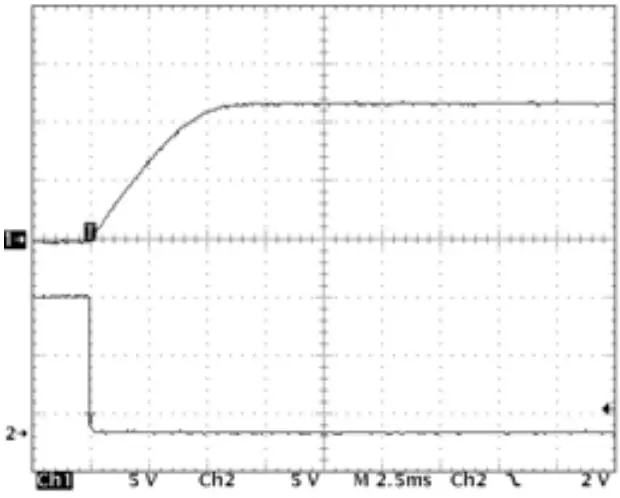
Capacitive loading and start up
Typical start up times for this series, with a typical input voltage rise time of 2.2μs and output capacitance of 10μF, are shown in the table below. The product series will start into a capacitance of 47μF with an increased start time, however, the maximum recommended output capacitance is 10μF.
| Start-up time | |
| μs | |
| NMV0505TSAC | 215 |
| NMV0505xC | 1966 |
| NMV0509xC | 5360 |
| NMV0512xC | 11180 |
| NMV0515xC | 16270 |
| NMV0512TSC | 2300 |
| NMV1205xC | 1290 |
| Start-up time | |
| μs | |
| NMV1209xC | 4140 |
| NMV1212xC | 8650 |
| NMV1215xC | 11171 |
| NMV1505xC | 803 |
| NMV1512xC | 3510 |
| NMV1515xC | 8361 |
APPLICATION NOTES (Continued)
Output Ripple Reduction
By using the values of inductance and capacitance stated, the output ripple at the rated load is lowered to 5mV p-p max.
Component selection Capacitor: It is required that the ESR (Equivalent Series Resistance) should be as low as possible, ceramic types are recommended.
The voltage rating should be at least twice (except for 15V output), the rated output voltage of the DC-DC converter.
Inductor: The rated current of the inductor should not be less than that of the output of the DC-DC converter. At the rated current, the DC resistance of the
inductor should be such that the voltage drop across the inductor is <2% of the rated voltage of the DC-DC converter. The SRF (Self Resonant Frequency) should be >20MHz.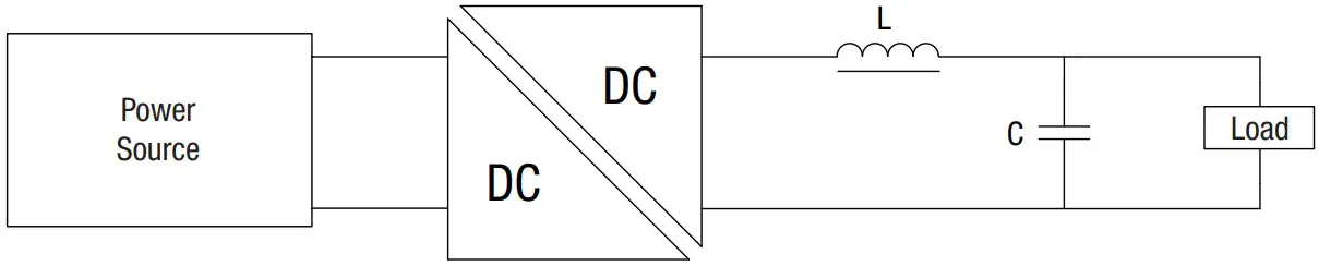
| Inductor | Capacitor | |||||||
| L, μH | SMD | Through Hole | C, μF | |||||
| NMV0505TSAC | 22 | 84223C | 11R223C | 22 | ||||
| NMV0505xC | 22 | 82223C | 11R223C | 1 | ||||
| NMV0509xC | 100 | 82104C | 11R104C | 0.47 | ||||
| NMV0512TSC | 10 | 82103C | 11R103C | 22 | ||||
| NMV0512xC | 150 | 82154C | 11R154C | 0.33 | ||||
| NMV0515xC | 220 | 82224C | 11R224C | 0.22 | ||||
| NMV1205xC | 22 | 82223C | 11R223C | 2.2 | ||||
| NMV1209xC | 100 | 82104C | 11R104C | 1 | ||||
| NMV1212xC | 150 | 82154C | 11R154C | 0.33 | ||||
| NMV1215xC | 220 | 82224C | 11R224C | 0.22 | ||||
| NMV1505xC | 22 | 82223C | 11R223C | 1 | ||||
| NMV1512xC | 150 | 82154C | 11R154C | 0.33 | ||||
| NMV1515xC | 220 | 82224C | 11R224C | 0.22 | ||||
TOLERANCE ENVELOPES
The voltage tolerance envelope shows typical load regulation characteristics for this product series. The tolerance envelope is the maximum output voltage variation due to changes in output loading
NMV0505TSAC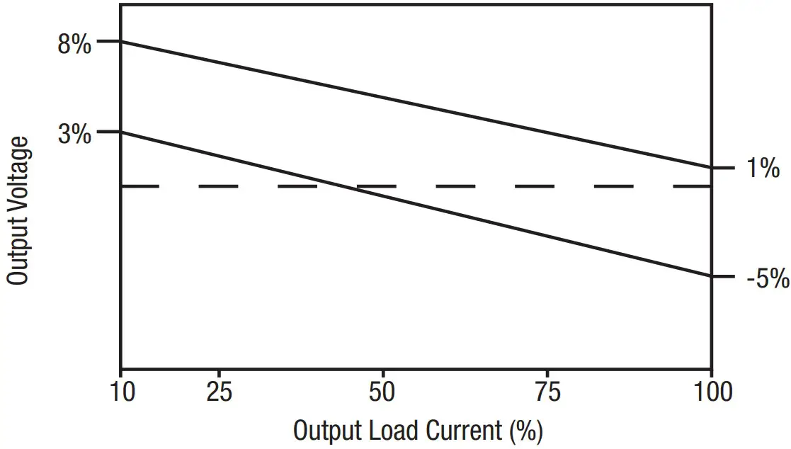
TEMPERATURE DERATING GRAPH
NMV0505TSAC & NMV0512TSC: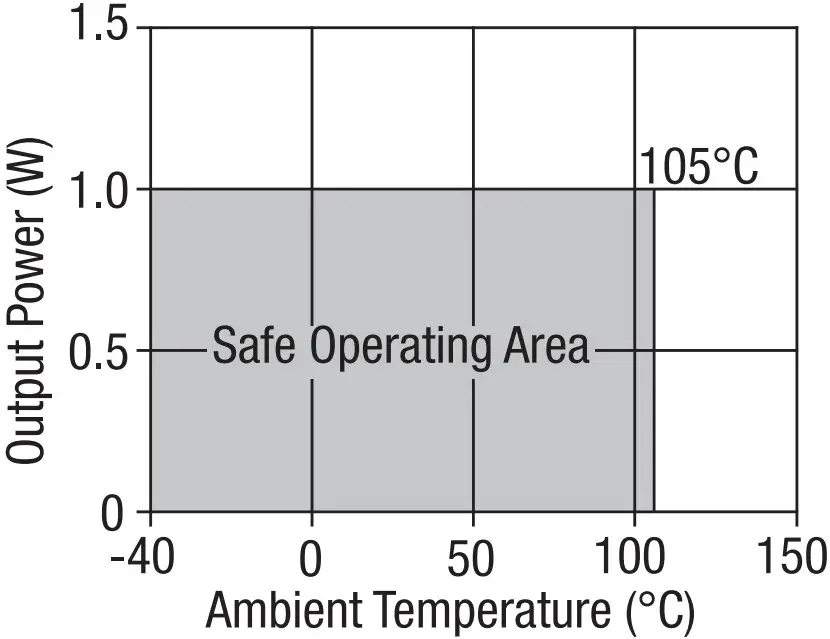
All other variants:
PACKAGE SPECIFICATIONS
MECHANICAL DIMENSIONS
SIP package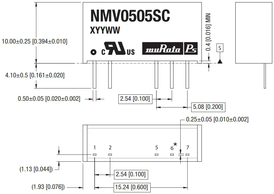
All dimensions in mm (inches). Controlling dimension is mm.
All pins on a 2.54 (0.100) pitch and within ±0.1 (0.004) of true position from pin 1 at seating plane ‘S
RECOMMENDED FOOTPRINT DETAILS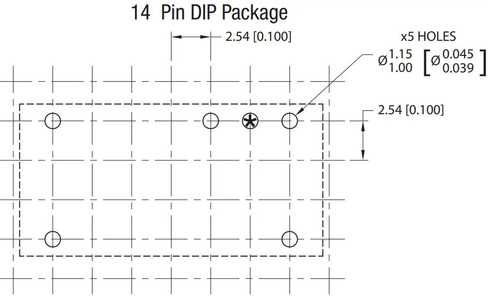
Unless otherwise stated all dimensions in mm (inches) ±0.5mm.
PIN CONNECTIONS – 4 PIN SIP
| 14 Pin DIP | |
| Pin | Function |
| 1 | -VIN |
| 7 | NC |
| 8 | +VOUT |
| 10 | -VOUT |
| 14 | +VIN |
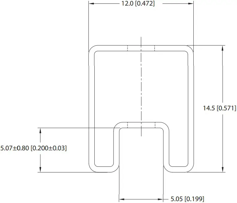
Unless otherwise specified all dimensions in mm [inches] ±0.55mm [0.022].
Tube Length : 520mm [20.472] ±2.0 [0.079].
Dual output variants
DISCLAIMER
Unless otherwise stated in the datasheet, all products are designed for standard commercial and industrial applications and NOT for safety-critical and/or life-critical
applications.
Particularly for safety-critical and/or life-critical applications, i.e. applications that may directly endanger or cause the loss of life, inflict bodily harm and/or loss or severe damage to equipment/property, and severely harm the environment, a prior explicit written approval from Murata is strictly required. Any use of Murata standard products for any safety-critical, life-critical or any related applications without any prior explicit written approval from Murata shall be deemed unauthorised use.
These applications include but are not limited to:
- Aircraft equipment
- Aerospace equipment
- Undersea equipment
- Power plant control equipment
- Medical equipment
- Transportation equipment ( automobiles, trains, ships, etc.)
- Traffic signal equipment
- Disaster prevention / crime prevention equipment
- Data Processing equipment
Murata makes no express or implied warranty, representation, or guarantee of suitability, fitness for any particular use/purpose and/or compatibility with any application or device of the buyer, nor does Murata assume any liability whatsoever arising out of unauthorised use of any Murata product for the application of the buyer. The suitability, fitness for any particular use/purpose and/or compatibility of Murata product with any application or device of the buyer remain to be the responsibility and liability of the buyer.
Buyer represents and agrees that it has all the necessary expertise to create and implement safeguards that anticipate dangerous consequences of failures, monitor failures and their consequences, lessen the likelihood of failures that might cause harm, and take appropriate remedial actions. Buyer will fully indemnify and hold Murata, its affiliated companies, and its representatives harmless against any damages arising out of unauthorised use of any Murata products in any safety-critical and/ or life-critical applications.
Remark: Murata in this section refers to Murata Manufacturing Company and its affiliated companies worldwide including, but not limited to, Murata Power Solutions
![]() This product is subject to the following operating requirements
This product is subject to the following operating requirements
and the Life and Safety Critical Application Sales Policy:
Refer to: https://www.murata.com/en-eu/products/power/requirements
Murata Power Solutions (Milton Keynes) Ltd. makes no representation that the use of its products in the circuits described herein, or the use of other technical information contained herein, will not infringe upon existing or future patent rights. The descriptions contained herein do not imply the granting of licenses to make, use, or sell equipment constructed in accordance therewith. Specifications are subject to change without notice.
© 2022 Murata Power Solutions (Milton Keynes) Ltd
www.murata.com
Downloaded from Arrow.com


