![]()
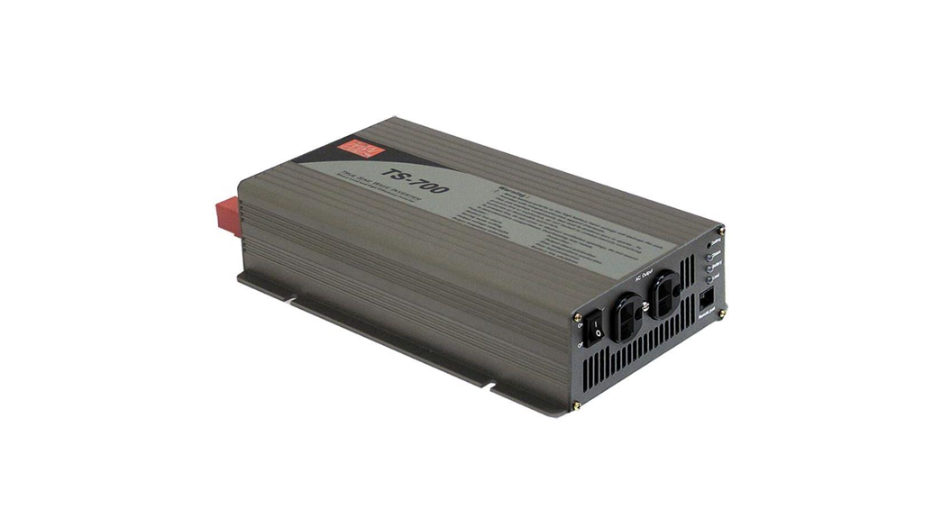
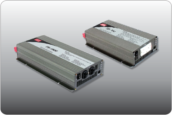 TS-700/1000
Inverter Instruction Manual
Safety Guidelines
(Please read through this manual before assembling TS700/1000)
- Risk of electrical shock and energy hazard. All failures should be examined by a qualified technician. Please do not remove the case of the inverter by yourself!
- Please do not install the inverter in places with high moisture or near water.
- Please do not install the inverter in places with high ambient temperature, under direct sunlight, or near a flame source.
- Please only connect batteries with the same brand and model number in one battery bank. Using batteries from different manufacturers or different capacities is strictly prohibited!
- Never allow a spark or flame in the vicinity of the batteries because it may generate explosive gases during normal operation.
- Make sure the airflow from the fan is not obstructed at both sides (front and back) of the inverter. Please allow at least 15cm of space.
- Please do not stack any object on the inverter.
- This device complies with part 15 of the FCC Rules. Operation is subject to the following two conditions:
(a) This device may not cause harmful interference, and
(b) this device must accept any interference received, including interference that may cause undesired operation.
![]() WARNING:
WARNING:
Batteries will have an aging problem after years of operation. It is suggested to execute regular battery maintenance (e.g. every year). Once aged, the batteries should be changed by a professional technician, or the failed batteries may cause fire or other hazards.
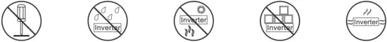 | ||||
| Don’t disassemble | Away from moisture | Away from fire or high temperature | Don’t stack on the inverter | Keep good ventilation |
WARNING: This is a class A product. In a domestic environment, this product may cause radio interference in which case the user may be required to take adequate measures.
Introduction
- Fully digital controlled by an advanced CPU, TS-700/1000 is a true sine wave DC/AC Inverter, Drawing power from the battery bank and converting it into AC voltage.
- With pure sine wave output, TS-1000 can provide 1000W continuously, 1150W for 3 minutes, and surge power of 2000W. (TS-700 can provide 700W continuously, 800W for 3 minutes, and surge power 1400W.) General applications include PC, ITE, vehicles, yachts, home appliances, motors, power tools, industrial control equipment, AV systems and etc…
2.1 Features
- True sine wave output (THD < 3.0% )
- 700W / 1000W rated output
- High efficiency up to 92%
- Complete LED indication for operation status
- Battery low alarm and indicator
- Output voltage / Frequency selectable
- Fully digital controlled including monitoring & display
- Compliance to UL458(only TS-1000) / FCC / E13/ CE
- Can be used for most electronic products with AC input
- 3 years global warranty
2.2 Main Specification
TS-700
| Model | 112 | 124 | 148 | 212 | 224 | 248 | |
| O U T P U T | Rated power | 700W max. continuously, 800W max. for 180 seconds, 1050W max. for 10 seconds | |||||
| 1400W (30cycles) | |||||||
| AC voltage | 110Vac, 60Hz (Factory setting) | 230Vac, 50Hz (Factory setting) | |||||
| 100/110/115/120Vac (Selectable by setting button) | 200/220/230/240Vac (Selectable by setting button) | ||||||
| 50/60Hz (Selectable by setting button) | |||||||
| Waveform | True sine wave (THD <3.0%) at rated input voltage | ||||||
| Protection | AC short • Overload • Over Temperature | ||||||
| I N P U T | Bat. voltage range | 10.5 | 21.0 | 42.0 | 10.5 | 21.0 | 42.0 |
| DC current | 75A | 38A | 19A | 75A | 38A | 19A | |
| Efficiency | 86% | 88% | 89% | 89% | 90% | 91% | |
| Off mode current draw | Under 1.0mA at power switch OFF | ||||||
| Protection | Overcurrent • battery polarity reverse by fuse • battery low shutdown • battery low alarm | ||||||
TS-1000
| Model | 112 | 124 | 148 | 1212 | 224 | 248 | |
| O U T P U T | Rated power | 1000W max. continuously, 1150W max. for 180 seconds, 1500W max. for 10 seconds | |||||
| 2000W (30cycles) | |||||||
| AC voltage | 110Vac, 60Hz (Factory setting) | 230Vac, 50Hz (Factory setting) | |||||
| 100/110/115/120Vac (Selectable by setting button) | 200/220/230/240Vac (Selectable by setting button) | ||||||
| 50/60Hz (Selectable by setting button) | |||||||
| Waveform | True sine wave (THD <3.0%) at rated input voltage | ||||||
| Protection | AC short • Overload • Over Temperature | ||||||
| I N P U T | Bat. voltage range | 10.5 | 21.0 | 42.0 | 10.5 | 21.0 | 42.0 |
| DC current | 100A | 50A | 25A | 100A | 50A | 25A | |
| Efficiency | 88% | 89% | 90% | 90% | 91% | 92% | |
| Off mode current draw | Under 1.0mA at power switch OFF | ||||||
| Protection | Overcurrent • battery polarity reverse by fuse • battery low shutdown • battery low alarm | ||||||
User Interface
3.1 Front PanelA.POWER ON/OFF switch: The inverter will turn OFF if the switch is in the OFF position.B. AC output outlet: For the application demands of different geographic areas all over the world, there are many different kinds of optional AC outlets to choose from.C. Ventilation holes: The inverter requires suitable ventilation to work properly. Please make sure there is good ventilation and the lifespan of the inverter can be preserved.D. Function Setting: Output voltage, frequency, and saving mode can be set through this button.E. LED Indicating Panel: Operating status, battery status, load condition, and all kinds of warnings will be displayed on this panel.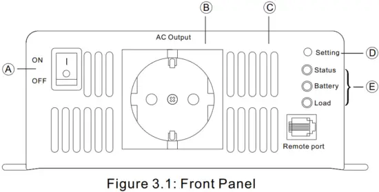 3.2 LED Indicator on Front Panel
Status LED: Represents the current operating status
| LED color | Green | Orange | Red |
| Status | Normal | Saving mode | Abnormal |
*Note: Refer to section 5.2 for an explanation of the abnormal status
Battery LED: Represents the remaining capacity of external batteries
| LED color | Green | Orange | Red |
| Battery capacity | >70% | 40 ~ 70% | <40% |
LOAD LED: Represents the magnitude of output load
| LED color | Green | Orange | Red |
| Load percentage | <50% | 50 ~ 80% | >80% |
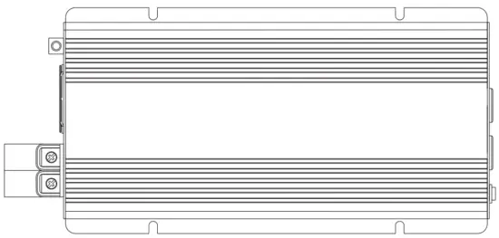
Rear Panel
. Battery input (+),(-)B. Fan ventilation openingC. Frame ground (FG)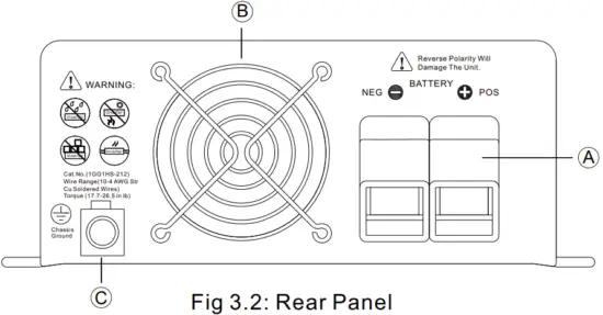
Setup (Output Voltage, Frequency, and Saving Mode)
4.1 Initial State
The initial state is set to110Vac/60Hz or 230Vac/50Hz and disabled “Saving Mode” is activated. If users need to revise it for certain applications, it can be done with the setting button on the front panel (Please refer to section 4.2). The unit will start up automatically after the setting procedure is finished and the new settings will be executed. These new settings will be kept even if the unit is powered off/on for any reason.
4.2 Procedure of Setting up Output Voltage, Frequency, and Saving Mode
STEP 1: The inverter should be turned off while resetting. Input batteries should be connected and the loads should be removed.
STEP 2: Use an insulated stick to press the setting button and then turn on the power switch. Orange led indication will flash ON and OFF. after pressing for 5 seconds, the inverter will send out a “Beep” sound. Users can release the button and go into the setting procedure.
STEP 3: Please refer to Table 4-1 and check whether the combination of output voltage and frequency is the one you need. If yes, please jump to STEP 5. If not, start from STEP 4.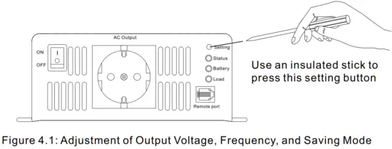 Table 4-1: LED Indication of Output Voltage / Frequency Combination
| Output Voltage | 100Vac (200Vac) | 110Vac (220Vac) | 115Vac (230Vac) | 120Vac (240Vac) | |
| Frequency | |||||
| 50Hz | Status | ||||
| Battery | |||||
| Load | |||||
| 60Hz | Status | ||||
| Battery | |||||
| Load | |||||
![]() Light
Light![]() Dark
Dark![]() Flashing
Flashing
Note: The above indication will be shown in green
STEP 4: The LEDs will change state each time you press the setting button for 1 second and then release (refer to Figure 4.2). Please select the suitable combination of output voltage and frequency you need.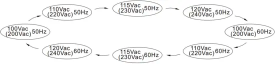 Figure 4.2: State Circulation Diagram of Output Voltage and Frequency
STEP 5: After selecting the output voltage and frequency, press the setting button for 3~5 seconds and the inverter will send out a “Beep” sound. The button can be released and it goes into the setting section of “Saving Mode”.
STEP 6: Please refer to Table 4-2 and check whether the “Saving Mode” is already set as you desired. If yes, please jump to STEP 8. If not, start from STEP 7.
Table 4-2: LED Indication of Saving Mode Selection
| Saving Mode ON | Status | |
| Battery | ||
| Load | ||
| Saving Mode OFF | Status | |
| Battery | ||
| Load |
Note: The above indication will be shown in green
![]() Light
Light![]() Dark
Dark![]() Flashing
Flashing
STEP 7: The LEDs will change state each time you press the setting button for 1 second and then release. Please activate or cancel the “Saving Mode” function as desired.
STEP 8: After activating or canceling the “Saving Mode”, press the setting button for around 5 seconds and the inverter will send out a “Beep” sound. The button can be released and all the settings are finished. The inverter will automatically store all the settings and start to operate.
Protection
5.1 Input Protection
(A)Battery Polarity Protection: If the battery input is connected in reverse polarity, the internal fuse of the inverter would blow and the inverter should be sent back to MEAN WELL for repair.
(B)Battery Under Voltage Protection: When the battery voltage is lower than the preset value, the inverter will automatically terminate the output thus protecting the battery from damage. Please refer to Table 5-1 for more detail about the failure signals.
(C)Battery Over Voltage Protection: When the battery voltage is too high, the inverter will automatically terminate the output providing and the built-in buzzer will be activated to inform the users. Please refer to Table 6.1 for more detail about the failure signals.
![]() WARNING:
WARNING:
Please choose suitable batteries that are compatible with the rated input DC voltage of TS-700/1000 (refer to the SPEC). If the input DC voltage is too low (ex. using a 12Vdc battery bank for 24Vdc input models), TS-700/1000 can not be started up properly. If the input DC voltage is too high (ex. using a 48Vdc battery bank for 24Vdc input models), TS-700/1000 will be damaged!
5.2 Output Protection
The display panel will show failure status when the inverter is faced with abnormal operating conditions (refer to Table 5-1). This lets the user know what could be the problem.
- OTP: When the internal temperature is higher than the limit value, the “Over Temperature Protection” will be activated. The unit will automatically turn off and should be restarted again.
- AC output abnormal protection: When the AC output voltage of the inverter is too high or too low, the unit will turn off and should be restarted again.
- AC output short circuit protection: When a short circuit situation occurs at the output side of the inverter or the loads increase greatly in a short period of time, the unit will turn off and should be restarted again.
- Battery voltage abnormal protection: When the battery voltage is too high or too low, this protection will be activated. The inverter will auto recover after the battery voltage go back to a safe level and users do not need to restart it.
- OLP: When the output is overloaded between 735~800W(TS- 700)/1050~1150W(TS-1000), the inverter can still continuously provide power for 3 minutes. After that, if the overload condition is not removed, overload protection will activate. When the load is higher than 1050W(TS700)/1500W(TS-1000), the overload protection will be activated instantly.
For these overload protections, once activated, the unit must reset to recover.
Table 5-1: Failure Messages On Front Panel
| Failure Message | LED Indicator | Failure Message | LED Indicator |
| Output Overload (105-115% load) |
| Abnormal AC Output Voltage | |
| Output Overload (115-150% load) | AC Output Short Circuit | ||
| Output Overload (150% load) | Abnormal Battery Voltage | ||
| Over Temperature |
| LED Status |
Note: The above indication will be shown in red
Installation & Wiring
(A)Wiring for Batteries: Wire connections should be as short as possible and less than 1.5 meters is highly recommended. Make sure that suitable wires are chosen based on the rating of current. Too small of a cross-section will result in overheating that could induce certain danger. Please refer to Table 6-1 and consult our local distributors if you have any questions.
Table 6-1: Suggestions for Wire Selection
| Equipment (Amp) | Cross-section of Lead (mm² ) | AWG | Suggested wiring |
| 16A ~ 25A | 2.5 | 12 | Model using 48V battery |
| 25A ~ 32A | 4 | 10 | |
| 32A ~ 40A | 6 | 8 | |
| 40A ~ 63A | 10 | 6 | Model using 24V battery |
| 63A ~ 80A | 16 | 4 | |
| 80A ~ 100A | 25 | 2 | Model using 12V battery |
| 100A ~ 125A | 35 | 1 | |
| ≧125A | 50 | 0 |
(B)Suggested battery type and capacity
| Battery type | Lead-acid battery | |||||
| Battery Capacity | 112 | 212 | 124 | 224 | 148 | 248 |
| 12V / 120Ah ~ 12V / 400Ah | 24V / 60Ah ~ 24V / 200Ah | 48V / 30Ah ~ 48V / 100Ah | ||||
(C)Requirement of Installation:
The unit should be mounted on a flat surface or holding rack with suitable strength. In order to ensure the lifespan of the unit, please refrain from operating in an environment of high dust or high moisture. This is a power supply with a built-in DC fan. Please make sure that ventilation is not blocked. There should be no barriers within 15cm of the ventilating holes.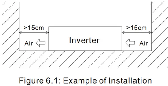
(D)Mounting Suggestion :
There is 4 semi-circular cutout on the side flanges of the inverter. It can be used for fixing TS-700/1000 onto the system enclosure.
We high recommend mounting in the horizontal position. Please make sure ventilation openings are free from obstruction.
 (E)Example of system diagram
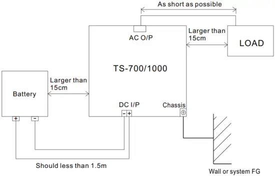
Where the installation of the DC input and chassis grounding is shown below :
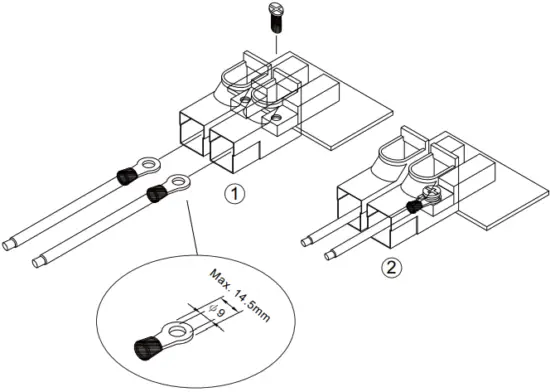 Cat. No. (1GG1HS-191)
Rating (150A )
Suitable cables (cables with 75℃ temperature rating, connected with ring terminal)
Torque (32~106.2 in-lbs)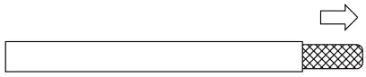 Cat.No.(1GG1HS-212)
Suitable wires (10-4 AWG tinned copper wires)
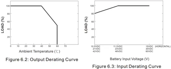
Torque (17.7-26.5 in-lbs)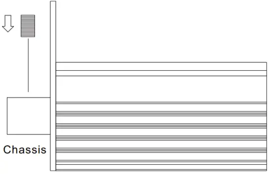 (F)Derating
 (G)
(G) ![]() Notes on output load:
Notes on output load:
TS-700/1000 Series can power most of the equipment that needs an AC source that can provide 700W(TS-700)/1000W(TS-1000) continuously. But for certain load types, the unit may not work properly.
- Since inductive loads or motor-based equipment need a large start-up current (6~10 times its rated current), the inverter may not start up successfully with these kinds of loads.
- When the output is capacitive or rectified equipment (such as switching power supply), it is suggested to operate this equipment at no load or light load. To ensure proper operation, you should increase the loads only after TS-700/1000 has started up.
Failure Correction Notes
TS-700/1000 should be serviced by a professional technician. Any improper usage or modification may damage the unit or result in a shock hazard. If you are not able to clear the failure condition, please contact Mean WELL or any of our distributors for repair service.
| Status | Possible Reasons | Ways to Eliminate |
| No AC output voltage | Abnormal input | Check the AC or DC input sources. Make sure the voltage is within the required range. |
| Over-temperature protection | Make sure that the ventilation is not blocked or that the ambient temperature is too high. Please derating the output usage or reducing the ambient temperature. | |
| Overload protection | Make sure the output load does not exceed the rated value or that the instantaneous start-up current is not too high. (for inductive or capacitive loads) | |
| Short circuit protection | Make sure the output is not overloaded or short-circuited | |
| Discharging period of batteries is too short | Batteries are aged or broken | Replace the batteries |
| The battery capacity is too small | Reconfirm the specification and enlarge the battery capacity as suggested | |
| The fan does not spin | Clog with foreign bodies | Remove the foreign objects |
| Malfunction of the fan | Repair required. Please send it back to us or any of our distributors |
Warranty
Three years of global warranty is provided for TS-700/1000 under normal operating conditions. Please do not change components or modify the unit by yourself or MEAN WELL may reserve the right not to provide the complete warranty.
MEAN WELL ENTERPRISES CO., LTD.
No.28, Wuquan 3rd Rd., Wugu Dist., New Taipei City 248, Taiwan
Te1:886-2-2299-6100
http://vvvvw.meanwell.com
Fax:886-2-2299-6200
E-mail:[email protected]
Your Reliable Power Partner


