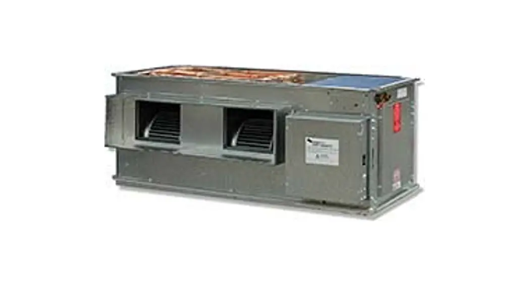
![]() IMDL 40Y (c/w EC motor)
IMDL 40Y (c/w EC motor)
Instruction Manual
Ducted Fan Coil Units
 Note:
Note:
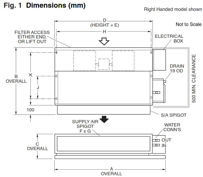
- Allow adequate clearance for the filter (if fitted) to be removed.
- IMDL 130 has two half-length filters, 2 motors, and 3 fans.
- Left-handed models have drain exit nearer the supply air side.
| WATER CONN’S BSP MALE | ||||||||||||
| MODEL | A | B | C | D | E | F | GHJKCOLDHOT | |||||
| IMDL 40Y | 685 | 715 | 255 | 550 | 245 | 512 | 170 | 526 | 225 | 470 | 20 | 13 |
| IMDL 60Y | 940 | 715 | 255 | 795 | 245 | 762 | 170 | 775 | 225 | 470 | 20 | 13 |
| IMDL 90Y | 1195 | 750 | 265 | 1050 | 255 | 1012 | 179 | 1026 | 265 | 510 | 25 | 13 |
| IMDL 130Y | 1595 | 750 | 265 | 1450 | 255 | 1412 | 179 | 1427 | 265 | 510 | 25 | 13 |
NOTE
The manufacturer reserves the right to change specifications at any time without notice or obligation. Certified dimensions are available on request.
Installation & Maintenance
GENERAL
The IMDL-Y ducted fan coil units must be installed in accordance with all national and local safety codes.
Optional
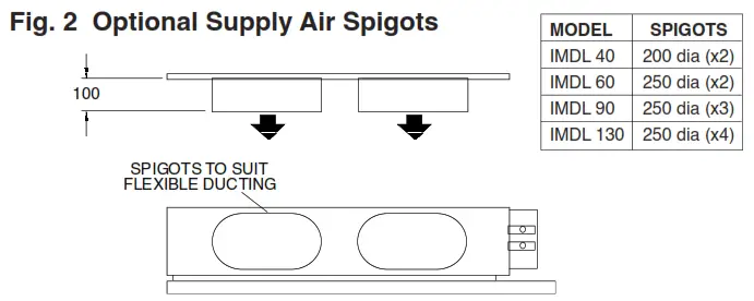
- Supply air spigot adaptors (refer to Fig.2).
- Flexible hoses:
– 13 BSP (1/2″) part no. 060-000-270
– 20 BSP (3/4″) part no. 060-000-271
– 25 BSP (1″) part no. 060-000-272. - Electric heater elements (factory fitted).
INSTALLATION
Positioning & Mounting
Provide 500 mm minimum clearance to the electrical box end of the unit.
Allow adequate clearance for the filter to be withdrawn to its full length from either end of the unit. Alternatively, the filter may be lifted out of its track.
Left-handed models have a drain exit on the supply air side of the drain tray.
Install the unit suspended on threaded rods or bolts and locking nuts (not supplied). Alternatively, mount each unit on vibration isolators on a suitable platform.
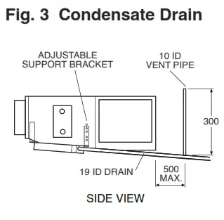
The unit must be installed level. Use the adjustable support bracket (see figure 3) to lower the drain pipe outlet and provide a slope in the drain tray.
WATER SUPPLY & RETURN
The IMDL unit’s IN and OUT water connections are male pipe threaded (refer to Fig. 1).
Warning: overtightening of connections to the main water supply may damage the unit.
It is recommended you use two temper zone 600 mm flexible high-pressure water hoses. These have female pipe threaded connections at each end. The maximum water pressure for each hose is 1720 kPa (250 psi). The IMDL unit alone, excluding hoses, will withstand 4480 kPa (650 psi).
Poor quality water supply must be prefiltered and it is essential that adequate water treatment is maintained, particularly where open cooling towers are used.
Condensate Drain
The drain should have a slope of at least 1 in 50 and must not be piped to a level above the unit drain tray. Fit a vent pipe within 500 mm of the unit (see Fig.3). Check the drain by pouring water into the drain tray and ensuring that it clears.
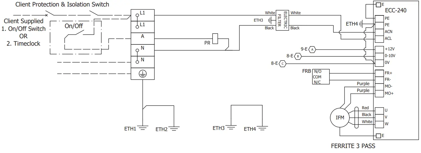
ELECTRICAL WIRING
Electrical work must be carried out by a qualified electrician in accordance with local supply authority regulations and the wiring diagram.
The electrical supply required is:
1 phase 230V a.c. 50Hz with neutral and earth. A lockable motor-rated isolator switch shall be fitted as close as possible to the unit. Refer to wiring diagrams for max. operating current.
Wire the unit directly from the electrical distribution board. The unit shall have its own dedicated circuit breaker on the Distribution Board.
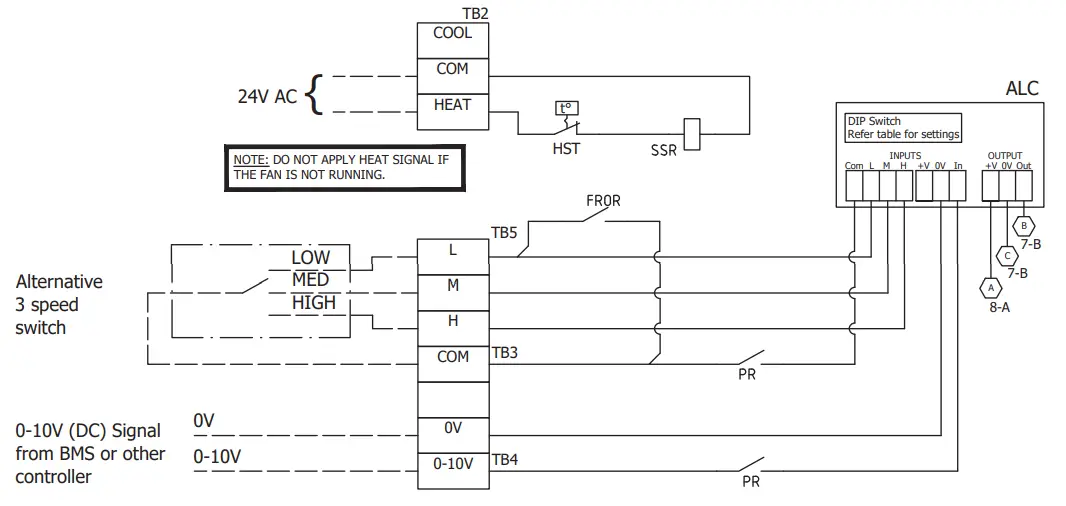
Units with Electric Heat: A 24V ac externally sourced power connection is required to control the optional electric heater elements via the solid state relay (SSR); refer to wiring diagram (page 4).
FAN CONTROL
Overview
The fan can be controlled between selectable low and high levels using either:
- 0–10V DC control voltage (ie continuously variable), or
- (up to) 3 contact inputs (ie stepped).
Only one control method must be connected at any one time; not both.
fan run-on is provided with durations suiting water sourced and electric heating systems.
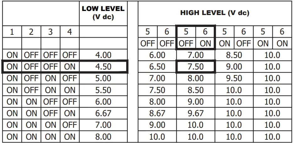
Control Levels (Output Voltages) DIP switches 1-4 of the Analog Level Controller (ALC on wiring schematics) select the low fan control voltage level. DIP switches 5 and 6 select the high fan control voltage level as a set amount above the low level.
The medium-level setting is halfway between the low and high setting levels.
The control voltage settings apply to both 0-10V and contact input control levels.
Refer to the wiring schematic diagram for the default settings and the available level settings.
Contact Inputs
Voltage-free contact inputs can be used to operate the fan at the selected control levels.
0-10V Input
A 0–10V DC signal can be used to control the fan. The fan is stopped for input signals below 1.6V. The fan operates at the selected low level when the input signal is between 1.6 and 2.0V. As the input signal increases above 2V the fan control signal increases linearly reaching the selected high level when the input signal is 10V. Note: Minimum control voltage is 4V for units with electric heat.
Run-On
The run-on duration is selected with DIP switch 8 for either 40 seconds or 120 seconds for electric heating systems. If electric heating is fitted ensure DIP switch 8 is set on for 120 seconds run-on.
The fan will run on for the selected period when the 0–10V input falls below 1.6V and all the contact inputs are opened. If the 0–10V input signal remains below 1.6V and the contact inputs remain open the fan will stop at the end of the run-on period.
Note: Select fan control levels that avoid water carry-over problems.
ELECTRIC HEAT (Option)
Units installed with electric heat elements include both auto (90°C) and manual (120°C) high temp. safety thermostats. If the manual high temp. safety t/stat requires resetting and the auto high temp. safety t/stat does not reset, then the latter needs to be replaced.
Note: The minimum control voltage is raised to 4V to ensure adequate heat dissipation from the electric elements.
COMMISSIONING
- Check that the thermostat is correctly wired and set at the desired temperature.
- Check that the air filter is clean.
- Check that the fan runs freely without vibration.
- Check the condensate drain for free drainage.
MAINTENANCE
Weekly For First Four Weeks
1. Check the air filter; vacuum clean as necessary.
2. Check the condensate drain for free drainage.
Monthly
Check air filter; vacuum clean as necessary.
Six Monthly
- Check the condensate drain for free drainage.
- Check heat exchanger coil; vacuum or brush clean as necessary.
- Check the tightness of the fan.
- Check that the fan motor is free running.
- Check the tightness of electrical connections.
- Check air supply at diffuser outlets.
NOTE
The manufacturer reserves the right to change specifications at any time without notice or obligation. Certified dimensions are available on request.
Standard Unit
ALC DIP Switch Settings
FACTORY SETTING ![]()
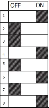 | ||
| DO NOT USE | LEAVE ON | |
| Lowest Speed Setting | 4.5V (4V – 8V) | |
| Highest Speed Setting | 7.5V (6 – 10V) | |
| LEAVE OFF | DO NOT USE | |
| DO NOT USE | LEAVE ON (120s Fan run on) |
Fan Control Voltage Output Setting and Range DIP Sw. options
ONLY USE DIP SWITCH SETTING COMBINATIONS PUBLISHED IN THE TABLES
Lowest Speed Setting DIP Switch 1 to 4 (LOW)
Highest Speed Setting DIP Switch 5 and DIP 6 (HIGH) With the 3-speed control the medium (MED) level is always halfway between HIGH and LOW levels.
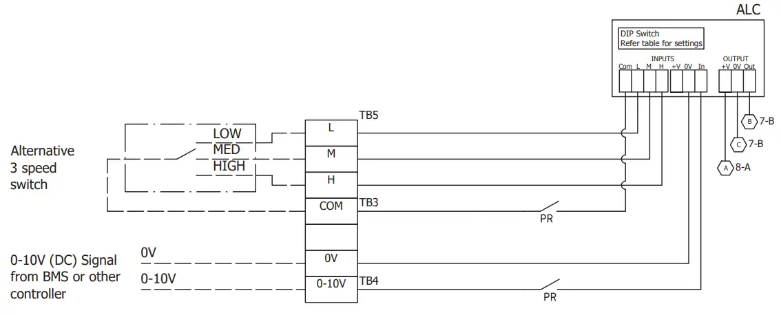
NOTE: Do NOT connect BOTH 3-speed L/M/H switch and also 0-10V (DC) signal.
Only ONE control method may be connected at a time. If in doubt ask!
| ALC | Analogue Level Controller |
| EHC | Electric Heat Contactor |
| FROM | Fan Run On Relay |
| HE | Heater Element |
| PR | Power Relay |
| ETH | Earth Stud |
| REV | MODIFICATION | DATE | ECN | APVD |
| A | Initial release. | 13-12-21 | ECN 5016 | S.S. |
| ©temperzone Ltd 2021 | Client Wiring | Drawn: S.S. | Date: 13/12/21 | Title: IMDL 40Y-SPE Electrical Wiring Schematic | Drawing No: 291-003-481 SHEET 1 OF 1 | Rev: A |
| Approved: | ||||||
Standard Unit c/w Electric Heat & SSR
ALC DIP Switch Settings
FACTORY SETTING ![]()
| ||
| DO NOT USE | LEAVE ON | |
| Lowest Speed Setting | 4.5V (4V – 8V) | |
| Highest Speed Setting | 7.5V (6 – 10V) | |
| LEAVE OFF | DO NOT USE | |
| DO NOT USE | LEAVE ON (120s Fan run on) |
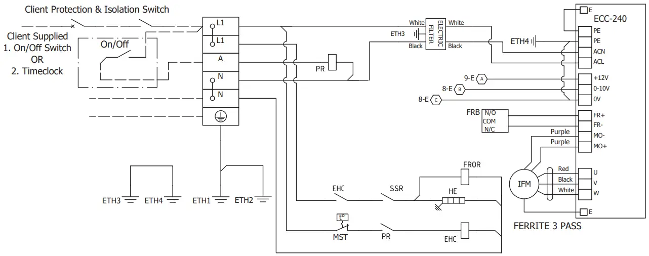
Fan Control Voltage Output Setting and Range DIP Sw. options
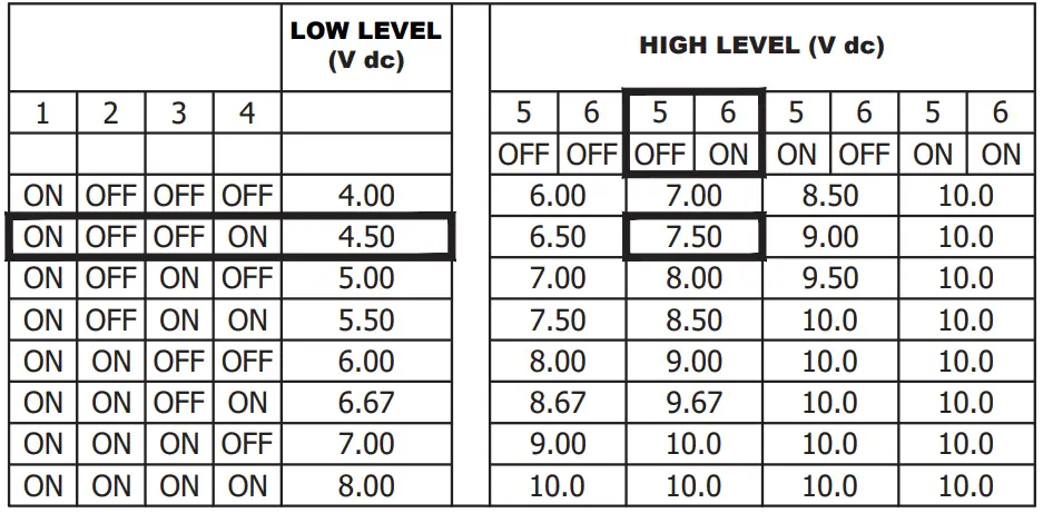
ONLY USE DIP SWITCH SETTING COMBINATIONS PUBLISHED IN THE TABLES
Lowest Speed Setting DIP Switch 1 to 4 (LOW)
Highest Speed Setting DIP Switch 5 and DIP 6 (HIGH) With the 3-speed control the medium (MED) level is always halfway between HIGH and LOW levels.
NOTE: Do NOT connect BOTH 3-speed L/M/H switch and also 0-10V (DC) signal.
Only ONE control method may be connected at a time.
If in doubt ask!
| ALC | Analogue Level Controller |
| EHC | Electric Heat Contactor |
| FROR | Fan Run On Relay |
| HE | Heater Element |
| HST | Auto High Temp. T/Stat |
| MST | Manual High Temp. T/Stat |
| PR | Power Relay |
| SSR | Solid State Relay |
| ETH | Earth Stud |
| REV | MODIFICATION | DATE | ECN | APVD |
| A | Initial release. | 13-12-21 | ECN 5016 | S.D.H. |
| ©temperzone Ltd 2021 | Client Wiring | Drawn: S.D.H. | Date: 13/12/21 | Title: IMDL 40Y-SPE EH c/w SSR Electrical Wiring Schematic | Drawing No: 291-003-480 SHEET 1 OF 1 | Rev: A |
| Approved: | ||||||
© temper zone limited 2022


