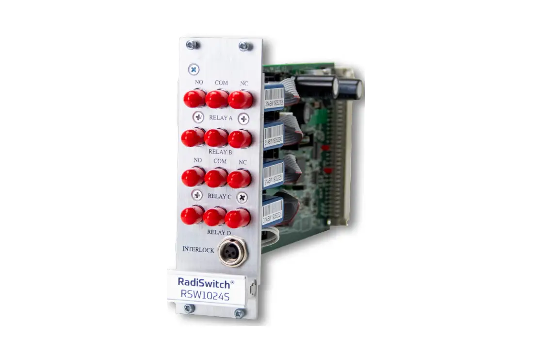
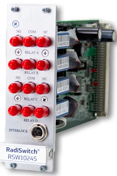
raditeq RGN2006A RadiSwitch Coaxial Relay Switch Cards
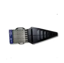
Connectors of the RadiSwitch®
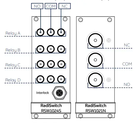
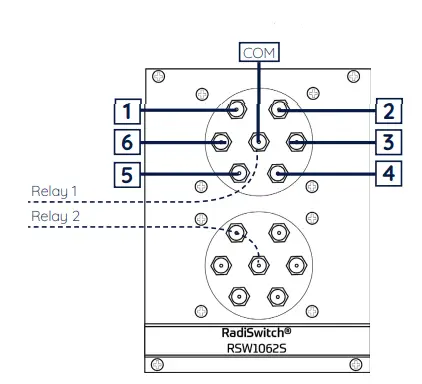
The RadiSwitch® is available in a wide variety of models with different types of connectors. The figures below defines all connector types and their differences. This quick start guide also describes the connections of each connector type. For more detailed information on the connector types and all RadiSwitch® related functions please refer to the RadiSwitch® Manual. All Raditeq manuals can be found at: www.raditeq.com/raditeq-downloads
SPDT (x4) SPDT (x1)
SP6T (x2)
Phoenix connector
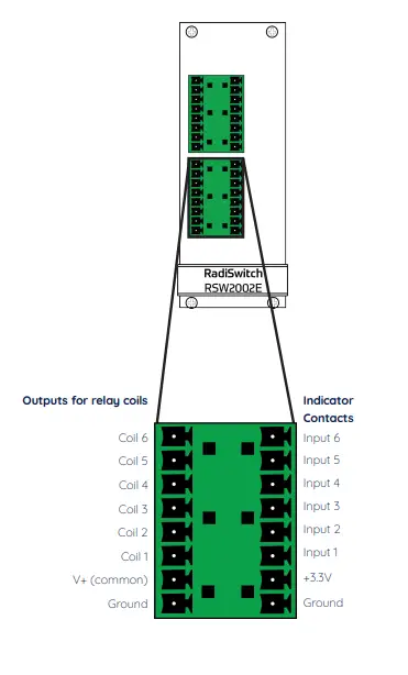
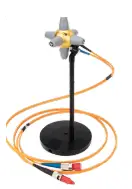
Connect (RF) cables
After the observing the difference between the models and selecting the applicable RadiSwitch® model connect all needed (RF) cables accordingly.
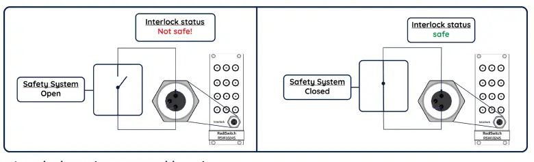
Interlock status & safety system
Some models of the RadiSwitch® are equipped with an interlock. This interlock can be connected with a safety system. Some systems and setups require a safety system which can be controlled by the RadiSwitch®. When the safety system detects a hazardous situation the interlock of the RadiSwitch® will be triggerd an set all selected relays to their NC position (normally clossed).
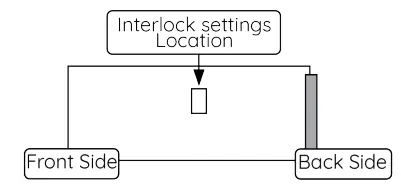
Interlock settings general location
All relays can be indepentantly activated and deactivated to work with the inerlock (safety system). The location of the interlock safety settings selector in the figure below.
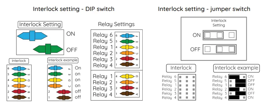
Interlock settings
The interlock settings can be changed as shown below. There are two types of interlock settings, the DIP switch and the Jumper switch.
NOTE: The DIP switch has numbering on the left side of the casing. Be aware that these numbers do not correspond to the same number of relay. Always use the relay settings stated below to set the correct relay.
Manual Control
- Press the ‘status’ box to enter the control screen for an overview of the relay positions.
- Press the buttons next to the relay to change the relay position.
- Press ‘Config’ to enter the device configuration screen for more detailed configuration.
- In case of a failure, an error will be displayed in the screen.
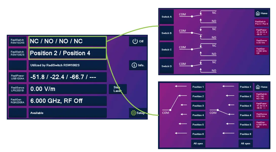
NOTE:
Depending on model, the display shows either one, two or four relays. Any external relay will be shown as a SP6T x2.
Additional information
More information can be found in the RadiSwitch® manuals which can be downloaded at: https://www.raditeq.com/raditeq-downloads/
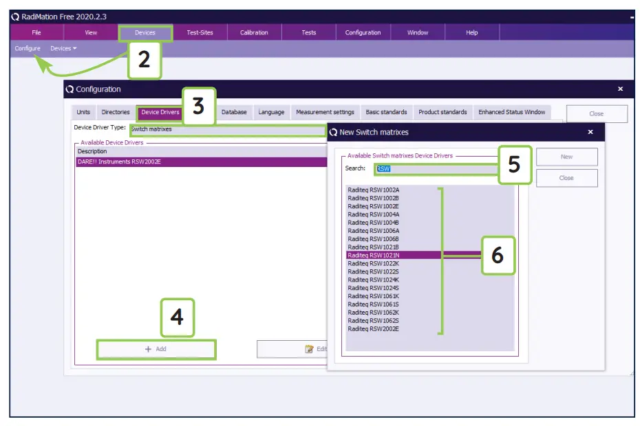
How to configure the RadiSwitch® in RadiMation®
- Start the latest version of RadiMation®; Download the latest version at: https://www.raditeq.com/radimation-download/
- Select the button ‘Device’ at the top menu bar, followed by clicking ‘Configure’;
- In the configuration screen select ‘Device Drivers’ and Select ‘Switch matrix’ as driver type;
- Click the ‘Add’ button to open the selection of available drivers in RadiMation®;
- Enter ‘RSW’ in the search bar which will show all available RadiSwitch® drivers;
- Select the correct driver, double click it (Optional, rename it) and press ‘OK’.
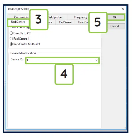
How to connect the RadiSwitch® to the RadiCentre®
- Select the recently added RadiSwitch® driver
- Select ‘Advanced’
- Click on the tab ‘RadiCentre®’
- Under device identification select the RadiCentre® slot number the RadiSwitch® plug-in card is installed in
- When the correct slot number is chosen, continue to set the communication of the RadiSwitch® by clicking ‘Ok’
How to check if the RadiSwitch® is connected to RadiMation
In order to utilize the RadiMation® software to its fullest capabilities ensure that the latest RadiMation® software version is installed. Additionally, confirm that all equipment is correctly connected and turned ON.
- Select ‘Devices’ in the top menu bar
- Open ‘Device Drivers’ and select device driver type: ‘Switch Matrix’
- Double Click the recently configured RadiSwitch® or click ‘edit’.
- Finally select the ‘check’ button on the right side of the opened screen.
- When correctly configured RadiMation® will notify you that the device was installed correctly.
Important information
When you need support with the configuration of your Radi-Product in RadiMation®, please consult the RadiMation® support team at: [email protected]. It is also advised to visit the RadiMation® Wiki page and the FAQ section, which can be found at: https://wiki.radimation.com RadiMation® software can be downloaded at: https://www.raditeq.com/emc-test-software/radimation-download
- Read the contents of this product manual carefully and become familiar with the safety markings, the product instructions and the handling of the system. Please refer to the applicable product manual(s) for further information regarding the operation and control of the product(s).
- To increase the safety of immunity test systems, some of our RadiSwitch cards are equipped with an additional interlock function, which is designed to work with our modular RadiCentre® systems.
- This product contains no hazardous substances as described in the RoHS Directive (2015/863/EU).
- This equipment is designed to be used as a plug-in card for the RadiCentre® series. Do not use this card on its own or in combination with any other mainframe. Using this product with any other mainframe can cause harm and will void warranty.
- Only Raditeq qualified maintenance personnel is allowed to perform maintenance and/or repair service on the equipment.
- This product requires a protective earth connection. The mains power source for the equipment must supply an uninterrupted safety ground to the IEC input connector(s).
- This product contains embedded software, which is field upgradeable from the RadiCentre® using the USB-A connection port on the backside panel of the RadiCentre®. For more information about updating your Raditeq plug-in card, please read the RadiCentre® manual.
Please keep this Quick Start Guide close at hand when you operate your Raditeq equipment and instruments. For more information, please consult your product manual or visit www.raditeq.com Be advised that visuals used as an example and may differ from your product version. Copyright © 2008 – 2021 Raditeq B.V.
Optimize your EMC test system
Configure your fully automated EMC test system with the extensive range of Raditeq products For more information about Raditeq’s EMC and RF products, visit our website at www.raditeq.com
Raditeq Featured products
Automated EMC & RF software ![]()
Electric Field Probes
Electric Field Generators
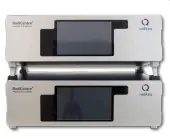
Modular test systems
For all Manuals, Datasheets and Quick start Guides, please visit: www.raditeq.com/support/downloads


