![]()
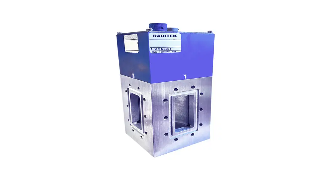
Waveguide Switch SPDT, 8.2-12.4 GHz
WR90, Flange Option, x Volts option
WR90 Waveguide Switch
WR90 WG SWITCH, xVDC, x FLANGE, -SPDT
| Voltage Options | AMPS |
| +22 To +32 | 0.9 |
| -22 To -32 | 0.9 |
| +10 To +14 | 1.5 |
| -10 To -14 | 1.5 |
| +44 To +54 | 0.5 |
| -44 To -54 | 0.5 |
| 117VAC | 0.5 |
| 235VAC | 0.5 |
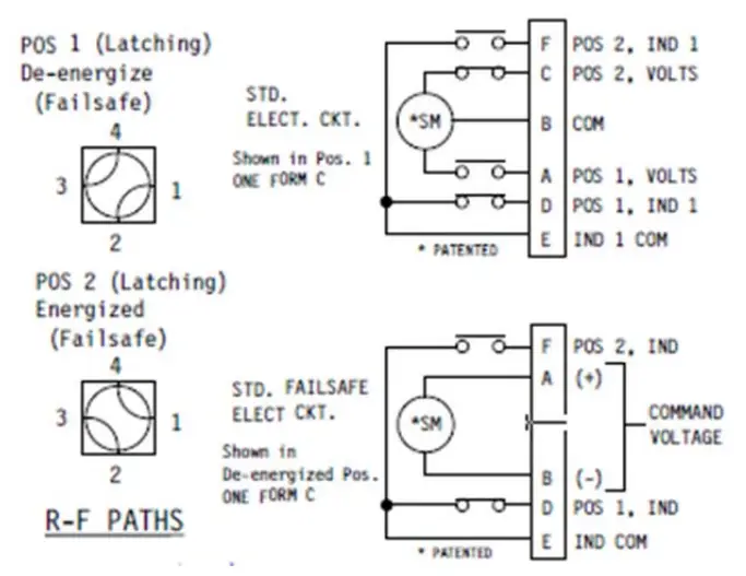
| Manual** |
| Code | Flange |
| P | Plain |
| C | Choke |
| O | O-Ring |
| F | CPRF |
| G | CPRG |
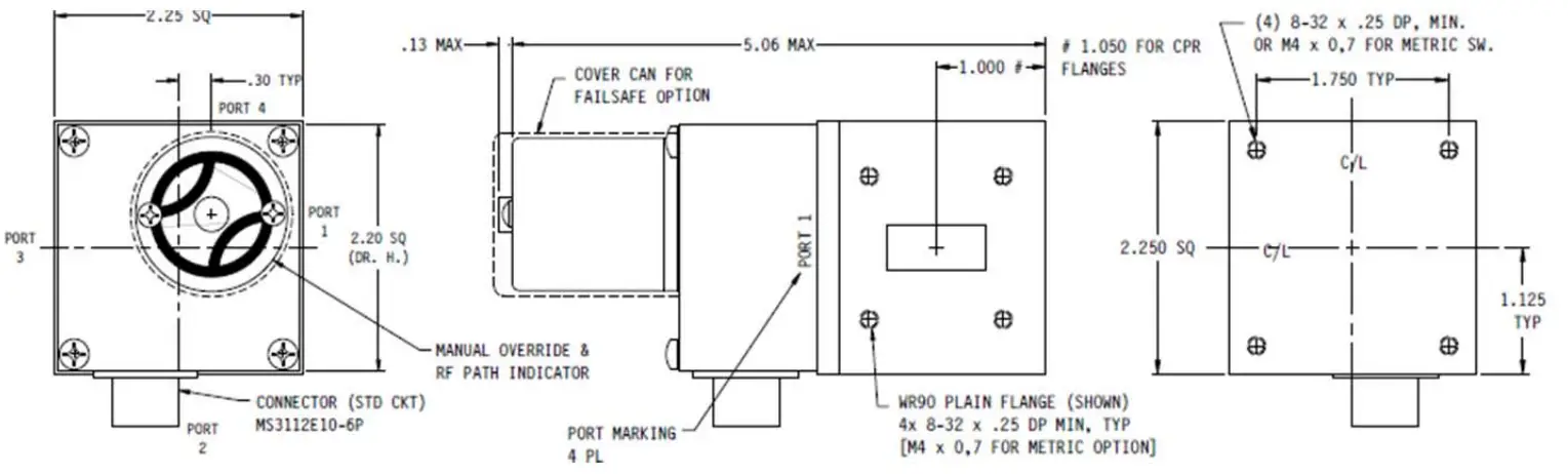
Units: Inches
Tolerances: Decimals:
2 PLACES: ± .03
3 PLACES: ± .010
FRACTIONS: ±1/32
ANGLES: ± 1/2 deg..
Order Examples: RWS-SPDT-8.2-12.4-WR90-P-12V-u18
Description: (Waveguide Switch, Single Pole Double Throw, 8.2-12.4GHz, WR90, Flat Plain Flange, 12Volts)
Specifications
| Frequency | 8.2-12.4 GHz |
| VSWR | 1.05:1 max |
| Insertion Loss | 0.05 dB max |
| Isolation | 60dB minimum |
| Switching time | 50 milli-sec typical |
| Pressure | To 30 PSIG |
| Waveguide size | WR 90 |
| Flanges (Optional see table above) | Plain Flat flange |
| Operating voltage (Optional see table above) | 12 VDC-1.5Am |
| Mating connector | To be supplied |
Note: ** manual switch does not included Receptacle
![]()
RWS-SPDT-8.2-12.4-WR90-Opt-xV-u18
Specifications may be subject to change
WORLD HQ: 1702L Meridian Ave. Suite 127, San Jose, Ca 95125, U.S.A.
Tel: (408) 266-7404
FAX: (408) 266-4483
WEB: www.raditek.com
E-mail: [email protected]


