![]() SR600
SR600
Quick Guide
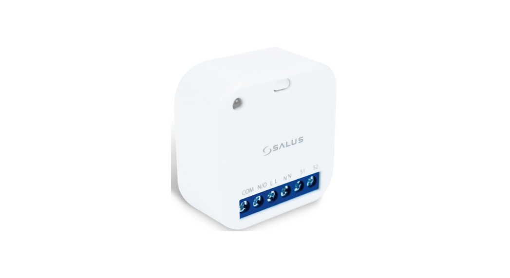
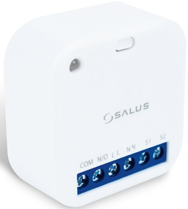
SR600 Smart Switching Relay
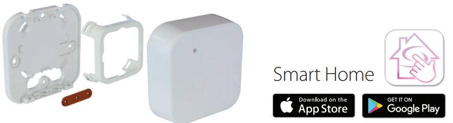
Introduction: Smart Relay (SR600) is a switching relay product that can be used to power on or off a maximum 16A load. It can be installed directly within a wall box or surface mounted onto the wall (using the optional SRS600 wall mount bracket). This product must be used with the Universal Gateway (purchased separately). The Universal Gateway allows communication with other SALUS Smart Home products using the SALUS Smart Home App.
Product Compliance: This product complies with the essential requirements and other relevant provisions of Directives 2014/53/EU (RED) and 2011/65/EU. The full text of the EU Declaration of Conformity is available at the following internet address: www.saluslegal.com.![]() 2405-2480MHz; <14dBm
2405-2480MHz; <14dBm
![]() Safety Information: Use in accordance with the regulations. Indoor use only. Keep your device completely dry. Disconnect your device before cleaning it with a dry cloth. This accessory must be fitted by a competent person, and installation must comply with the guidance, standards and regulations applicable to the city, country or state where the product is installed. Failure to comply with the relevant standards could lead to prosecution.
Safety Information: Use in accordance with the regulations. Indoor use only. Keep your device completely dry. Disconnect your device before cleaning it with a dry cloth. This accessory must be fitted by a competent person, and installation must comply with the guidance, standards and regulations applicable to the city, country or state where the product is installed. Failure to comply with the relevant standards could lead to prosecution.
Wiring diagram
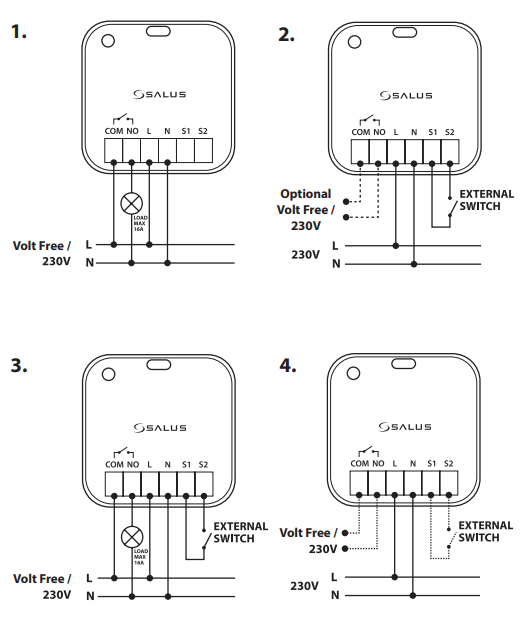
Terminals
| COM | Common terminal |
| NO | Switch terminal |
| L | Power supply 230V AC |
| N | Power supply 230V AC |
| S1/S2 | Switch input terminals |
Pairing Process
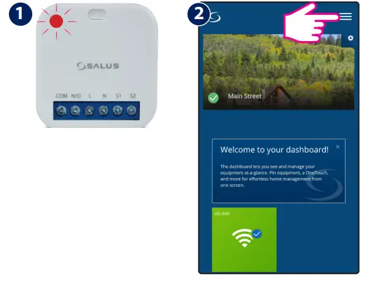
Once powered, the LED will flash red to indicate pairing mode.
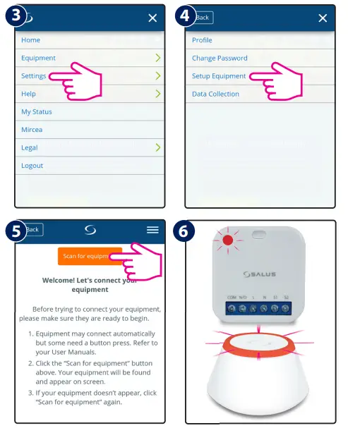
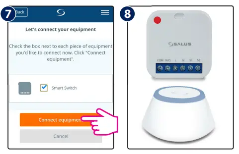
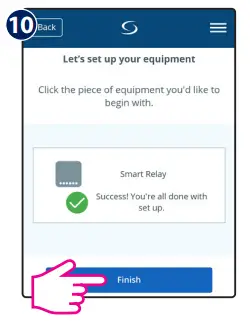
9 Follow the onscreen instructions to complete the setup.
LED Indication
| Description | LED |
| Joining Network automatically | RED LED pulsing |
| Joining Network trigger by button press | RED+GREEN LED turn on for 1s, then RED LED pulsing |
| Device Relay ON with Network | GREEN LED ON |
| Device Relay OFF with Network | RED LED ON |
| Device Relay OFF without Network | RED LED pulsing |
| Device Relay ON without Network | RED + GREEN LED pulsing |
| Identify | GREEN LED flashing for up to 10 minutes |
S1&S2 terminals
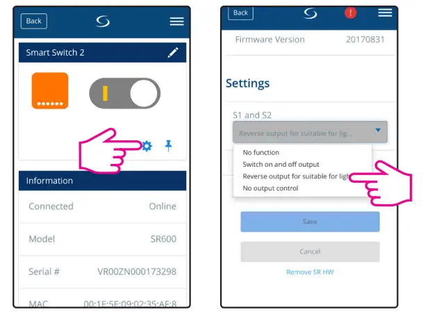
| Option | Description |
| 1. No Function | S1/S2 non-active (Turning COM/NO on using the App) |
| 2. Switch on and off output | Switch COM/NO is on, while S1/S2 contact is triggered |
| 3.Reverseoutputfor suitableforlighting | Short circuits of terminals S1/S2 ca use switching on or off (bi-stable contact) |
| 4.Nooutputcontrol | S1/S2 active and work independently of COM/NO output. Switch COM/NO is turned on via the App |
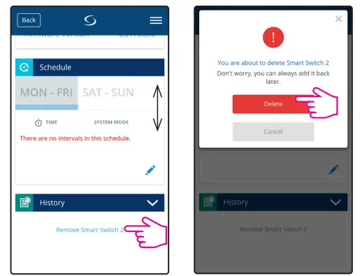
Remove device
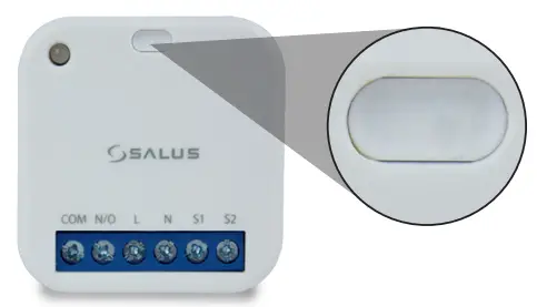
To identify the device, short press the button.
To enter pair mode, press and hold the button for 3 seconds.
To do a factory reset, press and hold the button until LED flashes red (max 15 sec).
FR/ NL / DE:
[email protected]
tel: +49 6108 8258515
www.salus-controls.com![]()
SALUS Controls is a member of the Computime Group
Maintaining a policy of continuous product development SALUS Controls plc reserve the right to change specification, design and materials of products listed in this brochure without prior notice.
Issue Date: September 2017 V002
For PDF Installation guide please go to
www.salus-manuals.com
Head Office:
SALUS Controls plc
SALUS House
Dodworth Business Park South,
Whinby Road, Dodworth,
Barnsley S75 3SP, UK.
T: +44 (0) 1226 323961
E: [email protected]