![]() 09-06-2022 Issue 2
09-06-2022 Issue 2
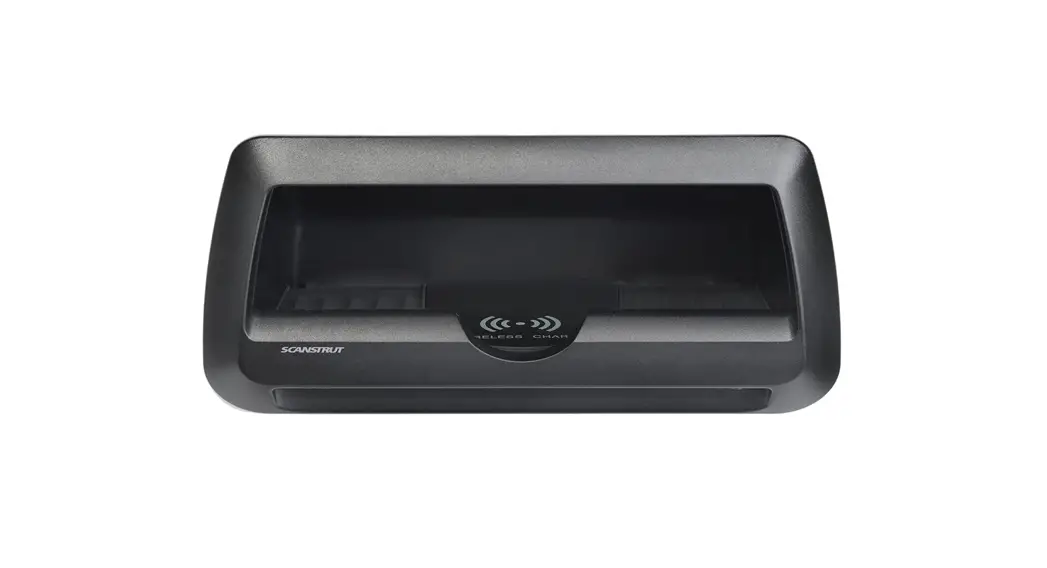
Cove. 10W (SC-CW-9F)
Cove with LED. 10W (SC-CW-10F)
Installation Instructions
Technical Information
Max phone size: 176mm (6.92”) x 92mm (3.62”) (Including case)
| Wireless Charger. SC-CW-09F and SC-CW-10F | |
| Input voltage range | 10-30V DC (12/24V system) |
| Input current max | 2A |
| Output power | 10W (9.1V, 1A) |
| Standby power draw | < 0.2W |
| Waterproof rating SC-CW-09F SC-CW-10F | IPX6 IPX5 |
| Certification | Qi, CE, FCC, ROHS, C-Tick, UNECE R10 E24, UKCA, IC, PSE |
| LED. SC-CW-10F Only | ||
| Input voltage 12V DC | 9-15V | |
| Input current max | 0.2A | |
| Standby power draw | 0.0W | |
| Optional Driver Specification | TYPE | RGB |
| Input | 12 or 24V | |
| Output | 12V | |
| Power | As required for LED harness | |
Parts List
| x1 Pocket SC-CW-09F SC-CW-10F with LED | |
| x4 No6 x 3/4” (19mm) self-tapping CSK Philips screw | 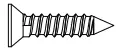 |
| x1 3 x 10mm Pan head Philips Thread forming screw | 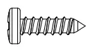 |
| x1 Front bezel | 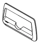 |
| x1 SC-CW-01F Wireless Charger | 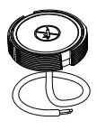 |
Tools Required
| Philips No. 2 screwdriver | |
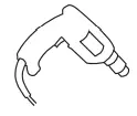 | Power drill |
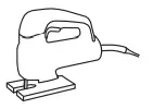 | Jigsaw |
| Drill bits 2.5mm (3/32”) 3mm (1/8”) | |
| Silicone Sealant | |
| Drill bits 5mm (3/16”) Optional |
Extras Not Supplied
| LED Driver Optional | 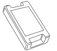 |
| Drain Pipe 8mm (5/16”) internal diameter Optional |  |
 READ THE IMPORTANT INFORMATION LEAFLET BEFORE INSTALLING
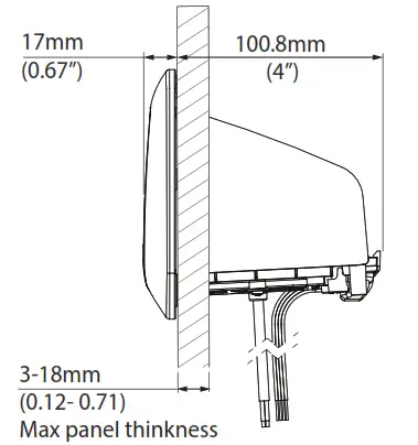
- Choose a mounting location, ensuring there is adequate space behind the mounting surface.

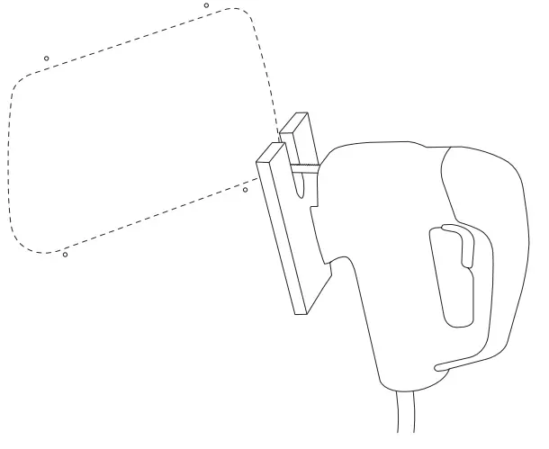
- Cut the mounting hole and drill pilot holes using the paper template.

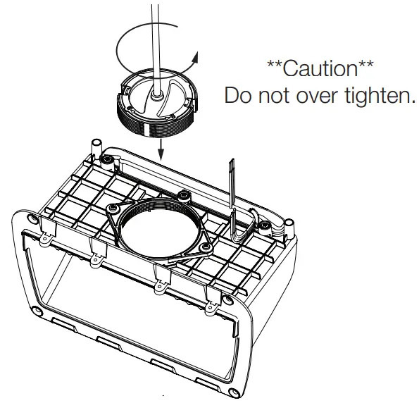
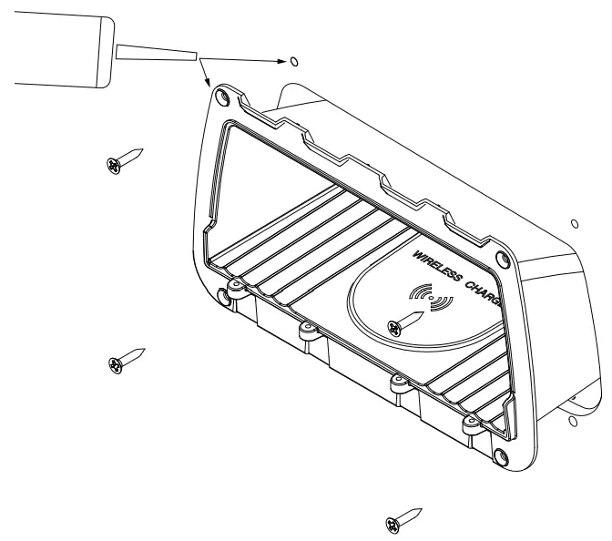
- Screw wireless charger into place.

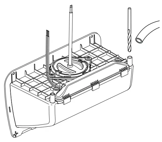
- Optional Drain Pipe:
Carefully drill drain holes using a 5mm (3/16”) drill bit. Attach drain pipe 8mm (5/16”) ID pipe, not included.
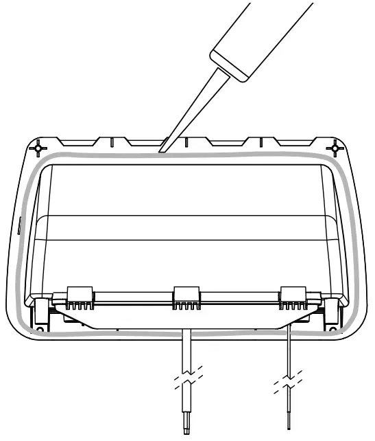
- Apply silicone sealant generously around the flange, ensuring good coverage around the perimeter.

- Add silicone sealant to screw holes and secure with x4 No6. (3.5mm) x 3/4” (19mm) self-tapping CSK Philips screws provided.

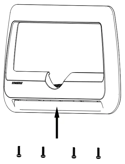
- Attach front bezel using 4, 3mm x 10mm pan head Philips thread forming screws.
 7. 1. Lower and rotate bezel into place.
2. Push the top of the bezel untill clicks.
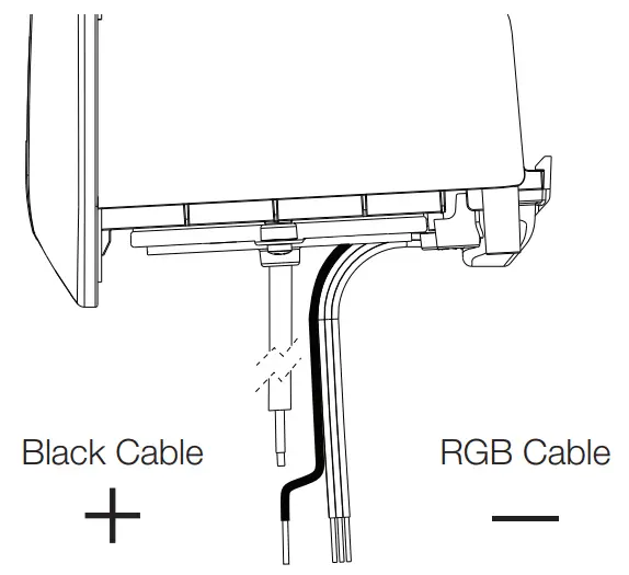
- SC-CW-10F Only:
For a single light color, make a (+) positive (black cable) and (-) negative connection (Red Green, or Blue). Or connect all three RGB cables to an RGB Controller wire harness for multicolor lighting control
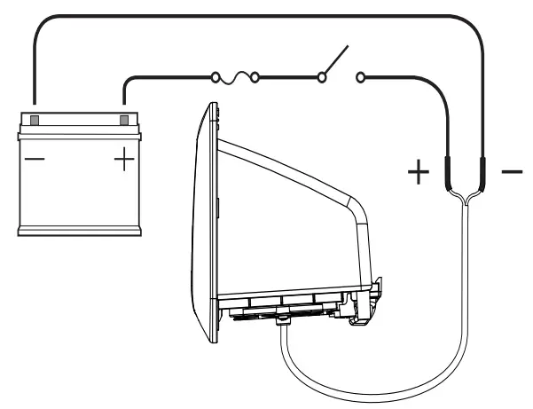
- Connect wireless charger wires to 12/24V supply, ensuring a waterproof connection. Fuse according to the input voltage and current.

 7. 1. Lower and rotate bezel into place.
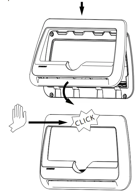
The product must be installed in accordance with the instructions provided. Failure to do so could result in personal injury, damage to your vessel/vehicle, and/or product failure. Scanstrut recommends installation is carried out by a qualified electrician. No liability is accepted for damage and/or injury caused by incorrect installation.
WARNING
This product is to be fitted to a 12V DC or 24V DC battery/power source only.
The power supply must be switched off before installation.
An appropriate fuse or circuit breaker must be used in-line between the battery/power source and the product.
Check for the correct polarity of all wiring before switching the power on.
This product may contain high voltages. Do not tamper with the product.
This product is NOT approved for use in hazardous/flammable atmospheres. Do NOT install in a hazardous/flammable atmosphere e.g. engine rooms.
Before drilling any holes, ensure the area behind the mounting location is clear of wires, fuel, and all other hazardous objects.
Ensure any holes cut will not significantly weaken the structure of the surface.
If the product needs to be mounted outside, it must be mounted in a location safely above the waterline, where it is not at risk of being submerged.
The product cannot charge through a metallic surface.
CAUTION
The product is specifically for the charging of Qi-compatible devices.
The cable must be retained and not interfere with mechanical systems.
This product contains no user-serviceable components. Do NOT attempt
to repair or alter the product in any way.
The high friction top surface does not ensure the device will not slip during extreme operating environments such as high acceleration and deceleration.
If a phone case that is thicker than 3mm is used the device may not charge.
When used in a high ambient temperature/direct sunlight the product may temporarily shut down, this is a safety feature of the electronics.
The IP rating is only valid if correctly installed using the instructions and on a perfectly flat non-porous smooth surface.
When selecting a mounting location, avoid places exposed to heat-radiating appliances and poorly-ventilated areas.
EMC INSTALLATION GUIDELINES
Scanstrut products conform to Electromagnetic Compatibility (EMC) regulations, to ensure that electromagnetic interference between equipment is minimized.
WIRING
When extending the cable from your battery/power source to the product, ensure there is a minimum of 10V being provided to the product continuously. We recommend a wire gauge of 18AWG (0.82mm2) for any length of cable extension.
This schematic is to illustrate how the product should be connected to a 12V DC or 24V DC battery/power supply.
ENVIRONMENTAL PROTECTION
Waste electrical products should not be disposed of with household waste. Please recycle where facilities exist. Check with your Local Authority or retailer for recycling advice.
IMPORTANT:
Scanstrut Ltd. accepts no responsibility for any injuries or other damages arising from the use of their products in any circumstances.
WARRANTY:
A 2-year, non-transferrable warranty covers this Scanstrut product only and not any devices that are mounted in it or on it. No warranty is given for users’ devices and users expose their devices to hazards, known or unknown, at their own risk. a
![]() FCC Warning
FCC Warning
This device complies with part 15 of the FCC Rules. Operation is subject to the following two conditions:(1) This device may not cause harmful interference, and (2) this device must accept any interference received, including interference that may cause undesired operation. Any Changes or modifications not expressly approved by the party responsible for compliance could void the user’s authority to operate the equipment. This equipment has been tested and found to comply with the limits for a Class B digital device, pursuant to part 15 of the FCC Rules. These limits are designed to provide reasonable protection against harmful interference in a residential installation. This equipment generates uses and can radiate radio frequency energy and, if not installed and used in accordance with the instructions, may cause harmful interference to radio communications. However, there is no guarantee that interference will not occur in a particular installation. If this equipment does cause harmful interference to radio or television reception, which can be determined by turning the equipment off and on, the user is encouraged to try to correct the interference by one or more of the following measures:
- Reorient or relocate the receiving antenna.
- Increase the separation between the equipment and receiver.
- Connect the equipment into an outlet on a circuit different from that to which the receiver is connected.
- Consult the dealer or an experienced radio/TV technician for help.
FCC RF exposure statement:
The equipment complies with FCC radiation exposure limits set forth for an uncontrolled environment. This equipment should be installed and operated with a minimum distance between 20cm between the radiator and your body.
FCC ID: 2APUP-SC-CW-01F

Scanstrut Ltd declares the product ‘ROKK Wireless Cove. 10W and ROKK Wireless Cove LED 10W’ SKU: SC-CW-09F and SC-CW-10F are in compliance with EMC CE-RED Directive (2014/53/EU) & standard EN 62368.
The CE certificate of conformity can be found at www.scanstrut.com/uk/compliance.
![]()


