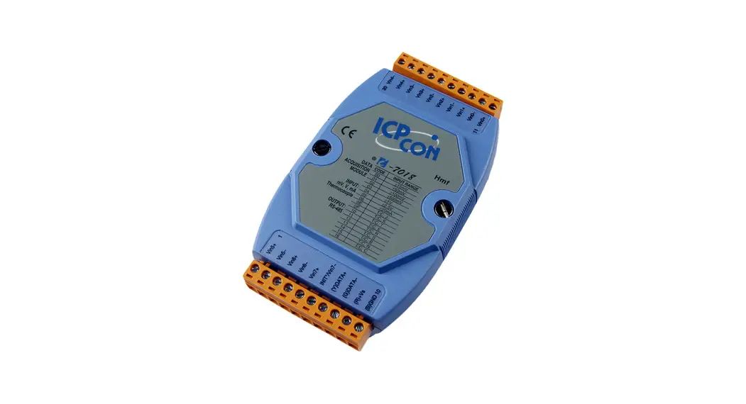
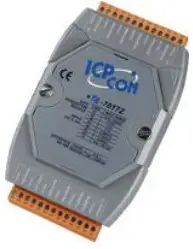
I-7018(R)(BL)(P), M-7018(R) Quick Start Guide
Warranty
All products manufactured by ICP DAS are under warranty regarding defective materials for a period of one year from the date of delivery to the original purchaser.
Warning
ICP DAS assumes no liability for damages resulting from the use of this product. ICP DAS reserves the right to change this manual at any time without notification. The information furnished by ICP DAS is believed to be accurate and reliable. However, no responsibility is assumed by ICP DAS for its use, or for any infringements of patents or other rights of third parties resulting from its use.
Packing List
| I-7018(R)(BL)(P) or M-7018(R) | Plastic Rail | CD | Quick Start Guide |
 |  |  |  |
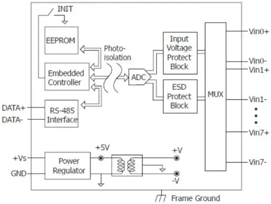
Internal I/O Structure < I-7018(BL)(P), M-7018 >
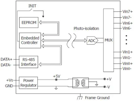
Internal I/O Structure < I-7018R, M-7018R >
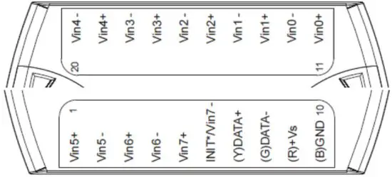
Pin Assignments < I-7018(BL)(P) >
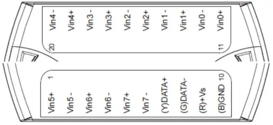
Pin Assignments < I-7018R, M-7018, M-7018R >
Wire Connections < I-7018(BL)(P) Channel 0 – 5, M-7018 , I-7018R, M-7018R >
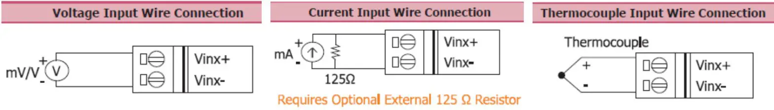
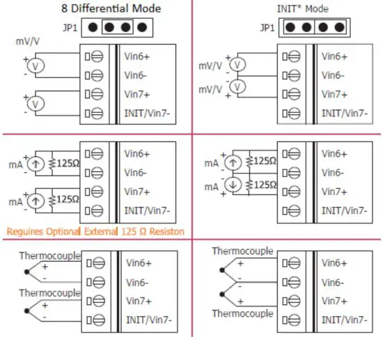
Wire Connections < I-7018(BL)(P) Channel 6 – 7 >
Modbus Table (M-7018, M-7018R only)
| Address | Description | R/W | ||||||||||||||||||||
| 30001 ~ 30008 40001 ~ 40008 | Analog input value of channel 0 to 7 | R | ||||||||||||||||||||
| 30129 40129 | CJC temperature in 0.01°C | R | ||||||||||||||||||||
| 40353 ~ 40360 | CJC offset of channel 0 to 7 in 0.1°C. 1 for 0.1, 127 for 12.7, 255 for –0.1, 128 for –12.8 | R/W | ||||||||||||||||||||
| 40481 | Firmware version (low word) | R | ||||||||||||||||||||
| 40482 | Firmware version (high word) | R | ||||||||||||||||||||
| 40483 | Module name (low word) | R | ||||||||||||||||||||
| 40484 | Module name (high word) | R | ||||||||||||||||||||
| 40485 | Module address, valid range: 1 ~ 247 | R/W | ||||||||||||||||||||
| 40486 | Bits 5:0 Baud rate, 0x03 ~ 0x0A
Bits 7:6 | R/W | ||||||||||||||||||||
| 40487 | Type code | R/W | ||||||||||||||||||||
| 40488 | Modbus response delay time in ms, valid range: 0 ~ 30 | R/W | ||||||||||||||||||||
| 40489 | Host watchdog timeout value, 0 ~ 255, in 0.1s | R/W | ||||||||||||||||||||
| 40490 | Channel enable/disable, 00h ~ FFh | R/W | ||||||||||||||||||||
| 40491 | Module CJC offset in 0.01°C | R/W | ||||||||||||||||||||
| 40492 | Host watchdog timeout count, write 0 to clear | R/W | ||||||||||||||||||||
| 00257 | Protocol, 0: DCON, 1: Modbus RTU | R/W | ||||||||||||||||||||
| 00259 | Filter setting, 0: 60Hz rejection, 1: 50Hz rejection | R/W | ||||||||||||||||||||
| 00260 | Modbus host watchdog mode 0: same as I-7000 1: can use AO and DO commands to clear host watchdog timeout status | |||||||||||||||||||||
| 00261 | 1: enable, 0: disable host watchdog | R/W | ||||||||||||||||||||
| 00268 | 1: enable, 0: disable CJC | R/W | ||||||||||||||||||||
| 00269 | Modbus data format, 0: hex, 1: engineering | R/W | ||||||||||||||||||||
| 00270 | Host watchdog timeout status, write 1 to clear the host watchdog timeout status | R/W | ||||||||||||||||||||
| 00273 | Reset status, 1: first read after powered on, 0: not the first read after powered on | R |
DCON Protocol
| Functions | Command | Response | Notes |
| Read module name | $AAM | !AA(Data) | AA: address number |
| Read module firmware version | $AAF | !AA(Data) | |
| Read all analog input data | #aa | >(data) | |
| Read analog input data of each channel (<=16 channel) | #aai | >(data) | i: channel number (Hex) |
| Read analog input data of each channel (>16 channels) | #aaii | >(data) | ii: channel number (Hex) |
If you want to know the detail DCON protocol, please check it from CD or web CD path:\\napdos\7000\manual\
Web: ftp://ftp.icpdas.com/pub/cd/8000cd/napdos/7000/manual/
Module test and configuration
Step 1: INIT switch Operation
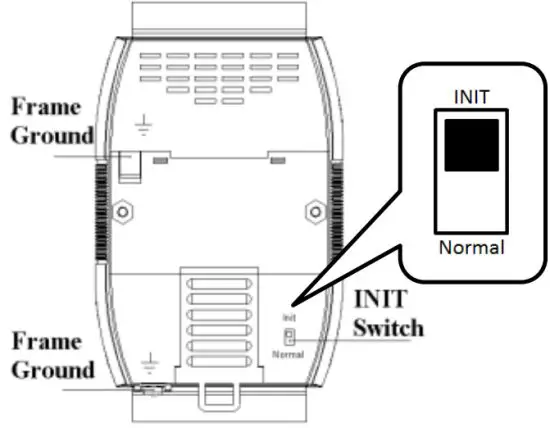
- Find out the INIT switch( back of the module), and turn to INIT.
- Reboot the module
Step 2: Install & Run DCON Utility
- Please Install DCON Utility first
You can find the software on the CD.
CD-path: <Driver>:\napdos\driver\dcon_utility\
Weblink: http://ftp.icpdas.com/pub/cd/8000cd/napdos/driver/dcon_utility/ - Run DCON utility

Step 3: Set search configuration & search module
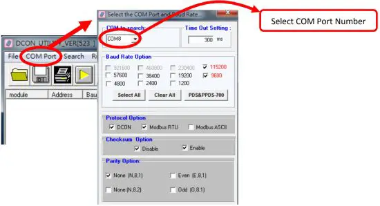
- Click “COM Port”
- Assign the communication information and click “OK”
Module Default Setting COM Port Refer converter Port Number Baud Rate 9600 Protocol DCON for I-7000
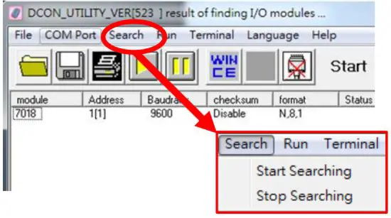
Modbus RTU for M-7000Parity Option N,8,1 - Click “Search” and select “Start Searching”
The software will search the modules from COM Port - Click “Search“ and select “stop searching”
Manual stop when the modules searched
Note:
When no module can be searched, please check the wire and communication information
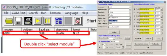
Step 4: Select Module for testing and configuration
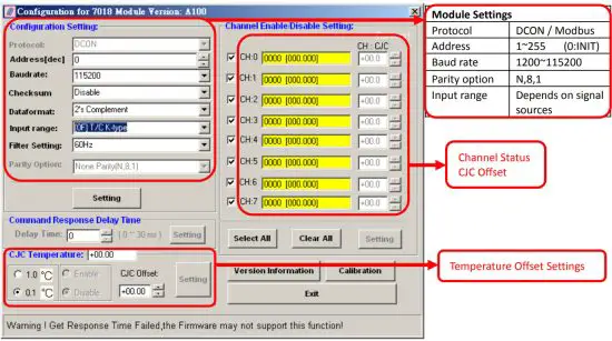
Step 5: Configuration Settings & Channel Settings
Step 6: Change to normal mode and keep the settings
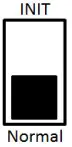
- Turn the INIT Switch to Normal.
- Reboot the module
Trouble Shooting
Q1. How to do when forgot module address or baud rate?
Please turn to INIT mode, and run DCON Utility to search.
The module supports DCON protocol at the INIT mode.
And the address is 0. The communication setting is “9600,N,8,1”.
Q2. How to configure the I-7000 and M-7000 modules?
ICP DAS provide DCON Utility to configure I-7000 and M-7000 modules.
Please download the last version from: http://ftp.icpdas.com/pub/cd/8000cd/napdos/driver/dcon_utility/
Q3. How to measure the current?
I-7018(R)(BL)(P) and M-7018(R) require optional external resistance (125Ω) for current measurement.
Please refer wired connections diagram.
And then select a suitable input range by DCON Utility.
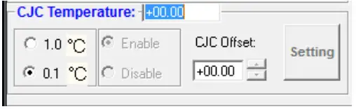
Q4. What is the CJC function?
CJC (Cold-Junction Compensation) offset is for the temperature measurement.
You can set a CJC offset for all channels or different channel in DCON Utility,
Q5. How to programming with I-7000 or M-7000 by C#, VB, VC?
ICP DAS I-7000 and M-7000 series both support DCON protocol. And Only M-7000 series supports Modbus protocol.
For DCON protocol, please download SDK and Demo from: http://ftp.icpdas.com/pub/cd/8000cd/napdos/driver/dcon_dll_new/
For Modbus protocol, please refer this web link: http://www.icpdas.com/products/PAC/i-8000/modbus.htm
If there is any other question, please feel free to contact us. Email: [email protected]
Website: http://www.icpdas.com.tw/contact_us/contact_us.htm


