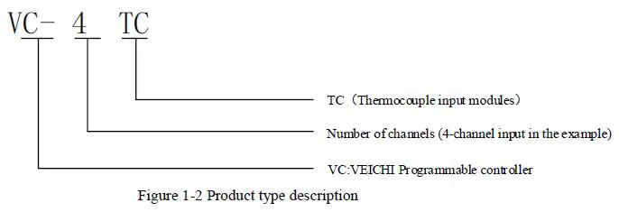
VEICHI VC-4TC Thermocouple Type Temperature Input Module

Thank you for purchasing the VC-4TC thermocouple type temperature input module developed and manufactured by Suzhou VEICHI Electric Technology Co., Ltd Before using our VC series PLC products, please read this manual carefully in order to have a clearer understanding of the product features and to install and use it correctly. You can make full use of the rich functions of this product for a safer application.
Tip:
Please read the operating instructions, precautions and cautions carefully before starting to use the product in order to reduce the risk of accidents. Personnel responsible for the installation and operation of the product must be strictly trained to comply with the safety codes of the relevant industry, strictly observe the relevant equipment precautions and special safety instructions provided in this manual, and carry out all operations of the equipment in accordance with the correct operating methods.
Interface description
Interface description
The expansion interface and user terminals of the VC-4TC are covered with flaps, the appearance of which is shown in Figure 1-1. Opening each cover reveals the expansion interface and user terminals, as shown in Figure 1-2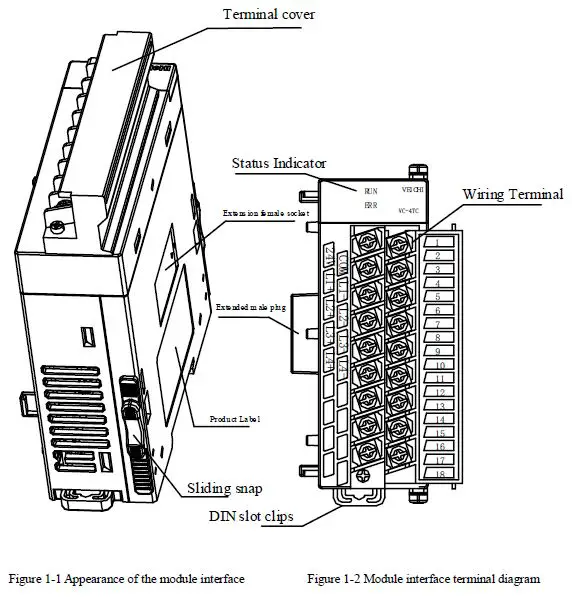
Product information
Definition of terminal
| No. | Marking | Description | No. | Marking | Description |
| 1 | 24V | Analogue power supply 24Vpositive | 2 | COM | Analogue power supply 24V negative |
| 3 | L1+ | Channel 1 thermocouple positive | 4 | L1- | Channel 1 thermocouple negative |
| 5 | L2+ | Channel 2 thermocouple positive | 6 | L2– | Channel 2 thermocouple negative |
| 7 | L3+ | Channel 3 thermocouple positive | 8 | L3- | Channel 3 thermocouple negative |
| 9 | L4+ | Channel 4 thermocouple positive | 10 | L4– | Channel 4 thermocouple negative |
| 11~18 | Reserved | ||||
Access system
The VC-4TC is used in VC series programmable controller systems and can be plugged into the system by hardwiring it, see Figure 1-3 for the access method and plugging it into the expansion interface of the main module or any expansion module in the system. Once the VC-4TC is connected to the system, its expansion interface can also be used to connect other expansion modules of the VC series, such as IO expansion modules, VC-4DA, VC-4PT, etc., and of course the VC-4TC.
The main module of the VC series programmable controller can be extended with several IO expansion modules and special function modules. The number of expansion modules to be connected depends on the amount of power the modules can provide, as described in the 4.7 Power Supply Specifications in the VC Series Programmable Controller User Manual.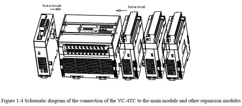
Wiring instruction
User terminal wiring requirements
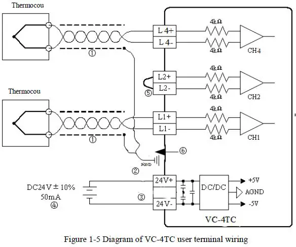
For user terminal wiring requirements, please refer to Figure 1-5. when wiring, you are requested to pay attention to the following 7 aspects. Diagrams 1 to 6 indicate the six aspects that must be taken into account when wiring.
- The thermocouple signal is recommended to be connected via a shielded compensation cable. The cable should be routed away from power lines or other wires that may cause electrical interference. The use of long compensation cables is susceptible to noise interference and it is recommended that compensation cables less than 100 meters in length are used. The presence of impedance in the compensation cable introduces measurement errors, which can be resolved by characteristic adjustment, as described in section 3 of this manual under Characteristic settings.
- If there is excessive electrical interference, connect the shield ground to the earth.
- Ground the ground terminal PE of the switching power supply well.
- The analogue power supply can use the auxiliary output 24Vdc power supply of the main module or another power supply that meets the requirements.
- Short the connection between the positive and negative terminals of the channel not in use, in case incorrect data will be detected on this channel.
- If all multiplexed thermocouples need to be connected to the shield, the terminals can be externally expanded.
Instructions for use
Power indicator
| Project | Indicator |
| Analog circuits | 24Vdc (-10% to +10%) max. allowable ripple voltage 5% 55mA (from mains module or external power supply) |
| Digital Circuit | 5Vdc, 70mA (from the main module) |
Performance indicator
| Project | Indicator | |||
| Celsius (°C) | Fahrenheit (°F) | |||
| Number of I/O points occupied | No | |||
| Input signal | Thermocouples: types K, J, E, N, T, R, S (all 7 types available for each channel), 4 channels in total. | |||
| Conversion speed | (240±2%) ms × 4 channels (no conversion for channels not in use) | |||
|
Rated temperature range | Type K | -100℃~1200℃ | Type K | -148°F ~2192°F |
| Type J | -100℃~1000℃ | Type J | -148°F ~1832°F | |
| Type E | -100℃~1000℃ | Type E | -148°F ~1832°F | |
| Type N | -100℃~1200℃ | Type N | -148°F ~2192°F | |
| Type T | -200℃~400℃ | Type T | -328°F ~752°F | |
| Type R | 0℃~1600℃ | Type R | 32°F ~2912°F | |
| Type S | 0℃~1600℃ | Type S | 32°F ~2912°F | |
|
Digital output | 16-bit AD conversion, stored as 16-bit binary complement | |||
| Type K | -1000~12000 | Type K | -1480~21920 | |
| Type J | -1000~10000 | Type J | -1480~18320 | |
| Type E | -1000~10000 | Type E | -1480~18320 | |
| Type N | -1000~12000 | Type N | -1480~21920 | |
| Type T | -2000~4000 | Type T | -3280~7520 | |
| Type R | 0~16000 | Type R | 320~29120 | |
| Type S | 0~16000 | Type S | 320~29120 | |
|
Minimum resolution | Type K | 0.8℃ | Type K | 1.44°F |
| Type J | 0.7℃ | Type J | 1.26°F | |
| Type E | 0.5℃ | Type E | 0.9°F | |
| Type N | 1℃ | Type N | 1.8°F | |
| Minimum resolution | Type T | 0.2℃ | Type T | 0.36°F |
| Type R | 1℃ | Type R | 1.8°F | |
| Type S | 1℃ | Type S | 1.8°F | |
| Total accuracy correction point | ± (0.5% full range + 1°C), pure water condensation point: 0°C/32°F | |||
| Isolation | Isolation between analogue and digital circuits with optocouplers. Isolation between the analogue circuit power supply and the 24 Vdc supply by DC/DC. | |||
| Note: With the appropriate mode setting, both °C and °F data can be obtained. | ||||
Indicator light description
| Projects | Description |
| Signal indicator | RUN status indicator, blinking when normal ERR error status indicator, illuminated on failure |
| Expansion module rear stage interface | Connection of rear modules, hot-swappable not supported |
| Expansion module front interface | Connection of front-end modules, hot-swappable not supported |
Characteristic settings
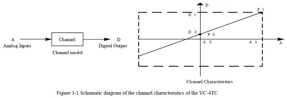
- The input channel characteristics of the VC-4TC are the linear relationship between the channel analog input temperature A and the channel digital quantity D, which can be set by the user. Each channel can be understood as the model shown in Figure 3-1, and since it is linear, the characteristics of the channel can be determined by determining two points P0 (A0, D0) and P1 (A1,D1), where D0 indicates the channel output digital quantity when the analog input is A0, and D1 indicates the channel output digital quantity when the analog input is A1.

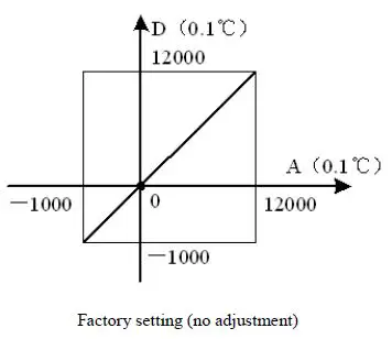
- The measurement error is caused by the impedance of the connection cable, which can be eliminated by setting the channel characteristics. Considering the user’s ease of use and without affecting the function, in the current mode, A0 and A1 are corresponding to [Measured Value 1] and [Measured Value 2] respectively, and D0 and D1 are corresponding to [Standard Value 1] and [Standard Value 2] respectively, as shown in Figure 3-1, the user can change the channel characteristics by adjusting (A0, D0) and (A1, D1), the factory default (A0, D0) is the external The factory default (A0, D0) is the 0 value of the external analogue temperature, (A1, D1) is the maximum value of the external analogue temperature 12000 (unit: 0.1℃). Factory set as shown in Figure 3-2, A0 is 0, A1 is 12000 (unit is 0.1°C).

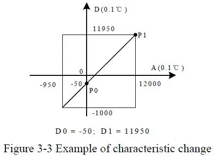
- The channel characteristics can be changed if the D0 and D1 values of the channel are changed. If the VC-4TC measurement value is 5°C (41°F) higher in practice, the error can be eliminated by setting the two points P0 (0,-50) and P1 (12000,11950) of the characteristic adjustment, see Figure 3-3 for an example.

Programming example
Programming example for VC series + VC-4TC module
As shown in the example below, the VC-4TC is connected to position 1 of the expansion module and uses channel 1 to access thermocouple type K for Celsius temperature, channel 2 to access thermocouple type J for Celsius temperature, channel 3 to access thermocouple type K for Fahrenheit temperature, channel 4 is switched off, the average number of points is set to 8 and the average conversion result is received using data registers D1, D3 and D5. The settings are shown in Figures 4-1 to 4-3. See the VC Series Programmable Controllers Programming Reference Manual for further details. Create a new project and configure the hardware for the project, as shown below.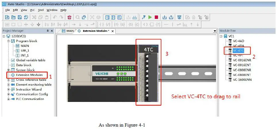
Double-click on the “4TC” module to enter the 4TC setup screen – as shown below.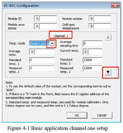
Click on “▼” for the second channel mode configuration.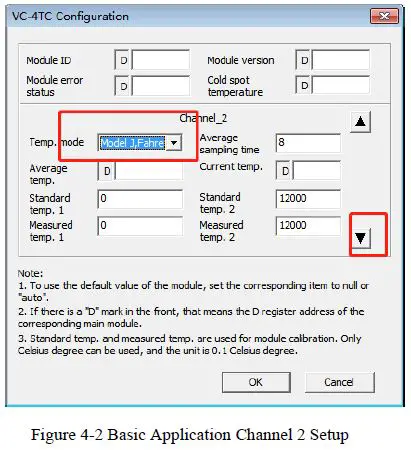
Click on “▼” to configure the third channel mode and click on “Confirm” when finished.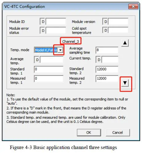
Installation
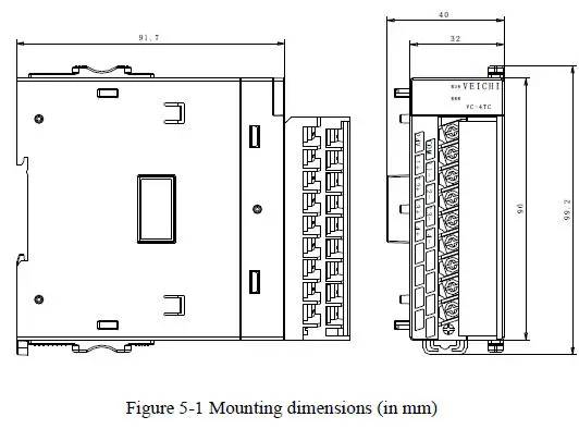
Mounting dimensions
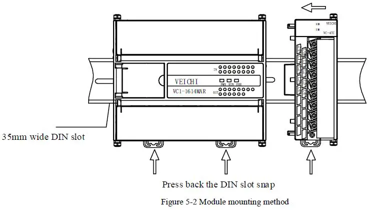
Mounting method
Operational check
Routine check
- Check that the analogue input wiring meets the requirements, refer to 1.4 Wiring instructions.
- Check that the VC-4TC is reliably plugged into the expansion connector.
- Check that the 5V and 24V power supplies are not overloaded. Note: The power supply for the digital part of the VC-4TC comes from the main module and is supplied via the expansion interface.
- Check the application to ensure that the correct operating method and parameter range has been selected for the application.
- Set the main module to which the VC-4TC is connected to RUN status.
Fault checking
If the VC-4TC is not operating properly, check the following items.
Checking the status of the main module “ERR” indicator.
- Blinking: Check the connection of the expansion module and the consistency between the configuration model of the special module and the actual connected module model.
- extinguished: the expansion interface is correctly connected.
Check the analog wiring.
- Check that the wiring is accurate, refer to Figure 1-5.
- Check the status of the module’s “ERR” indicator
If the 24V DC power supply is normal, then the VC-4TC is faulty.
- Off: 24V DC power supply is normal.
- Check the status of the “RUN” indicator
- Blinking: The VC-4TC is operating normally.
For Users
- The scope of the warranty refers to the programmable controller body.
- The warranty period is eighteen months. If the product fails or is damaged during the warranty period under normal use, we will repair it free of charge.
- The start of the warranty period is the date of manufacture of the product, the machine code is the only basis for determining the warranty period, equipment without the machine code is treated as out of warranty.
- Even within the warranty period, a repair fee will be charged for the following cases. failure of the machine due to non-operation in accordance with the user manual.
Damage to the machine caused by fire, flooding, abnormal voltage, etc.
Damage is caused when using the programmable controller for a function other than its normal function. - The service charge will be calculated on the basis of the actual cost, and if there is another contract, the contract will take precedence.
- Please make sure that you keep this card and present it to the service unit at the time of warranty.
- If you have a problem, you can contact your agent or you can contact us directly.
Suzhou VEICHI Electric Technology Co., Ltd
China Customer Service Center
- Address: No. 1000, Songjia Road, Wuzhong Economic, and Technological Development Zone
- Tel: 0512-66171988 Fax: 0512-6617-3610
- Service hotline: 400-600-0303 website: www.veichi.com.
- Data version v1 0 was filed on July 30, 2021
All rights reserved. The contents are subject to change without notice.
VEICHI Product warranty card
|
Customer information | Company address: | |
| Company name: | contacts: | |
| contact number: | ||
|
Product information | Product model: | |
| Body barcode: | ||
| Name of agent: | ||
| Fault information | Maintenance time and content: Repairer: | |
| Mailing address | Suzhou VEICHI Electric Technology Co., Ltd Address: No. 1000, Songjia Road, Wuzhong Economic and Technological Development Zone | |


