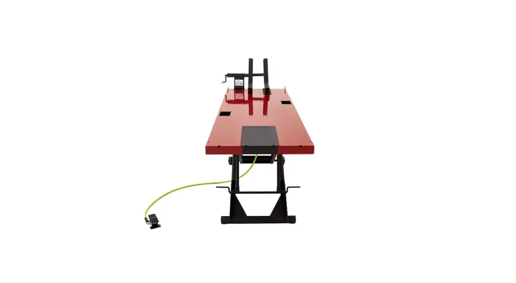
![]() BW-8630-KIT BW Series Lift Table with Cycle Vise
BW-8630-KIT BW Series Lift Table with Cycle Vise
User Guide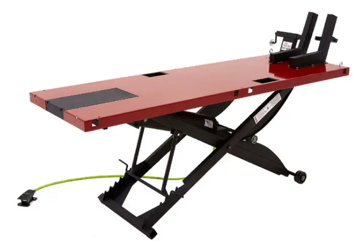
 GENERAL GUIDELINES & SAFETY
- It is the user’s responsibility to read and follow all instructions.
- Keep these instructions with the product at all times and review before each use.
- It is the responsibility of this product’s owner to furnish the instructions to any person that borrows or purchases the product.
- Inspect the product before use to ensure it is assembled properly and all parts are in safe working order and free of defects.
- Never modify this product in any way.
- All circumstances cannot be addressed in these instructions.
- Please use common sense and practice general safety measures when using this product.
- Parts and/or instructions are subject to change without notice.
- Do not exceed capacity center load of 1,200 lbs.
- Recommended air pressure is 110 PSI.
- Keep safety bar engaged with variable lock heights when in use.
- To lower, raise table off safety bar, flip bar up and secure to tension clips, release air slowly lowering table to desired height.
- Keep hands and tools from under table – avoid multiple pinch points.
- Do not load table or climb onto table when elevated.
- Use caution when placing vehicle onto lift – riding vehicle onto lift is not recommended.
- Ground surface should be flat and level.
- Tie down straps are recommended with eye bolts secured to table.
- Ensure air hose is clear from frame when lowering to avoid pinching hose.
ASSEMBLY
- Remove the packaging and check the contents.
- Assemble the eyebolts to the lift top.
- Assemble an air line connector to the air valve into the port marked with an “A”.
- Assemble the ramp to the end of the lift.
- Assemble as needed the accessories such as cycle vise or wheel chock to the lift table.
- When using side extensions; place the support bar through the 2” square tubing at the bottom of lift.
- Attach Side Extensions to the lift if applicable.
- Operate the lift without any load for the first time to check operation and speed.
OPERATION
- Always check for vertical clearance prior to operating the lift.
- Use the ramp(s) to place vehicle on the lift. Loads must be centered on the table at all times.
- Always restrain the vehicle being lifted, strap to the eyebolts.
- Use the foot valve to raise the lift, release safety bar from tension clips, and lower to engage the safety bar at desired working heights.
- Ensure that the air hose is clear from the frame when lowered into the lowest position.
| Model | Capacity | Weight | Dimensions |
| BW-8630-KIT | 1200 lbs | 445 lbs. | 30″ x 86″ |
| BW-8660-KIT | 1200 lbs | 600 lbs. | 60″ x 86″ |
| BW-9030-KIT | 1200 lbs | 460 lbs | 30″ x 90″ |
| BW-9060-KIT | 1200 lbs | 615 lbs | 60″ x 90″ |
OPERATIONAL CHECKS AND MAINTENANCE
- Check all working parts for any damage or disconnection.
- Check air hose connections for leaks.
- Add air tool oil every 3-6 months as needed through foot valve supply line.
- Grease pivot pins as needed.
- Grease bearing cams and table bearing tracks as needed. (Grease requirements vary based on use and loads applied)
PARTS
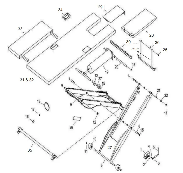
| ITEM | PART NO | DESCRIPTION | OTY |
| 19 | 2085 | Cylinder, Air | 1 |
| 20 | 2053 | Pin, Cylinder Pivot | 1 |
| 21 | 2054 | Pin, Top | 2 |
| 22 | 2506. | Spacer, Top | 2 |
| 23 | 2066. | Decent Bar Assy | 1 |
| 24 | 2066. | Decent Bar Assy | 1 |
| 25 | 2055 | Pin Decent Bar | 2 |
| 26 | 11 HP | Hairpin Clip | 2 |
| 27 | 2089 | Black Widow Decal | 1 |
| 28 | 2009B | Ramp | 1. |
| 29 | 2037B | Dropout | 1 |
| 30 | 2073 | Table Support | 1 |
| 31 | 2000B | Top,BW-8630 | 1 |
| 32 | 2035 | Top, BW.9030 | 1 |
| 33 | 2032B | Side Extension | 1-4 |
| 34 | 2038 | Parts Tray | 2 |
| 35 | 2058 | Stabilizer | 1 |
| 1 | 4F230C | Air Valve, Foot Pedal | 1 |
| 2 | 14CSPLG-GALV | Hex Socket Plug, 1/4 NPT | 1 |
| 3 | 2176 | Elbow, Street 1/4 NPT | 2 |
| 4 | 2176 | Hex Nipple, Brass 1/4 NPT | 1 |
| 5 | HEZ3806YW2B | Hose, Swivel, Whip, 6′ x 3/8″ | 1 |
| 6 | 2005 | Shaft, Pivot | 2 |
| 7 | K-14A | Zerk, Grease | 2 |
| 8 | 2106 | Frame, Inside Welded | 1 |
| 9 | 2107 | Frame, Outside Yielded | 1 |
| 10 | 2100 | Wheel, 4″ Phenolic | 2 |
| 11 | SH-75 | Snap Ring, 3/4″ external | 6 |
| 12 | 1628-2RS | Bearing, ball sealed | 2 |
| 13 | 5305-2RS | Bearing, ball sealed | 4 |
| 14 | 2508-1 | Spacer | 2 |
| 15 | SH-75 | Snap Ring, 3/4″ external | 10 |
| 16 | 2011 | Busing, Nylon | 1 |
| 17 | 2080 | Seal, U-Cup, Rod | 1 |
| 18 | 2081 | Seal, U-Cup, Piston | 1 |
PRODUCT WARRANTY & LIABILITY
GENERAL PRODUCT WARRANTY: Products purchased from the Authorized Dealer (original place of purchase) or Merchant (“Dealer”) will be free of defects in material and workmanship at the time of receipt, and will meet the specifications stated at the place of purchase transaction or online at the Dealer’s website, under normal use and service when correctly installed, operated and maintained.
This product warranty is effective for the period of time stated below, unless otherwise stated in the product instructions or depicted in the product advertisement. All Authorized Dealer warranties are NON-TRANSFERABLE and cover only the original end purchaser. This limited warranty does not cover products purchased through non-authorized dealers. Non-authorized dealer receipts are not accepted for warranty verification.
***WARRANTY CLAIMS MUST BE MADE DIRECTLY TO THE ORIGINAL PLACE OF PURCHASE.***
WARRANTY PERIOD: This warranty remains in force for one year from the date of the product’s accepted delivery. The Authorized Dealer offers a one year manufacturer’s warranty for most products unless otherwise specified on the product advertisement.
WARRANTY SERVICE: The Authorized Dealer will replace any defective or malfunctioning part at no charge, including payment of the shipping costs of parts or replacement product to and from the manufacturer. The purchaser is responsible for labor charges. If the product does not meet specifications as depicted in the advertisement, the Authorized Dealer will refund the full purchase price of the product.
Questions regarding the warranty on a specific product and warranty claims should be directed to the Authorized Dealer with whom the purchase transaction was made.
WARRANTY LIMITATIONS: The above warranty does not apply to products that are repaired, modified or altered by any party other than the Authorized Dealer; are subjected to unusual physical stress or conditions (such as overloaded ramps or corrosion), natural disaster, governmental actions, wars, strikes, labor disputes, riots, theft, vandalism, terrorism or any reason beyond reasonable control; are damaged due to improper installation, misuse, abuse, accident or negligence in use, storage, transportation or handling, or tampering; or to products that are considered consumable items or items requiring repair or replacement due to normal wear and tear.
Product should be inspected prior to signing for delivery. Product damage incurred during shipping, unless noted on the Bill of Lading at the time of delivery, renders this warranty void.
LIMITED LIABILITY: In no event shall THE AUTHORIZED DEALER be liable to the purchaser or any third party for any indirect, incidental, consequential, special, exemplary or punitive damages arising out of the use of the product, including, without limitation, property damage, loss of value of the product or any third party products that are used in or with the product, or loss of use of the product or any third party products that are used in or with the product.
![]() 1-888-651-3431
1-888-651-3431


