
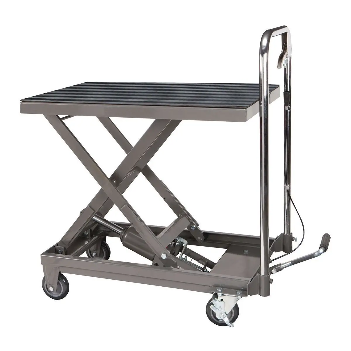
HARBOR FREIGHT 61405 Hydraulic Lift Table
Visit our website at: http://www.harborfreight.com
Email our technical support at: [email protected]
When unpacking, make sure that the product is intact and undamaged. If any parts are missing or broken, please call 1-888-866-5797 as soon as possible.
WARNING: Read this material before using this product. Failure to do so can result in serious injury. SAVE THIS MANUAL.
IMPORTANT SAFETY INFORMATION
Assembly Precautions
- Wear ANSI-approved safety goggles and heavy-duty work gloves during assembly and use.
- Keep assembly area clean and well lit.
- Assemble only according to these instructions. Improper assembly can create hazards.
- Keep bystanders out of the area during assembly.
- Do not assemble when tired or when under the influence of drugs or medication.
Use Precautions
- Do not exceed 500 lb max weight capacity. Be aware of dynamic loading! Sudden load movement may briefly create excess load causing product failure.
- Use only on flat, level and hard surface capable of supporting the Lift Table and any item(s) placed on Table. Evenly distribute load on Table to avoid tipping.
- Use as intended only. Do not use Lift Table to lift or transport people.
- Follow all hydraulic bleeding instructions specified in this manual.
- This product is not a toy. Do not allow children to play with or near this item.
- Use as intended only.
- Do not adjust Safety Valve.
- Keep clear of load while lifting and lowering.
- Lower load slowly.
- Do not use for aircraft purposes.
- Inspect before every use; do not use if parts are loose or damaged.
- Maintain product labels and nameplates. These carry important safety information. If unreadable or missing, contact Harbor Freight Tools for a replacement.
Specifications
| Capacity | 500 lb |
| Lift Range | 9-1/4″ – 28-1/2″ |
| Table Size | 27-3/4″ x 17-3/4″ |
Assembly Instructions
Read the ENTIRE IMPORTANT SAFETY INFORMATION section at the beginning of this document including all text under subheadings therein before set up or use of this product.
- With assistance, grip the Base (9) of the Hydraulic Lift Table and lift it from the box. Do not just grip the Table. Doing so will
leave the unit’s frame in the packaging. - Alternative: set the packaging sideways, grip the Base, and slide the Lift Table out of the box.


- Turn the Lift Table on its side.
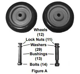
- Slide Bushing through center hole in front Wheel (12).
- Set Wheel in the Wheel frame of the Base (9).
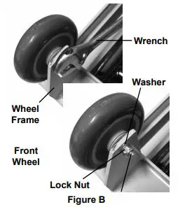
- Slide the Bolt (14) through the Washer (29), Wheel Frame, and Bushing (13).
- Use a wrench (sold separately) to fasten Lock Nut onto Bolt, until the Front Wheel is secured in place.
- Repeat steps 3-7 for other front Wheel.
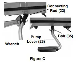
- Slide Pump Lever (23) into Connecting Rod (22), aligning the installation holes.
- Slide the Bolt (35) through the Washer (15) and through the installation holes.
- Use the wrench to fasten the Lock Nut over the Bolt, securing Pump Lever (23) in place. See Figure C.

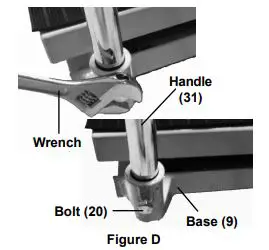
- Slide the ends of the Handle (31) into the handle slots on the Base.
- Use the wrench to tighten the Bolts (20) until the Handle is fastened in place. See Figure D.

- Test the Lift Table to make sure it functions properly before using it to lift a load.
Operating Diagram
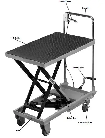
Operating Instructions
Read the ENTIRE IMPORTANT SAFETY INFORMATION section at the beginning of this manual including all text under subheadings therein before set up or use of this product.
- Lock the back Casters to prevent the Lift Table from moving.
- Raise the Lift Table by pumping the Pump Lever.
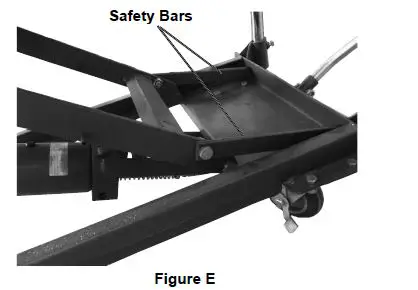
- Once the desired height is reached, engage the Safety Bars on sides of the Lift Frame by swinging them back towards the handle. Lower the table slightly and make sure the bars lock in place. See Figure E. This helps prevent uncontrolled Lift Table drop.

- To lower the Lift Table, pump the table up until the Safety Bars can be disengaged.
- Swing the Safety Bars up away from the Handle, towards their original position.
- Squeeze the Control Lever (33) to slowly lower the Lift Table.
Maintenance
Note: Procedures not specifically explained in this manual must be performed only by a qualified technician.
WARNING: TO PREVENT SERIOUS INJURY FROM TOOL FAILURE:
Do not use damaged equipment. If abnormal noise or vibration occurs, have the problem corrected before further use.
Cleaning, Maintenance, and Lubrication
- BEFORE EACH USE, inspect the general condition of the tool. Check for:
• loose hardware,
• misalignment or binding of moving parts,
• caster brake function,
• hydraulic fluid leakage (hydraulic components not user-serviceable)
• cracked or broken parts, and
• any other condition that may affect its safe operation. - AFTER USE, wipe external surfaces of the tool with clean cloth.
- If the Control Lever Does not lower the Lift Table easily, adjust the Pull Rod (32).
WARNING! Press the Control Lever only halfway down during adjustment. This will allow the Lift Table to lower slowly for safety purposes.
a. With assistance, tip over Table Cart.
b. Loosen the Bolt (35) and Nut (25) and adjust the Pull Rod until it is tight.
c. Re-fasten the Nut and Bolt. Then test the Control Lever, making sure it is pressed halfway down.
Bleeding Instructions
If the Lift Table is not performing properly, it may be due to air in the hydraulic system. Follow these steps to bleed air from the system.
- Raise the Lift Table to its highest position.
- Swing down the two Safety Bars so that they both rest on the top platform of the Base Assembly.
- Carefully remove the rubber Fluid Plug (4a).
- After the Fluid Plug is removed, swing the two Safety Bars back against their stops.
- Squeeze the Control Lever to lower the Lift Table. This should purge the air out of the hydraulic system.
- Raise the Lift Table to its highest position and swing both Safety Bars down onto the Base Assembly (17).
- Fill the Fluid Tank (5a) with new Hydraulic Fluid (not included).
- Replace the Fluid Plug by firmly pressing it into the fluid hole while twisting it.
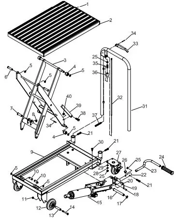
Parts Lists and Diagrams
Main Parts List
| Part | Description | Qty |
| 1 | Protective Mat | 1 |
| 2 | Lift Table | 1 |
| 3 | Scissor Arm | 1 |
| 4 | Roller | 4 |
| 5 | Retaining Ring 12 | 8 |
| 6 | Pin | 2 |
| 7 | Pin | 1 |
| 8 | Retaining Ring 14 | 2 |
| 9 | Base | 1 |
| 10 | Pin | 2 |
| 11 | Lock Nut M8 | 2 |
| 12 | Wheel 4″ | 2 |
| 13 | Bushing | 2 |
| 14 | Hex Bolt M8x60 | 2 |
| 15 | Ram | 1 |
| 16 | Pin | 1 |
| 17 | Retaining Ring 16 | 2 |
| 18 | Pin 8X40 | 1 |
| 19 | Cotter Pin 2.5X24 | 1 |
| 20 | Bushing | 2 |
| Part | Description | Qty |
| 21 | Hex Bolt M8x35 | 3 |
| 22 | Connecting Rod | 1 |
| 23 | Pump Lever | 1 |
| 24 | Foot Pedal | 1 |
| 25 | nut M8 | 10 |
| 26 | Rubber Pad | 1 |
| 27 | Locking Swivel Caster 4″ | 2 |
| 28 | Spring Washer 8 | 8 |
| 29 | Washer 8 | 8 |
| 30 | Hex Bolt M8x16 | 8 |
| 31 | Handle | 1 |
| 32 | Pull Rod | 1 |
| 33 | Control Lever | 1 |
| 34 | Roll Pin 6X26 | 3 |
| 35 | Bolt M8x25 | 1 |
| 36 | Jacket | 1 |
| 37 | Spring | 1 |
| 38 | Hex Bolt M10x30 | 2 |
| 39 | Safety Bar | 2 |
| 40 | nut M10 | 2 |
PLEASE READ THE FOLLOWING CAREFULLY
THE MANUFACTURER AND/OR DISTRIBUTOR HAS PROVIDED THE PARTS LIST AND ASSEMBLY DIAGRAM IN THIS DOCUMENT AS A REFERENCE TOOL ONLY. NEITHER THE MANUFACTURER OR DISTRIBUTOR MAKES ANY REPRESENTATION OR WARRANTY OF ANY KIND TO THE BUYER THAT HE OR SHE IS QUALIFIED TO MAKE ANY REPAIRS TO THE PRODUCT, OR THAT HE OR SHE IS QUALIFIED TO REPLACE ANY PARTS OF THE PRODUCT. IN FACT, THE MANUFACTURER AND/OR DISTRIBUTOR EXPRESSLY STATES THAT ALL REPAIRS AND PARTS REPLACEMENTS SHOULD BE UNDERTAKEN BY CERTIFIED AND LICENSED TECHNICIANS, AND NOT BY THE BUYER. THE BUYER ASSUMES ALL RISK AND LIABILITY ARISING OUT OF HIS OR HER REPAIRS TO THE ORIGINAL PRODUCT OR REPLACEMENT PARTS THERETO, OR ARISING OUT OF HIS OR HER INSTALLATION OF REPLACEMENT PARTS THERETO.
Record Serial Number Here:
Note: If product has no serial number, record month and year of purchase instead.
Note: Some parts are listed and shown for illustration purposes only, and are not available individually as replacement parts. Specify UPC 792363614054 when ordering parts.
Main Assembly Diagram
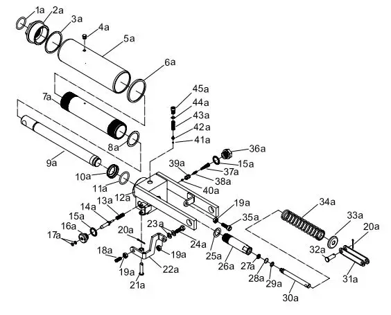
Parts List A – Ram
| Part | Description | Qty |
| 1a | O-Ring | 1 |
| 2a | Top Nut | 1 |
| 3a | Sealing Gasket | 1 |
| 4a | Fluid Plug | 1 |
| 5a | Fluid Tank | 1 |
| 6a | T-Ring | 1 |
| 7a | Cylinder | 1 |
| 8a | Copper Washer | 1 |
| 9a | Ram | 1 |
| 10a | O-Ring Retainer | 1 |
| 11a | O-Ring | 1 |
| 12a | Base | 1 |
| 13a | Spring | 1 |
| 14a | Release Valve | 1 |
| 15a | Seal Washer 20 | 2 |
| 16a | Axle Sleeve | 1 |
| 17a | O-Ring | 2 |
| 18a | Screw M8x20 | 1 |
| 19a | Nut M8 | 3 |
| 20a | Cotter Pin 2.5X24 | 2 |
| 21a | Pin | 1 |
| 22a | Release Valve Link | 1 |
| 23a | Washer 8 | 2 |
| Part | Description | Qty |
| 24a | Bolt M8x25 | 1 |
| 25a | Seal Washer | 1 |
| 26a | Pump Cylinder | 1 |
| 27a | U-Cup | 1 |
| 28a | O-Ring | 2 |
| 29a | Retainer Ring | 1 |
| 30a | Pump Piston | 1 |
| 31a | Linkage | 1 |
| 32a | Pin 8X24 | 1 |
| 33a | Spring Cap | 1 |
| 34a | Sping | 1 |
| 35a | Bolt M8x25 | 1 |
| 36a | Plug | 1 |
| 37a | Spring | 1 |
| 38a | Pumping Valve Spindle | 1 |
| 39a | Pumping Valve Seat | 1 |
| 40a | Steel Ball 6.35 | 1 |
| 41a | Steel Ball 5 | 1 |
| 42a | Ball Seat | 1 |
| 43a | Spring | 1 |
| 44a | O-Ring | 1 |
| 45a | Adjusting Bolt | 1 |
Assembly Diagram A – Ram
Limited 90 Day Warranty
Harbor Freight Tools Co. makes every effort to assure that its products meet high quality and durability standards, and warrants to the original purchaser that this product is free from defects in materials and workmanship for the period of 90 days from the date of purchase. This warranty does not apply to damage due directly or indirectly, to misuse, abuse, negligence or accidents, repairs or alterations outside our facilities, criminal activity, improper installation, normal wear and tear, or to lack of maintenance. We shall in no event be liable for death, injuries to persons or property, or for incidental, contingent, special or consequential damages arising from the use of our product. Some states do not allow the exclusion or limitation of incidental or consequential damages, so the above limitation of exclusion may not apply to you.
THIS WARRANTY IS EXPRESSLY IN LIEU OF ALL OTHER WARRANTIES, EXPRESS OR IMPLIED, INCLUDING THE WARRANTIES OF MERCHANTABILITY AND FITNESS.
To take advantage of this warranty, the product or part must be returned to us with transportation charges prepaid. Proof of purchase date and an explanation of the complaint must accompany the merchandise. If our inspection verifies the defect, we will either repair or replace the product at our election or we may elect
to refund the purchase price if we cannot readily and quickly provide you with a replacement. We will return repaired products at our expense, but if we determine there is no defect, or that the defect resulted from causes not within the scope of our warranty, then you must bear the cost of returning the product.
This warranty gives you specific legal rights and you may also have other rights which vary from state to state.


