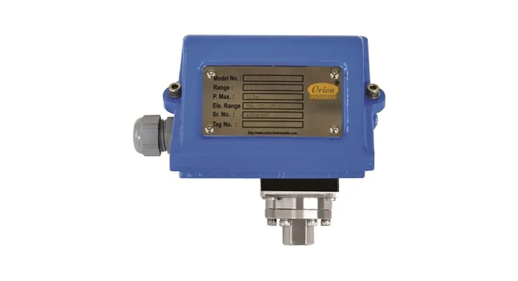
![]() MT Series Hydraulic Diaphragm Switch
MT Series Hydraulic Diaphragm Switch
Instruction Manual MD/MT
MD/MT
HYDRAULIC DIAPHRAGM SWITCH![]() MT
MT
MT Series Hydraulic Diaphragm Switch
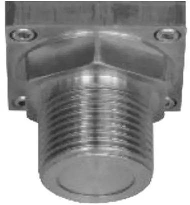
PRESSURE CAPSULE DETAILS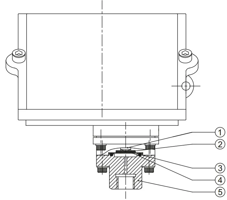
| No. | Description |
| 1 | Transfer Pin (SS) |
| 2 | Cushioning Pad |
| 3 | ‘O’ ring(PTFE ®) |
| 4 | Diaphragm (PTFE ®) |
| 5 | Pressure Housing (SS316) |
Note : wetted parts are mentioned in italics.
*Pressure ports are brazed with flange
INSTALLATION DRAWING
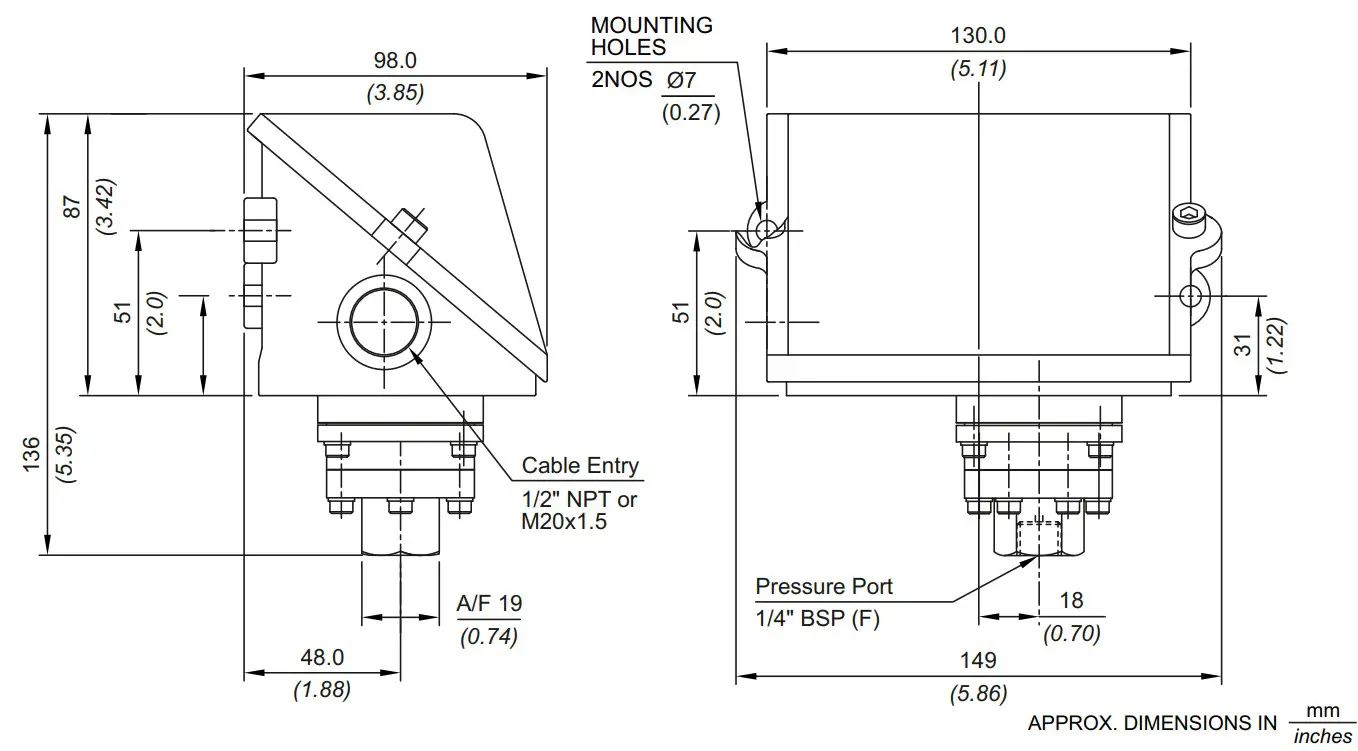 MD/MT HYDRAULIC DIAPHRAGM SWITCH
RANGE SELECTION TABLE
| Range Code | Range bar (psi) | Differential* bar (psi) Approximate Maximum for “A8” microswitch | Maximum Working Pressure bar (psi) |
| H1T | 0.5 – 10 (7.25 – 145.04) | 1 (14.50) | 150 (2175.51) |
| H2T | 2 – 20 (29.00 – 290.07) | 2 (29.00) | 200 (2900.76) |
| H4T | 5 – 40 (72.52 – 580.15) | 5 (72.52) | 200 (2900.76) |
| H1H | 10 – 100 (146.04 – 1450.38) | 12 (174.05) | 200 (2900.76) |
| H2H | 7 – 200 (101.52 – 2900.76) | 24 (348.09) | 400 (5801.52) |
| H4H | 40 – 400 (580.15 – 5801.52) | 50 (725) | 500 (7251.88) |
| H7H | 70 – 700 (1015.26 – 10152.64) | 70 (1015.26) | 800 (11603) |
| H1K | 100 – 1000 (1450.37 – 14503.77) | 100 (1450.37 ) | 1100 (15954.15) |
Note:
- The minimum differential increases with the setpoint. The differential values mentioned in the above table are approximate maximum for FSR. The differential value will vary according to the pressure range selected and microswitch type. For actual values of differential please contact sales office.
 Note: Welded diaphragm also available as shown
 - When using 2SPDT switching arrangement, both microswitches may not actuate and/or deactuate at the same point. A small stage gap, normally upto +/- 5% FSR (depending on range code) may be observed. The On-Off differential (hysterisis) typically tends to be atleast double of those published for 1SPDT pressure switches.
If actuation and/or deactuation at same point is critical part of operation, then it can be achieved by using a separate DPDT relay. This relay will need a separate power supply for it’s coil.
 Note: Welded diaphragm also available as shown
HOW TO ORDER INDUSTRIAL HYDRAULIC DIAPHRAGM RANGE PRESSURE SWITCHES
| Group 1 | Group 2 | Group 3 | Group 4 | Group 5 | Group 6 | Group 7 | Group 8 |
| Non standard allocation | Gas Group Classification | Cable Entry Size | Switch Type | Range Code (values in bar) | Microswitch Type | Pressure Port Material / Size | Diaphragm |
| Reserved for non-standard options not covered in catalogue. Will be given by manufacturer, only after agreement of supply details with customer | MD = Industrial pressure switch with IP66 rated enclosure as per IS/IEC 60529 MT = Industrial pressure switch with IP66 rated enclosure as per IS/IEC 60529 | 1 = Al. enclosure IA” NPT threads *2 = Al. enclosure %” NPT threads 3 = Al. enclosure M20 X 1.5 threads 7 = SS enclosure, %” NPT threads *8 = SS enclosure, %” NPT threads 9 = SS enclosure, M20 X 1.5 threads *Not available for MT model For dual cable entry contact Sales Office | PF1 = pressure switch, fixed differential without scale PF2 = pressure switch, fixed differential with scale in bar PF3 = pressure switch, fixed differential with scale in psi *PA1 = pressure switch, adjustable differential without scale *PA2 = pressure switch, adjustable differential with scale in bar *PA3 = pressure switch, adjustable differential with scale in psi *Available with A6, A7, A9 & B9 (in group 6) only | HIT = (0.5 – 10) H2T = (2 – 20) H4T = (5 – 40) H1H = (10 – 100) H2H = – 200) H4H = (40 – 400) H7H = (70 – 700) H1 K = 100 – 1000) | Al = General purpose microswitch, rated at 15A; 250 VAC *A6 =Adjustable deadband *A7 = 2SPDT switching elements * A8 = General purpose microswitch *A9 = General purpose microswitch *B7 = 2SPDT Switching Elements *B9 = 2SPDT Switching Elements for adjustable differential * For detailed specifications of microswitches, please refer note under Range Selection Table N2 = Monel / ‘A” NPT(F) | S1 = SS316 / 1/4″ BSP(F) S2 = SS316 / 1/4″ NPT(F) S3 = (welded diaphragm) SS316 / 1″ BSP(M) S4 = SS316 /1/2″ NPT(F) S5 = SS316 / W NPT(M) H1 = Hastelloy C / 1/4″ BSP(F) H2 = Hastelloy C / 1/4″ NPT(F) N1 = Monel / 1/4″ BSP(F) More options available. Please contact sales office. | 0 = Neoprene 1 = PTFE 2 = SS 316L 3 = Hastelloy C 4 = Monel |
eg. A hydraulic diaphragm pressure switch, with ½” NPT cable entry in aluminium housing as 1SPDT pressure switch, fixed differential without scale, having 5 bar to 40 bar pressure range, with 15 Amp. microswitch, SS316 pressure housing with ¼” BSP port size shall be specified by
| Group 1 | Group 2 | Group 3 | Group 4 | Group 5 | Group 6 | Group 7 | Group 8 |
| MD | 1 | PF1 | H4T | A1 | S1 | 2 |
Please specify full model number to avoid ambiguity. If only the first two groups are specified while ordering, uncalibrated switches with standard wetted parts and enclosures will be supplied.
![]() Bulletin No. KA220802
Bulletin No. KA220802


