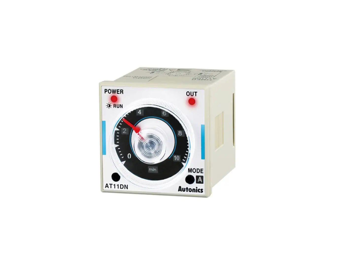
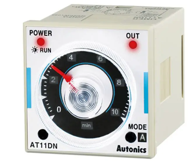
Autonics AT11DN W 48 × H 48 mm Analog Timers
Autonics ATN Series Catalog
The Autonics ATN Series Catalog is a multi-function timer used for various applications. The product comes with different models that have unique features and specifications.
Features
- Multi-function timer with different timing ranges
- Various input types including signal ON start and power ON start
- Different output modes such as instantaneous and time-limited DPDT or SPDT relays
- Compact design with transparent guide cover
Specifications
The specifications of the Autonics ATN Series Catalog are subject to change without notice for product improvement. Please follow the Autonics website to select the specific model based on your requirements.
| Model | Function | Return Time | Time Operation | Input | Output | Approval |
|---|---|---|---|---|---|---|
| AT8N- | Multi-Function Timer | 100 ms | Power ON Start, Signal ON Start | INHIBIT, START, RESET | Time limit DPDT (2c), Instantaneous SPDT (1c) + Time limit SPDT (1c) | – |
| AT11DN- | Multi-Function Timer | 100 ms | Power ON Start, Signal ON Start | INHIBIT, START, RESET | Time limit DPDT (2c) | – |
| AT11EN- | Multi-Function Timer | 100 ms | Power ON Start, Signal ON Start | INHIBIT, START, RESET | Instantaneous SPDT (1c) + Time limit SPDT (1c) | – |
Components
The Autonics ATN Series Catalog package includes the following components:
- Timer unit
- Bracket
- User manual/instruction guide
Usage Instructions
To use the Autonics ATN Series Catalog timer, follow these instructions:
- Connect the power input according to your model’s specifications.
- Select the desired time range using the time range setting switch and the dial for time setting.
- Select the desired output operation mode using the output operation mode setting switch.
- Connect the input signals using INHIBIT, START, and RESET terminals.
- Connect the load to the output relay contacts. Ensure that the load does not exceed the contact capacity.
- Power on the timer and start the input signal to activate the output relay according to your selected output operation mode.
For detailed specifications and further guidance on usage, refer to the user manual/instruction guide that comes with the product.
For any further assistance or support, please contact Autonics customer support.
For your safety, read and follow the considerations written in the instruction manual, other manuals and Autonics website.
The specifications, dimensions, etc. are subject to change without notice for product improvement. Some models may be discontinued without notice.
Product Features
- Wide range of power supply
: 100 – 240 VAC~ 50 / 60 Hz, 24 – 240 VDC~ / 24 VAC~ 50 / 60 Hz, 24 VDC /12 VDC - Various output operation (6 operation modes)
- Multi time range (16 types of time range)
- Wide control time (0.05 sec to 100 hour)
- Easy setting of time, time range, output operation mode
- Easy to check output status by indicator
Ordering Information
This is only for reference, the actual product does not support all combinations.
For selecting the specified model, follow the Autonics website.

- Plug type
8: 8-pin plug
11: 11-pin plug - Output
No mark: Time limit DPDT (2c), Instantaneous SPDT (1c) + Time limit SPDT (1c)
D: Time limit DPDT (2c)
E: Instantaneous SPDT (1c) + Time limit SPDT (1c) - Power supply
No mark: 100 – 240 VAC 50 / 60 Hz, 24 – 240 VDC
1: 12 VDC
2: 24 VAC 50 / 60 Hz, 24 VDC
Product Components
- Product (+ bracket)
- Instruction manual
Product Specifications
| Model | AT8N-□ | AT11DN-□ | AT11EN-□ |
| Function | Multi Function Timer | ||
| Return time | ≤ 100 ms | ||
| Time operation | Power ON Start | Signal ON Start | |
| Input | – | INHIBIT, START, RESET | |
| Min. signal width | – | ≈ 50 ms | |
| No-voltage input | – | Short-circuit impedance: ≤ 1 kΩ Short-circuit residual voltage: ≤ 0.5 VDC Open-circuit impedance: ≥ 100 kΩ | |
| Control output | Relay | ||
| Contact type | Time limit DPDT (2c), Time limit SPDT (1c) + Instantaneous SPDT (1c) | Time limit DPDT (2c) | Time limit SPDT (1c) + Instantaneous SPDT (1c) |
| Contact capacity | 250 VAC~ 5 A, 30 VDC resistive load | 250 VAC~ 5 A, 24 VDC resistive load | 250 VAC~ 5 A, 30 VDC resistive load |
| Error | Repeat: ≤ ± 0.2% ± 10 ms SET: ≤ ± 5% ± 50 ms Voltage: ≤ ± 0.5% Temp.: ≤ ± 2% | ||
| Approval | ᜢ ᜧ ᜫ | ||
| Unit weight (packaging) | ≈ 86.71 g (≈ 134.12 g) | ≈ 85 g (≈ 132.2 g) | ≈ 87.5 g (≈ 134.7 g) |
| Power supply | 100 – 240 VAC~ ± 10% 50 / 60 Hz, 24 – 240 VDC | 12 VDC | 24 VAC~ ± 10% 50 / 60 Hz, 24 VDC |
| Power consumption | It depends on the model. | ||
| AT8N-□ | AC: ≤ 4.3 VA DC: ≤ 2 W | DC: ≤ 1.5 W | AC: ≤ 4.5 VA DC: ≤ 2 W |
| AT11DN-□ | AC: ≤ 3.5 VA DC: ≤ 1.5 W | DC: ≤ 1 W | AC: ≤ 4 VA DC: ≤ 1.5 W |
| AT11EN-□ | AC: ≤ 4.3 VA DC: ≤ 2 W | DC: ≤ 1.5 W | AC: ≤ 4.5 VA DC: ≤ 2 W |
| Insulation resistive | ≥ 100 MΩ (500 VDC | ||
| Dielectric strength | 2,000 VAC~ 50 / 60 Hz for 1 min | ||
| Noise immunity | ± 2 kV square-wave noise by noise simulator (pulse width 1 ㎲) | ± 500 V square-wave noise by noise simulator (pulse width 1 ㎲) | |
| Vibration | 0.75 mm double amplitude at frequency of 10 to 55 Hz (for 1 min) in each X, Y, Z direction for 1 hour | ||
| Vibration (malfunction) | 0.5 mm double amplitude at frequency of 10 to 55 Hz (for 1 min) in each X, Y, Z direction for 10 min | ||
| Shock | 300 m/s2 (≈ 30 G) in each X, Y, Z direction for 3 times | ||
| Shock (malfunction) | 100 m/s2 (≈ 30 G) In each X, Y, Z direction for 3 times | ||
| Relay life cycle | Mechanical: ≥ 10,000,000 operations Electrical: ≥ 100,000 operations (250 VAC~ 5 A resistive load) | ||
| Ambient temperature | -10 to 55 ℃, storage: -25 to 65 ℃ (no freezing or condensation) | ||
| Ambient humidity | 35 to 85%RH, storage: 35 to 85%RH (no freezing or condensation) | ||
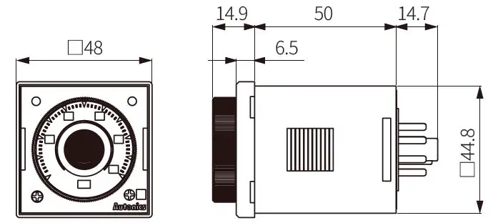
Dimensions
- Unit: mm, For the detailed drawings, follow the Autonics website.
Bracket

Panel cut-out

Unit Descriptions

| No. | Name |
| 1 | Power indicator |
| 2 | Time limit output indicator |
| 3 | Time range display part |
| 4 | Time range setting switch |
| 5 | Time unit display part • SEC, MIN, HOUR, 10H |
| 6 | Output operation mode setting switch |
| 7 | Output operation mode display part |
| 8 | Dial for the time setting |
Sold Separately
- 8-pin socket: PG-08, PS-08(N)
- 11-pin socket: PG-11, PS-11(N)
18, Bansong-ro 513Beon-gil, Haeundae-gu, Busan, Republic of Korea, 48002
www.autonics.com
+82-2-2048-1577
[email protected]


