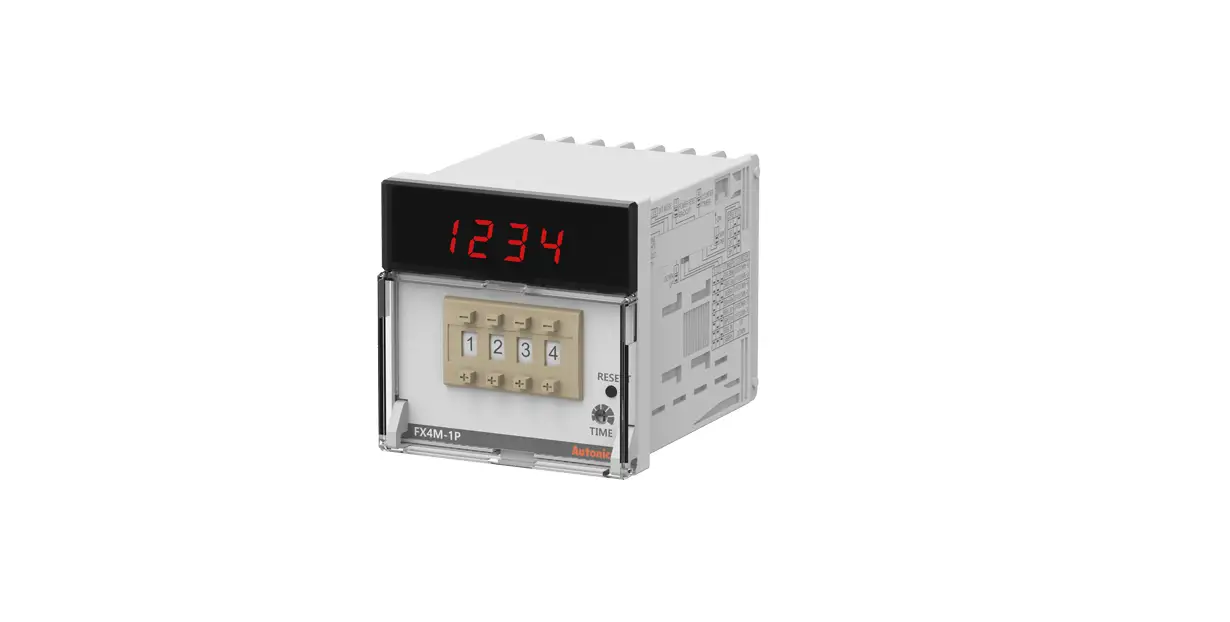
Autonics FXM/FXH Series Digital Counters Timers Instruction Manual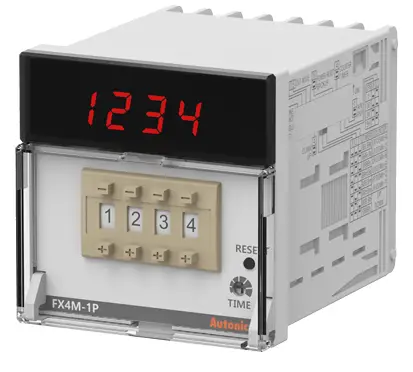
Thank you for choosing our Autonics product.
Read and understand the instruction manual and manual thoroughly before using the product.
For your safety, read and follow the below safety considerations before using.
For your safety, read and follow the considerations written in the instruction manual, other manuals and Autonics website.
Keep this instruction manual in a place where you can find easily.
The specifications, dimensions, etc. are subject to change without notice for product improvement. Some models may be discontinued without notice.
Follow Autonics website for the latest information.
Safety Considerations
- Observe all ‘Safety Considerations’ for safe and proper operation to avoid hazards.
 symbol indicates caution due to special circumstances in which hazards may occur.
![]() Warning: Failure to follow instructions may result in serious injury or death.
Warning: Failure to follow instructions may result in serious injury or death.
- . Fail-safe device must be installed when using the unit with machinery that may cause serious injury or substantial economic loss. (e.g. nuclear power control, medical equipment, ships, vehicles, railways, aircraft, combustion apparatus, safety equipment, crime / disaster prevention devices, etc.)
Failure to follow this instruction may result in personal injury, economic loss or fire. - Do not use the unit in the place where flammable / explosive / corrosive gas, humidity, direct sunlight, radiant heat, vibration, impact, or salinity may be present.
Failure to follow this instruction may result in explosion or fire. - Install on a device panel to use.
Failure to follow this instruction may result in fire or electric shock. - Do not connect, repair, or inspect the unit while connected to a power source.
Failure to follow this instruction may result in fire or electric shock. - Check ‘Connections’ before wiring.
Failure to follow this instruction may result in fire. - Do not disassemble or modify the unit.
Failure to follow this instruction may result in fire or electric shock
![]() Caution: Failure to follow instructions may result in injury or product damage.
Caution: Failure to follow instructions may result in injury or product damage.
- When connecting the power / sensor input and relay output, use AWG 20
(0.50 mm2 ) cable or over, and tighten the terminal screw with a tightening torque of 0.74 to 0.90 N m.
Failure to follow this instruction may result in fire or malfunction due to contact failure. - Use the unit within the rated specifications.
Failure to follow this instruction may result in fire or product damage. - Use a dry cloth to clean the unit, and do not use water or organic solvent.
Failure to follow this instruction may result in fire or electric shock. - Keep the product away from metal chip, dust, and wire residue which flow into the unit.
Failure to follow this instruction may result in fire or product damage.
Cautions during Use
- Follow instructions in ‘Cautions during Use’.
Otherwise, it may cause unexpected accidents. - Use the product, 0.1 sec after supplying power.
- When supplying or turning off the power, use a switch or etc. to avoid chattering.
- Install a power switch or circuit breaker in the easily accessible place for supplying or disconnecting the power.
- When the counter is operating, in case of contact input, set count speed to low speed mode (1 cps or 30 cps) to operate. If set to high speed mode (2 k, 5 kcps) counting error occurs due to chattering.
- Keep away from high voltage lines or power lines to prevent inductive noise. In case installing power line and input signal line closely, use line filter or varistor at power line and shielded wire at input signal line.
Do not use near the equipment which generates strong magnetic force or high
frequency noise. - This unit may be used in the following environments.
- Indoors (in the environment condition rated in ‘Specifications’)
- Altitude max. 2,000 m
- Pollution degree 2
- Installation category I
Ordering Information
This is only for reference, the actual product does not support all combinations.
For selecting the specified model, follow the Autonics webstie.
FX ❶ ❷ – ❸ 4
- Display digits
4: 4-digit
6: 6-digit
8: 8-digit - Size
M: DIN W 72 × H 72 mm
H: DIN W 48 × H 96 mm - Output
1P: 1-stage setting
2P: 2-stage setting
I: Indicator
Product Components
- Product (+ bracket)
- Instruction manual
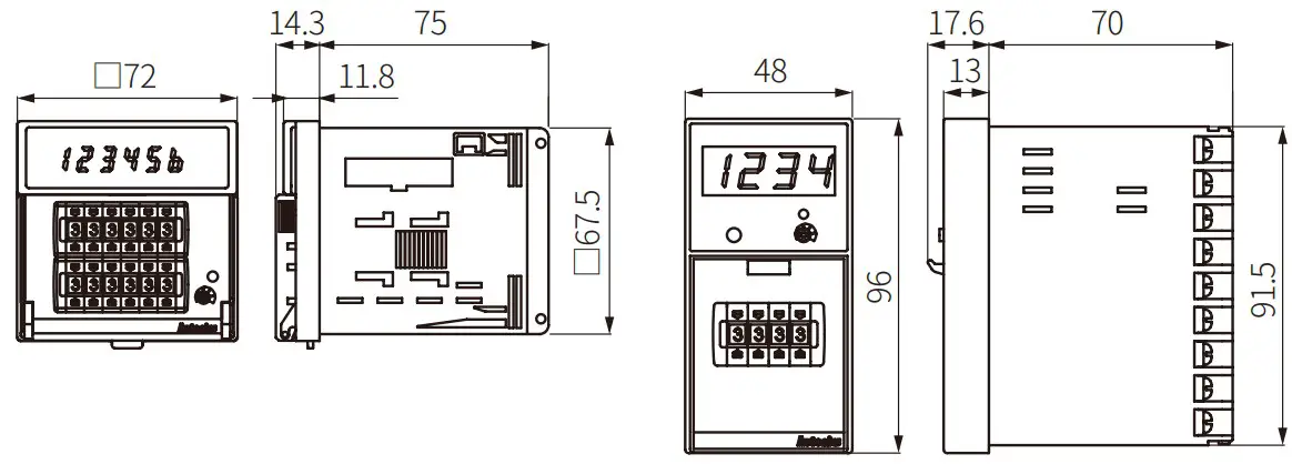
Dimensions
Unit: mm, For the detailed drawings, follow the Autonics website.
- FXM
- FXH

- Bracket
- Panel cut-out

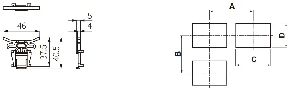
| Series | A | B | C | D |
| FXM | ≥ 90 | ≥ 90 | 68+0.70 | 68+0.70 |
| FXH | ≥ 65 | ≥ 115 | 45+0.60 | 92+0.80 |
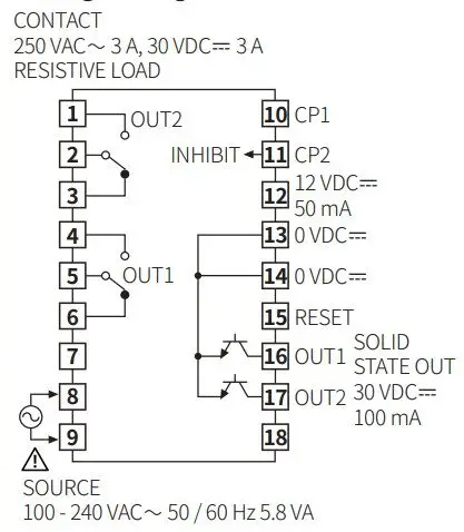
Connections
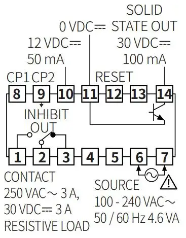
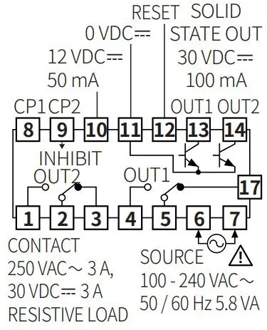
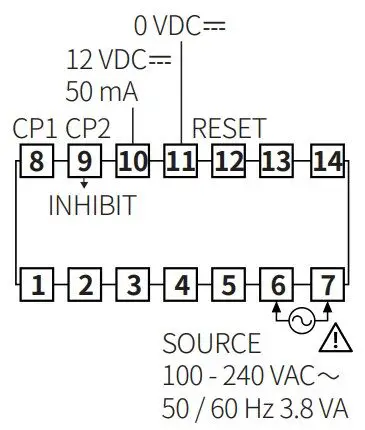
- FX□M
- 1-stage setting model

- 2-stage setting model

- Indicator model

- 1-stage setting model
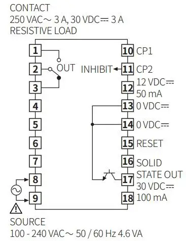
- FX4H
- 1-stage setting model

- 2-stage setting model

- 1-stage setting model
- INHIBIT: In case of timer mode, this terminal is for time hold.
- Voltage input (PNP): connect with 12 VDCᜡ
- No-voltage input (NPN): connect with 0 VDCᜡ
Specifications
| Model | FX4□-□4 | FX6M-□4 | FX8M-□4 |
| Display digits | 4-digit | 6-digit | 8-digit |
| Character size | W 6 × H 10 mm | W 4 × H 8 mm | W 3.8 × H 7.6 mm |
| Max. counting speed | 1 / 30 / 2 k / 5 k cps | ||
| Return time | ≤ 500 ms | ||
| Min. signal width | INHIBIT, RESET: ≈ 20 ms | ||
| Input logic | Voltage input (PNP) – input impedance: ≤ 10.8 kΩ,[H]: 5 – 30 VDCᜡ, [L]: 0 – 2 VDCᜡNo-voltage input (NPN) – short-circuit impedance: ≤ 470 Ω,short-circuit residual voltage: ≤ 1 VDCᜡ open-circuit impedance: ≥ 100 kΩ | ||
| One-shot output time | Dependent on the output | ||
| 1-stage setting | 0.05 to 5 sec | ||
| 2-stage setting | OUT1: 0.5 sec fixed, OUT2: 0.05 to 5 sec | ||
| Error | Repeat / SET / voltage / Temp.: ≤ ± 0.01 % ± 0.05 s | ||
| Contact control output | Relay | ||
| Type (1-stage) | Instantaneous SPDT (1c) × 1 | ||
| Type (2-stage) | Instantaneous SPDT (1c) × 2 | ||
| Capacity | 250 VACᜠ 3 A, 30 VDCᜡ 3 A resistive load | ||
| Solid-state control output | NPN open collector | ||
| Type (1-stage) | × 1 | ||
| Type (2-stage) | × 2 | ||
| Capacity | ≤ 30 VDCᜡ, 100 mA, residual voltage: ≤ 1 VDCᜡ | ||
| Unit weight (packaged) | 1-stage setting: ≈ 180 g (≈ 245 g) 2-stage setting: ≈ 200 g (≈ 265 g) Indicator: ≈ 160 g (≈ 225 g) | ||
| Approval | |||
| Power supply | 100 – 240 VACᜠ ± 10 % 50 / 60 Hz |
| Power consumption | Dependent on the output |
| 1-stage setting | ≤ 4.6 VA |
| 2-stage setting | ≤ 5.8 VA |
| Indicator | ≤ 3.8 VA |
| External supply power | ≤ 12 VDCᜡ ± 10 % 50 mA |
| Memory retention | ≈ 10 years (non-volatile semiconductor memory type) |
| Insulation resistance | ≥ 100 MΩ (500 VDCᜡ megger) |
| Dielectric strength | Between all terminals and case: 2,000 VACᜠ 50 / 60 Hz for 1 min |
| Noise immunity | ± 2 kV square wave noise (pulse width: 1 ㎲) by the noise simulator |
| Vibration | 0.75 mm double amplitude at frequency of 10 to 55 Hz (for 1 minute) in each X, Y, Z direction for 1 hour |
| Vibration (malfunction) | 0.5 mm double amplitude at frequency of 10 to 55 Hz (for 1 minute) in each X, Y, Z direction for 10 minute |
| Shock | 300 m/s2 (≈ 30 G) in each X, Y, Z direction for 3 times |
| Shock (malfunction) | 100 m/s2 (≈ 10 G) in each X, Y, Z direction for 3 times |
| Relay life cycle | Mechanical: ≥ 10,000,000 operationsElectrical: ≥ 100,000 operations (250 VACᜠ 3 A resistive load) |
| Ambient temperature | -10 to 55 ℃, storage: -25 to 65 ℃ (no freezing or condensation) |
| Ambient humidity | 35 to 85 %RH, storage: 35 to 85 %RH (no freezing or condensation) |
| Protection rating | IP20 (front part, IEC standard) |
Mode Setting
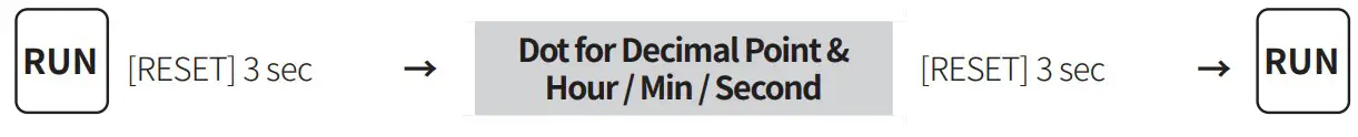
Dot for Decimal Point & Hour / Min / Second
- If there is no RESET key or DIP switch input for 60 sec, it returns to RUN mode.
- [RESET] key: Setting mode ↔ RUN mode
Move the digit when changing the setting value.
Decimal point of counter
| Parameter | Display | Setting range | |
| C1-1 | Setting mode | – | |
| —- | [FX4□-□4] —-, —.-, –.–, -.— | ||
| C1-2 | Decimal point setting | —— | [FX6M-□4] ——, —–.-, —-.–, —.—, –.—-, -.—– |
| ——– | [FX8M-□4] ——–, ——-.-, ——.–, —–.—,————-,——— ,—.—–, –.——, -.——- | ||
Dot for Hour / Min / Second of timer
| Parameter | Display | Setting range | Setting example | |
| T1-1 | Setting mode | – | – | |
| T1-2 | Setting of dot for Hour / Min / Sec | CLR: Not divided with dot | 5959: 59 m 59 s | |
| SET: Divided with dot | 0.59.59: 59 m 59 s | |||
Error
- When error occurs, the output turns OFF.
- When 1-stage setting value = 0, OUT1 turns OFF.
When 2-stage setting value < 1-stage setting value, OUT1 is ignored and only OUT2 operates. - Indicator model does not have error display function.
| Display | Description | Troubleshooting |
| Setting value = 0 | Change the setting value anything but 0. |
Output Operation Mode
For the detailed timing chart for operation output mode, refer to the manual.
Detach the Case or DIP Switch Cover
- FXM

- Push and pull the groove of DIP switch cover with a flat head (-) driver to the front, detaching the cover from the case.
- FXH

- Push the groove of the front guide with a flat head (-) driver and pull it to the front.
- Pull the front guide to the front. The case is detached. DIP switch is located inside.
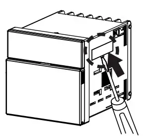
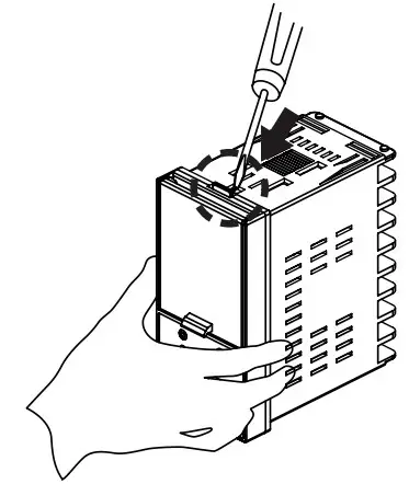
![]() Caution: Turn OFF the power before detaching the cover or case.
Caution: Turn OFF the power before detaching the cover or case.![]() Caution: When using the tools, be careful not to be wounded.
Caution: When using the tools, be careful not to be wounded.
DIP Switch Setting
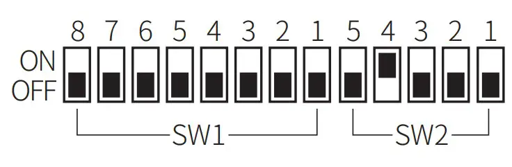
- Detach the case or cover of DIP switch and proceed the settings. See the ‘Detach the Case or DIP Switch Cover.’
- How to change the settings: power OFF → change settings → power ON → press [RESET] key or input the RESET signal (≥ 20 ms) to the external terminal.
DIP SW1
| SW1 | Function | Defaults | |
| Counter | Timer | ||
| 1 | – | Time range | OFF |
| 2 | Input operation mode | OFF | |
| 3 | OFF | ||
| 4 | Count up / count down | OFF | |
| 5, 6, 7 | Output operation mode 01) | OFF | |
| 8 | OUT1 One-shot output 02) | OFF | |
- Except the indicator model.
- Only for 2-stage setting model.
DIP SW2
| SW2 | Function | Defaults | |
| Counter | Timer | ||
| 1 | CP1, CP2, INHIBIT, RESETinput logic | OFF | |
| 2 | Max. counting speed | – | OFF |
| 3 | OFF | ||
| 4 | Counter / Timer | ON | |
| 5 | Memory retention | OFF | |
[Counter] Input operation mode
| SW1 | Count up / count down & input operation mode | |||
| 4 | 3 | 2 | ||
| OFF | OFF | OFF | Count up | Up / Down – A (command) |
| OFF | OFF | ON | Up / Down – B (individual) | |
| OFF | ON | OFF | Up / Down – C (phase difference) | |
| OFF | ON | ON | UP | |
| ON | OFF | OFF | Count down | Up / Down – D (command) |
| ON | OFF | ON | Up / Down – E (individual) | |
| ON | ON | OFF | Up / Down – F (phase difference) | |
| ON | ON | ON | Down | |
Output operation mode (1-stage / 2-stage setting model)
| SW1 | Output operation mode | ||
| 7 | 6 | 5 | |
| OFF | OFF | OFF | F |
| OFF | OFF | ON | N |
| OFF | ON | OFF | C |
| OFF | ON | ON | R |
| ON | OFF | OFF | K |
| ON | OFF | ON | P |
| ON | ON | OFF | Q |
| ON | ON | ON | S |
OUT1 One-shot output (2-stage setting model)
| SW1-8 | OUT1 One-shot output |
| ON | One-shot |
| OFF | Hold |
[Timer] Time range
| SW1 | Time range | ||||
| 3 | 2 | 1 | 4-digit | 6-digit | 8-digit |
| OFF | OFF | OFF | 99.99 s | 99999.9 s | 999999.99 s |
| OFF | OFF | ON | 999.9 s | 999999 s | 9999999.9 s |
| OFF | ON | OFF | 9999 s | 99 m 59.99 s | 99999999 s |
| OFF | ON | ON | 99 m 59 s | 999 m 59.9 s | 99999 m 59.9 s |
| ON | OFF | OFF | 999.9 m | 99999.9 m | 9999999.9 m |
| ON | OFF | ON | 99 h 59 m | 99 h 59 m 59 s | 999 h 59 m 59.9 s |
| ON | ON | OFF | 999.9 h | 9999 h 59 m | 9999 h 59 m 59 s |
| ON | ON | ON | 9999 h | 99999.9 h | 99999 h 59.9 m |
Input logic
| SW2-1 | Input logic |
| ON | NPN (no-voltage input) |
| OFF | PNP (voltage input) |
Counter / Timer
| SW2-4 | Counter / Timer |
| ON | Counter |
| OFF | Timer |
[Counter] Max. counting speed
| SW2 | Max. counting speed | |
| 3 | 2 | |
| OFF | ON | 1 cps |
| OFF | OFF | 30 cps |
| ON | OFF | 2 kcps |
| ON | ON | 5 kcps |
Memory retention
| SW2-5 | Memory retention |
| ON | × |
| OFF | ○ |
18, Bansong-ro 513Beon-gil, Haeundae-gu, Busan, Republic of Korea, 48002
www.autonics.com | +82-2-2048-1577 | [email protected]