![]()
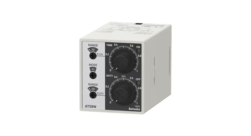
W 38 × H 42 mm Twin Analog Timers
Ordering Information
ATS8W / ATS11W Series
INSTRUCTION MANUAL
ATS8W W38x H42mm Twin Analog Timers
Thank you for choosing our Autonics product.
Read and understand the instruction manual and manual thoroughly before using the product.
For your safety, read and follow the below safety considerations before using.
For your safety, read and follow the considerations written in the instruction manual, other manuals and Autonics website.
Keep this instruction manual in a place where you can find easily.
The specifications, dimensions, etc. are subject to change without notice for product improvement. Some models may be discontinued without notice.
Follow Autonics website for the latest information.
Safety Considerations
- Observe all ‘Safety Considerations’ for safe and proper operation to avoid hazards.
 symbol indicates caution due to special circumstances in which hazards may occur.
![]() Warning Failure to follow instructions may result in serious injury or death.
Warning Failure to follow instructions may result in serious injury or death.
- Fail-safe device must be installed when using the unit with machinery that may cause serious injury or substantial economic loss. (e.g. nuclear power control, medical equipment, ships, vehicles, railways, aircraft, combustion apparatus, safety equipment, crime/disaster prevention devices, etc.) Failure to follow this instruction may result in personal injury, economic loss or fire.
- Do not use the unit in the place where flammable/explosive/corrosive gas, high humidity, direct sunlight, radiant heat, vibration, impact or salinity may be present.
Failure to follow this instruction may result in explosion or fire. - Install on a device panel to use. Failure to follow this instruction may result in fire or electric shock.
- Do not connect, repair, or inspect the unit while connected to a power source. Failure to follow this instruction may result in fire or electric shock.
- Check ‘Connections’ before wiring. Failure to follow this instruction may result in fire.
- Do not disassemble or modify the unit. Failure to follow this instruction may result in fire or electric shock.
![]() Caution Failure to follow instructions may result in injury or product damage.
Caution Failure to follow instructions may result in injury or product damage.
- Use the unit within the rated specifications. Failure to follow this instruction may result in fire or product damage.
- Use a dry cloth to clean the unit, and do not use water or organic solvent. Failure to follow this instruction may result in fire or electric shock.
- Keep the product away from metal chip, dust, and wire residue which flow into the unit. Failure to follow this instruction may result in fire or product damage.
Cautions during Use
- Follow instructions in ‘Cautions during Use’. Otherwise, it may cause unexpected accidents.
- Power supply should be insulated and limited voltage/current or Class2, SELV power supply device.
- When supplying or turning off the power, use a switch or etc. to avoid chattering.
- Install a power switch or circuit breaker in the easily accessible place for supplying or disconnecting the power.
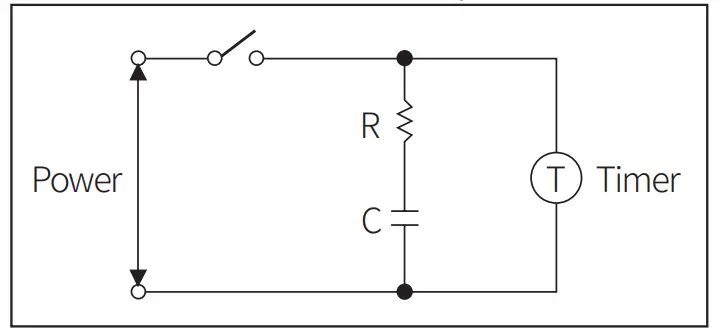
- In order to avoid leakage current flowing, connect resistance and condenser like below. Otherwise, it may cause malfunction.
- Do not connect two or more timers with only one input contact or transistor simultaneously.
- After turning off the power, change the time range, etc.
- Keep away from high voltage lines or power lines to prevent inductive noise. In case installing power line and input signal line closely, use line filter or varistor at power line and shielded wire at input signal line. Do not use near the equipment which generates strong magnetic force or high frequency noise.
- This unit may be used in the following environments.
– Indoors (in the environment condition rated in ‘Specifications’)
– Altitude max. 2,000 m
– Pollution degree 2
– Installation category II
Ordering Information
This is only for reference, the actual product does not support all combinations.
For selecting the specified model, follow the Autonics website.
ATS ❶ W – ❷ ❸
❶ Plug type
8: 8-pin plug
11: 11-pin plug
❷ Power supply
1: 12 VDC![]()
2: 24 VAC∼ 50 / 60 Hz, 24 VDC![]()
4: 100 – 240 VAC∼ 50 / 60 Hz, 24 – 240 VDC![]()
❸ Time range
1: 0.1 to 1
3: 0.3 to 3
Product Components
- Product (+ bracket)
- Instruction manual
Sold Separately
- 8-pin socket: PG-08, PS-08(N), PS-M8
- 11-pin socket: PG-11, PS-11(N)
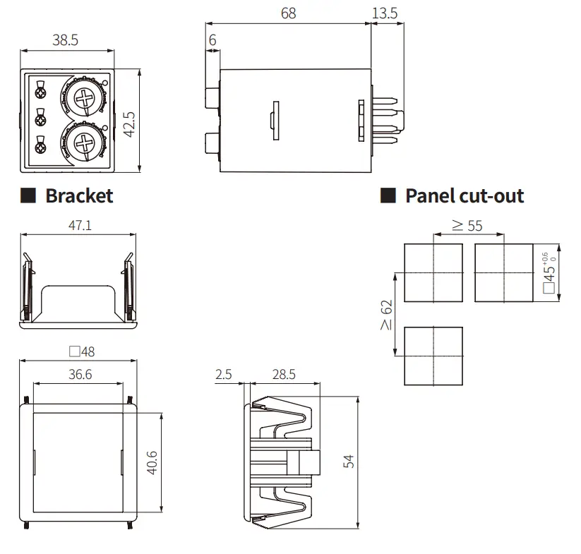
Dimensions
- Unit: mm, For the detailed drawings, follow the Autonics website.
Unit Descriptions
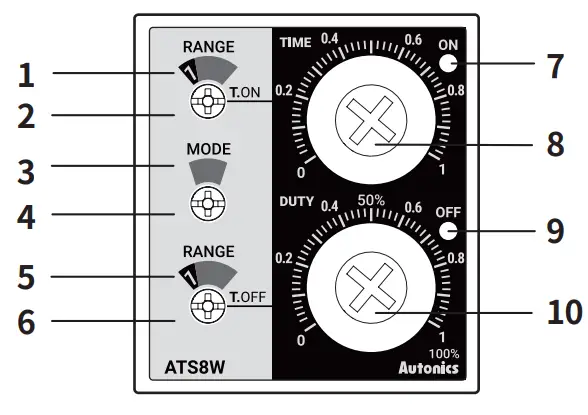
| No. | Name |
| 1 | ON time range display part |
| 2 | ON time setting switch |
| 3 | Output operation mode display part |
| 4 | Output operation mode setting switch |
| 5 | OFF time range display part |
| 6 | OFF time range setting switch |
| 7 | ON operation indicator (red) |
| 8 | ON time dial |
| 9 | OFF operation indicator (green) |
| 10 | Dial for OFF time / ON Duty |
Output Operation Mode
For the detailed timing chart for operation output mode, refer to the manual.
| F1 | Flicker 1 (OFF Start) |
| F2 | Flicker 2 (OFF Start) |
| F3 01) | Flicker 3 (OFF Start) |
| N1 | Flicker 1 (ON Start) |
| N2 | Flicker 2 (ON Start) |
| N3 01 | Flicker 3 (ON Start) |
01) The modes are Flicker operation with setting the TIME and DUTY.
ON time range is changed to TIME range and OFF time range is changed to DUTY range.
| ON / OFF time range display part | Unit | Range | |
| ATS❑W-❑1 | ATS❑W-❑3 | ||
| ls | SEC | 0.1 to 1 | 0.3 to 3 |
| 10S | I to 10 | 3 to 30 | |
| 1M | MIN | al to 1 | 0.3 to 3 |
| 10M | I to 10 | 3 to 30 | |
| 1H | HOUR | 0.1 to 1 | 0.3 to 3 |
| 10H | I to 10 | 3 to 30 | |
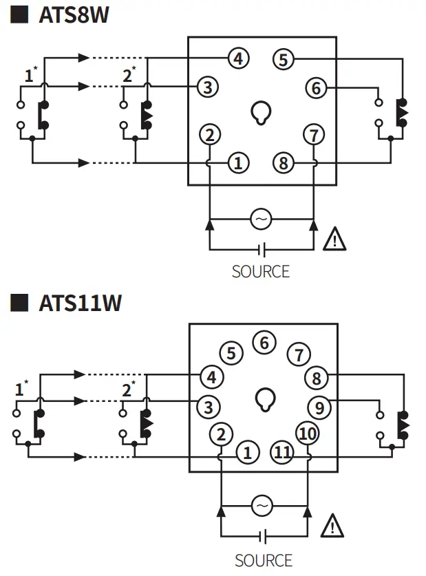
Connections
![]() Caution
Caution
: Refer to the ‘specifications’ for checking the power supply and control output.
• 1* : output operation mode – F2, N2
• 2* : output operation mode – F1, F3, N1, N3
Specifications
| Model | ATSLIW-10 | ATS❑W-20 | ATS❑W-4❑ |
| Function | ON / OFF Flicker operation | ||
| Retum time | ≤ 100 ms | ||
| Time operation | Power ON Start | ||
| Control output | Relay | ||
| Contact type | Time limit DPDT (2c), Instantaneous SPDT (1c) + Time limit SPDT (1c) | ||
| Contact capacity | 250 VAC∼ 3 A, 30 VDC | ||
| Error | Repeat: ≤ ± 0.2% ± 10 ms SET: ≤ ± 5% ± 50 ms Voltage: ≤ ± 0.5% Temp.: ≤ ± 2% | ||
| Approval | |||
| Unit weight (packaged) | ≈ 75 g (≈ 100 g) | ||
| Power supply | 12 VDC | 24 VAC∼ ± 10% 50 / 60 Hz, 24 VDC | 100 – 240 VAC∼ ± 100/0 50/60 Hz, 24-240VDC |
| Power consumption | DC: ≤ 1.5 W | AC: ≤ 4.5 VA DC: ≤ 2 W | AC: ≤ 4.2 VA DC: ≤ 2 W |
| Insulation resistive | ≥ 100 MΩ (500 VDC | ||
| Dielectric strength | 2,000 VAC∼ at 50/60 Hz for 1 min | ||
| Noise immunity | ± 500 V square-wave noise by noise simulator (pulse width 1 us) | ± 2kV square-wave noise by noise simulator (pulse width 1 ps) | |
| Vibration | 0.75 mm double amplitude at frequency of 10 to 55 Hz (for 1 min) in each X, Y, Z direction for 1 hour | ||
| Vibration(malfunction) | .0 5 mm double amplitude at frequency of 10 to 55 Hz (for 1 min) in each X, Y, Z direction for 10 min | ||
| Shock | 300 m/s2 (≈ 30 G) in each X, Y, Z direction for 3 times | ||
| Shock (malfunction) | 100 m/s2 (≈ 10 G) In each X, Y, Z direction for 3 times | ||
| Relay life cycle | Mechanical: ≥ 10,000,000 operations Electrical: ≥ 100,000 operations (250 VAC∼ 3 A resistive load) | ||
| Ambient temperature | -10 to 55 °C, storage: -25 to 65 °C (no freezing or condensation) | ||
| Ambient humidity | 35 to 85%RH, storage: 35 to 85%RH (no freezing or condensation) | ||
![]()
18, Bansong-ro 513Beon-gil, Haeundae-gu, Busan, Republic of Korea, 48002
www.autonics.com | +82-2-2048-1577 | [email protected]


