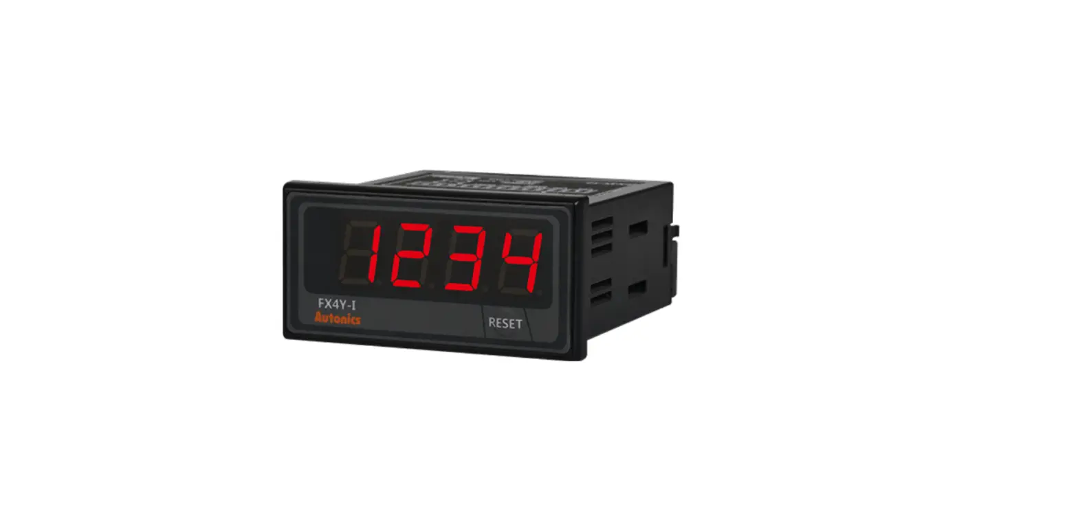
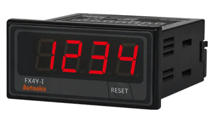
Autonics FXY Series Digital Counters or Timers Indicator
Features
- Counting speeds: 1 cps / 30 cps / 2 kcps / 5 kcps
- Switch between counter and timer operation using DIP switch
- Switch between voltage input (PNP) and no-voltage input (PNP) using DIP switch
- Set decimal point, hr / min / sec display with RESET key
- Operation modes: count-up, count-down, count-up / down (counter)
[Counter]
- 20 input modes
[Timer]
- Various time-setting ranges
- 6-digit models: 0.01 sec to 99999.9 hr
- 4-digit models: 0.01 sec to 9999 hr
- Power supply
- 100 – 240 VAC 50 / 60 Hz (AC type)
- 24 VAC 50 / 60 Hz, 24 – 48 VDC (AC / DC universal type)
Safety Considerations
- Observe all ‘Safety Considerations’ for safe and proper operation to avoid hazards.
- symbol indicates caution due to special circumstances in which hazards may occur.
Warning Failure to follow instructions may result in serious injury or death.
- Fail-safe device must be installed when using the unit with machinery that may cause serious injury or substantial economic loss. (e.g. nuclear power control, medical equipment, ships, vehicles, railways, aircraft, combustion apparatus, safety equipment, crime / disaster prevention devices, etc.) Failure to follow this instruction may result in personal injury, economic loss or fire.
- Do not use the unit in the place where flammable / explosive / corrosive gas, humidity, direct sunlight, radiant heat, vibration, impact, or salinity may be present.
- Failure to follow this instruction may result in explosion or fire.
- Install on a device panel to use.
- Failure to follow this instruction may result in fire or electric shock.
- Do not connect, repair, or inspect the unit while connected to a power source.
- Failure to follow this instruction may result in fire or electric shock.
- Check ‘Connections’ before wiring.
- Failure to follow this instruction may result in fire.
- Do not disassemble or modify the unit.
- Failure to follow this instruction may result in fire or electric shock.
Caution Failure to follow instructions may result in injury or product damage.
- When connecting the power/sensor input, use AWG 20 (0.50 mm2) cable or over, and tighten the terminal screw with a tightening torque of 0.74 to 0.90 N m.
Failure to follow this instruction may result in fire or malfunction due to contact failure. - Use the unit within the rated specifications.
Failure to follow this instruction may result in fire or product damage. - Use a dry cloth to clean the unit, and do not use water or organic solvent. Failure to follow this instruction may result in fire or electric shock.
- Keep the product away from metal chips, dust, and wire residue which flow into the unit.
Failure to follow this instruction may result in fire or product damage.
Cautions during Use
- Follow instructions in ‘Cautions during Use’.
- Otherwise, it may cause unexpected accidents.
- Power supply should be insulated and limited voltage / current or Class 2, SELV power supply device.
- Use the product, 0.1 sec after supplying power.
- When supplying or turning off the power, use a switch or etc. to avoid chattering.
- Install a power switch or circuit breaker in the easily accessible place for supplying or disconnecting the power.
- When the counter is operating, in case of contact input, set count speed to low speed mode (1 cps or 30 cps) to operate. If set to high speed mode (2 k, 5 kcps) counting error occurs due to chattering.
- Keep away from high voltage lines or power lines to prevent inductive noise. In case installing power line and input signal line closely, use line filter or varistor at power line and shielded wire at input signal line.
- Do not use near the equipment which generates strong magnetic force or high frequency noise.
- This unit may be used in the following environments.
- Indoors (in the environment condition rated in ‘Specifications’)
- Altitude max. 2,000 m
- Pollution degree 2
- Installation category II
Ordering Information
This is only for reference, the actual product does not support all combinations. For selecting the specified model, follow the Autonics webstie. ![]()
- Display digits
- 4: 4-digit
6: 6-digit
- 4: 4-digit
- Power supply
- 2: 24 VAC ± 10 % 50 / 60 Hz,
- 24 – 48 VDC ± 10 %
- 4: 100 – 240 VAC ± 10 % 50 / 60 Hz
Product Components
- Product
- Bracket × 2
- Instruction manual
Dimensions
Unit: mm, For the detailed drawings, follow the Autonics website.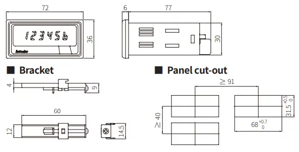
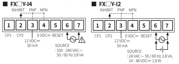
Connections
Specifications
| Model | FX4Y-I□ | FX6Y-I□ |
| Display digits | 4-digit | 6-digit |
| Character size | W 8 × H 14 mm | W 4 × H 8 mm |
| Max. counting speed | 1 / 30 / 2 k / 5 k cps | |
| Return time | ≤ 500 ms | |
| Min. signal width | INHIBIT, RESET: ≈ 20 ms | |
|
Input logic | Voltage input (PNP) – input impedance: ≤ 10.8 kΩ, [H]: 5 – 30 VDC, [L]: 0 – 2 VDC No-voltage input (NPN) – short-circuit impedance: ≤ 470 Ω, short-circuit residual voltage: ≤ 1 VDC open-circuit impedance: ≥ 100 kΩ | |
| Error | Repeat / SET / voltage / Temp.: ≤ ± 0.01 % ± 0.05 s | |
| Unit weight (packaged) | ≈ 120 g (≈ 175 g) | |
| Approval | ||
| Voltage type | AC voltage | AC / DC voltage |
| Power supply | 100 – 240 VAC ± 10 % 50 / 60 Hz | 24 VAC ± 10 % 50 / 60 Hz, 24 – 48 VDC ± 10 % |
| Power consumption | ≤ 3.8 VA | AC: ≤ 2.8 VA DC: ≤ 1.8 W |
| External supply power | ≤ 12 VDC ± 10 % 50 mA | |
| Memory retention | ≈ 10 years (non-volatile semiconductor memory type) | |
| Insulation resistance | ≥ 100 MΩ (500 VDC megger) | |
| Dielectric strength | Between all terminals and case: 2,000 VAC 50 / 60 Hz for 1 min | |
| Noise immunity | ± 2 kV square wave noise (pulse width: 1 ㎲) by the noise simulator | ± 500 V square wave noise (pulse width: 1 ㎲) by the noise simulator |
| Vibration | 0.75 mm double amplitude at frequency of 10 to 55 Hz (for 1 minute) in each X, Y, Z direction for 1 hour | |
| Vibration (malfunction) | 0.5 mm double amplitude at frequency of 10 to 55 Hz (for 1 minute) in each X, Y, Z direction for 10 minute | |
| Shock | 300 m/s2 (≈ 30 G) in each X, Y, Z direction for 3 times | |
| Shock (malfunction) | 100 m/s2 (≈ 10 G) in each X, Y, Z direction for 3 times | |
| Ambient temperature | -10 to 55 ℃, storage: -25 to 65 ℃ (no freezing or condensation) | |
| Ambient humidity | 35 to 85 %RH, storage: 35 to 85 %RH (no freezing or condensation) | |
| Protection rating | IP40 (front part, IEC standard) | |
Mode Setting
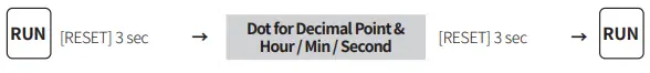
Dot for Decimal Point & Hour / Min / Second
- If there is no RESET key or DIP switch input for 60 sec, it returns to RUN mode.
- [RESET] key: Setting mode ↔ RUN mode Move the digit when changing the setting value.
The decimal point of counter
| Parameter | Display | Setting range | |
| C1-1 | Setting mode | DP | – |
| C1-2 | Decimal point setting | —- | [FX4Y-I□] —-, —.-, –.–, -.— |
| —— | [FX6Y-I□] ——, —–.-, —-.–, —.—, –.—-, -.—– | ||
Dot for Hour / Min / Second of timer
| Parameter | Display | Setting range | Setting example | |
| T1-1 | Setting mode | DP | – | – |
| T1-2 | The setting of dot for Hour / Min / Sec | CLR | CLR: Not divided with a dot | 5959: 59 m 59 s |
| SET: Divided with dot | 0.59.59: 59 m 59 s | |||
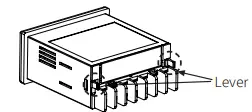
Detach the Case
- Press both levers and pull them from the front to detach the case and the terminal. DIP switch is located inside.
- Caution: Turn OFF the power before detaching the case.

DIP Switch Setting
- Detach the case and proceed the settings. See the ‘Detach the Case.’ How to change the settings:
- power OFF → change settings → power ON → press [RESET] key or input the RESET signal (≥ 20 ms) to the external terminal.

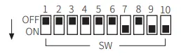
| SW | Function | Defaults | |
| Counter | Timer | ||
| 1 | – | Time range | OFF |
| 2 | Input operation mode | OFF | |
| 3 | OFF | ||
| 4 | Count up / count down | OFF | |
| 5 | Max. counting speed | – | OFF |
| 6 | OFF | ||
| 7 | Front [RESET] key | ON | |
| 8 | Memory retention | OFF | |
| 9 | Counter / Timer | ON | |
| 10 | CP1, CP2, INHIBIT, RESET input logic | ON | |
[Counter] Input operation mode
| SW | Count up / count down & input operation mode | |||
| 2 | 3 | 4 | ||
| OFF | OFF | OFF |
Count up | Up / Down – A (command) |
| ON | OFF | OFF | Up / Down – B (individual) | |
| OFF | ON | OFF | Up / Down – C (phase difference) | |
| ON | ON | OFF | UP | |
| OFF | OFF | ON |
Count down | Up / Down – D (command) |
| ON | OFF | ON | Up / Down – E (individual) | |
| OFF | ON | ON | Up / Down – F (phase difference) | |
| ON | ON | ON | Down | |
[Counter] Max. counting speed
| SW | Max. counting speed | |
| 5 | 6 | |
| ON | OFF | 1 cps |
| OFF | OFF | 30 cps |
| OFF | ON | 2 kcps |
| ON | ON | 5 kcps |
Front [RESET] key
| SW-7 | Front [RESET] key |
| ON | Use |
| OFF | Not used |
Counter / Timer
| SW-9 | Counter / Timer |
| ON | Counter |
| OFF | Timer |
[Timer] Time range
| SW | Time range | |||
| 1 | 2 | 3 | 4-digit | 6-digit |
| OFF | OFF | OFF | 99.99 s | 99999.9 s |
| ON | OFF | OFF | 999.9 s | 999999 s |
| OFF | ON | OFF | 9999 s | 99 m 59.99 s |
| ON | ON | OFF | 99 m 59 s | 999 m 59.9 s |
| OFF | OFF | ON | 999.9 m | 99999.9 m |
| ON | OFF | ON | 99 h 59 m | 99 h 59 m 59 s |
| OFF | ON | ON | 999.9 h | 9999 h 59 m |
| ON | ON | ON | 9999 h | 99999.9 h |
Memory retention
| SW-8 | Memory retention |
| ON | × |
| OFF | ○ |
Input logic
| SW-10 | Input logic |
| ON | NPN (no-voltage input) |
| OFF | PNP (voltage input) |
Input Connections
- Input: CP1, CP2 (INHIBIT), RESET
- Max. counting speed in the contact input: 1 or 30 cps setting (counter).
No-voltage (NPN) input
Solid-state input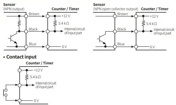
Voltage (PNP) input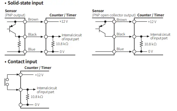
Counter Operation
Input operation mode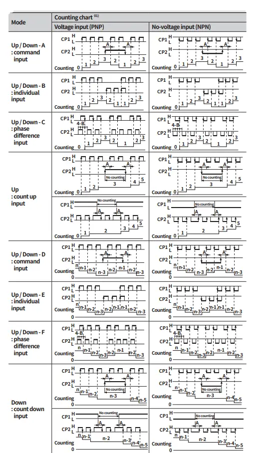
- CP: clock pulse, n: +max. display value
- A should be over min. signal width, B is over 1 / 2 of min. signal width. If the signal is smaller than these widths, it may cause a counting error (± 1).
Counting operation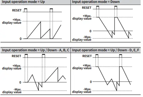
Timer Operation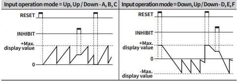
Segment Table
The segments displayed on the product indicate the following meanings. It may differ depending on the product
| 7 segment | |||
| 0 | 0 | I | I |
| 1 | 1 | J | J |
| 2 | 2 | K | K |
| 3 | 3 | L | L |
| 4 | 4 | M | M |
| 5 | 5 | N | N |
| 6 | 6 | O | O |
| 7 | 7 | P | P |
| 8 | 8 | Q | Q |
| 9 | 9 | R | R |
| A | A | S | S |
| B | B | T | T |
| C | C | U | U |
| D | D | V | V |
| E | E | W | W |
| F | F | X | X |
| G | G | Y | Y |
| H | H | Z | Z |
| 11 segment | |||
| 0 | 0 | I | I |
| 1 | 1 | J | J |
| 2 | 2 | K | K |
| 3 | 3 | L | L |
| 4 | 4 | M | M |
| 5 | 5 | N | N |
| 6 | 6 | O | O |
| 7 | 7 | P | P |
| 8 | 8 | Q | Q |
| 9 | 9 | R | R |
| A | A | S | S |
| B | B | T | T |
| C | C | U | U |
| D | D | V | V |
| E | E | W | W |
| F | F | X | X |
| G | G | Y | Y |
| H | H | Z | Z |
| 16 segment | |||
| 0 | 0 | I | I |
| 1 | 1 | J | J |
| 2 | 2 | K | K |
| 3 | 3 | L | L |
| 4 | 4 | M | M |
| 5 | 5 | N | N |
| 6 | 6 | O | O |
| 7 | 7 | P | P |
| 8 | 8 | Q | Q |
| 9 | 9 | R | R |
| A | A | S | S |
| B | B | T | T |
| C | C | U | U |
| D | D | V | V |
| E | E | W | W |
| F | F | X | X |
| G | G | Y | Y |
| H | H | Z | Z |
- 1.888.610.7664
- www.calcert.com
- [email protected]


