
Autonics TCD220045AA LE4S Series LCD Digital Timers
Product Information
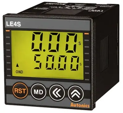
Transparent Guide LCD Digital Timers
The Transparent Guide LCD Digital Timers are electronic timers that can be used in various industrial applications. They have a transparent front panel that allows users to see the display clearly. The timers have a fail-safe device that can be installed when using the unit with machinery that may cause serious injury or substantial economic loss, such as nuclear power control, medical equipment, ships, vehicles, railways, aircraft, combustion apparatus, safety equipment, crime/disaster prevention devices, etc.
The unit has a compact design and can be installed on a device panel. It is important to follow the instructions provided in the manual while installing and using the unit to prevent any damage or injury. Users are advised not to connect, repair or inspect the unit while connected to a power source. The unit should be installed in a place where there is no possibility of flammable/explosive/corrosive gas, high humidity, direct sunlight, radiant heat, vibration, impact or salinity.
Users should check the connections before wiring and use the unit within the rated specifications to prevent any damage or injury. The unit cannot be disassembled or modified. Users should use a dry cloth to clean the unit and avoid using water or organic solvent. Keeping the product away from metal chip, dust, and wire residue is also essential to prevent any damage or fire.
Product Usage Instructions
The Transparent Guide LCD Digital Timers have different functions that users can use as per their requirements. The following are the product usage instructions:
- Install the unit on a device panel and make sure to use a fail-safe device while using it with machinery that may cause serious injury or substantial economic loss.
- Check the connections before wiring and use AWG 20 (0.50 mm2) cable or over, and tighten the terminal screw with a tightening torque of 0.74 to 0.90 N m.
- Use the unit within the rated specifications and do not disassemble or modify the unit.
- Use a dry cloth to clean the unit, and keep the product away from metal chip, dust, and wire residue.
- The unit has different keys that are used for different functions. The [RST] key is used to initialize the progressing time and output return. The [MD] key is used to enter RUN mode, and the [] key is used to shift to the next parameter in parameter setting.
- Users can use the UP / DOWN keys to select the time unit or mode of time progressing, and use the [] key to move the digit when changing the setting value.
- The unit also has a key lock function that shows the key lock status.
Thank you for choosing our Autonics product.
Read and understand the instruction manual and manual thoroughly before using the product.
For your safety, read and follow the below safety considerations before using. For your safety, read and follow the considerations written in the instruction manual, other manuals and Autonics website.
- Keep this instruction manual in a place where you can find easily.
- The specifications, dimensions, etc. are subject to change without notice for product improvement. Some models may be discontinued without notice.
- Follow Autonics website for the latest information.
Safety Considerations
- Observe all ‘Safety Considerations’ for safe and proper operation to avoid hazards.
- warning: symbol indicates caution due to special circumstances in which hazards may occur.
Warning: Failure to follow instructions may result in serious injury or death.
- Fail-safe device must be installed when using the unit with machinery that may cause serious injury or substantial economic loss. (e.g. nuclear power control, medical equipment, ships, vehicles, railways, aircraft, combustion apparatus, safety equipment, crime/disaster prevention devices, etc.) Failure to follow this instruction may result in personal injury, economic loss or fire.
- Do not use the unit in the place where flammable/explosive/corrosive gas, high humidity, direct sunlight, radiant heat, vibration, impact or salinity may be present.
Failure to follow this instruction may result in explosion or fire. - Install on a device panel to use.
Failure to follow this instruction may result in fire or electric shock. - Do not connect, repair, or inspect the unit while connected to a power source.
Failure to follow this instruction may result in fire or electric shock. - Check ‘Connections’ before wiring.
Failure to follow this instruction may result in fire. - Do not disassemble or modify the unit.
Failure to follow this instruction may result in fire or electric shock.
Caution: Failure to follow instructions may result in injury or product damage.
- When connecting the power/sensor input and relay output, use AWG 20 (0.50 mm2) cable or over, and tighten the terminal screw with a tightening torque of 0.74 to 0.90 N m.
Failure to follow this instruction may result in malfunction due to contact failure. - Use the unit within the rated specifications.
Failure to follow this instruction may result in fire or product damage. - Use a dry cloth to clean the unit, and do not use water or organic solvent. Failure to follow this instruction may result in fire or electric shock.
- Keep the product away from metal chip, dust, and wire residue which flow into the unit.
Failure to follow this instruction may result in fire or product damage.
Cautions during Use
- Follow instructions in ‘Cautions during Use’. Otherwise, it may cause unexpected accidents.
- When supplying or turning off the power, use a switch or etc. to avoid chattering.
- Install a power switch or circuit breaker in the easily accessible place for supplying or disconnecting the power..
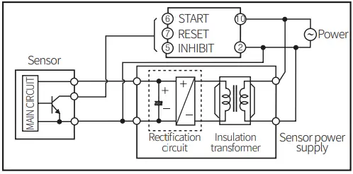
- In order to block peripheral current, use isolation transformer which of secondary part is not grounded to supply power to the external input device

- Do not connect two or more timers with only one input contact or transistor simultaneously.
- Keep away from high voltage lines or power lines to prevent inductive noise. In case installing power line and input signal line closely, use line filter or varistor at power line and shielded wire at input signal line.
- Do not use near the equipment which generates strong magnetic force or high frequency noise.
- This unit may be used in the following environments.
- Indoors (in the environment condition rated in ‘Specifications’)
- Altitude max. 2,000 m
- Pollution degree 2
- Installation category II
Ordering Information
This is only for reference, the actual product does not support all combinations. For selecting the specified model, follow the Autonics website.

Output
- No mark: Time limit 1c
- A: Time limit 2c, Time limit 1c + Instantaneous 1c
Product Components
- Product (+ bracket)
- Instruction manual
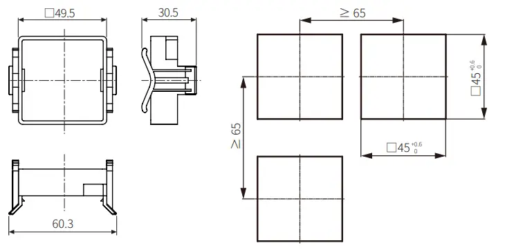
Dimensions
Unit: mm, For the detailed drawings, follow the Autonics website.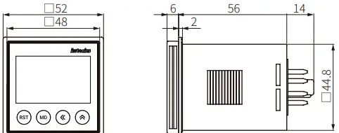
- Bracket
- Panel cut-out

Unit Descriptions
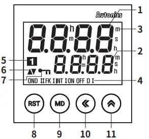
| No. | Name | Function |
| 1 | Time progressing display part | Shows progressing time |
| 2 | Time setting display part | Shows the setting time |
| 3 | Time unit | Shows time unit (h: hour / m: min / s: sec) Flashing: time progressing |
| 4 | Operation mode | Shows current output operation mode • INTG: no mark |
| 5 | Output contact | Shows the status of current output contact |
| 6 | UP / DOWN | Shows UP / DOWN mode of time progressing |
| 7 | Key lock | Shows key lock status |
| 8 | [RST] key | Initializes progressing time and output return |
| 9 | [MD] key | Enter RUN mode ↔ Parameter setting Shift to next parameter in parameter setting |
| 10 | [◀] key | Enter RUN mode ↔ setting time change mode Move the digit when changing the setting value. |
| 11 | [▲] key | Change the parameter setting value |
Mode Setting
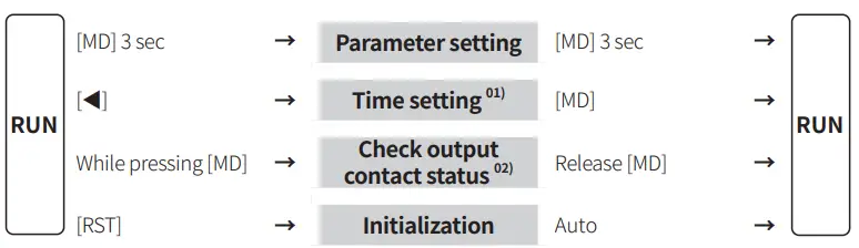
- If no key is pressed over 60 sec, returning to RUN mode and not storing the setting value.
- Only for the LE4SA model
Output Operation Mode
For the detailed timing chart for operation output mode, refer to the manual. The output operation mode differs depending on each model.
| Group | Output operation mode | LE4S | LE4SA | Time setting | |
|
Group 1 | OND | ON Delay |
○ | ○ |
Time |
| OND.1 | ON Delay 1 | – | |||
| OND.2 | ON Delay 2 | ○ | |||
| INT | Interval | ||||
| INT.1 | Interval 1 | – | |||
| OFD | OFF Delay | ||||
| INTG | Integration time | ||||
|
Group 2 | FLK | Flicker |
○ | ○ | tOFF, tON |
| FLK.1 | Flicker 1 | ||||
| NFD | ON – OFF Delay | – | OnD, OFfD | ||
| NFD.1 | ON – OFF Delay 1 | ||||
| Group 3 | S-D | Star – Delta | – | ○ | T-1, T-2 |
| TWN | Twin | ||||
| TWN.1 | Twin 1 | ||||
Parameter Setting
- Some parameters are activated / deactivated depending on the model or setting of other parameters. Refer to the description of each parameter.
- In the parameter setting, the time and output control continue.
- If the settings are changed, all outputs to be OFF and reset the current values when returning to RUN mode.
- [MD] key: saves current setting value and moves to the next parameter.
| Parameter | Display | Defaults | Setting range | Model | Display condition |
| Output 1-1 operation mode | OUtM | OND | • Refer to the output operation mode. |
Comm. | – |
| 1-2 Time range | tRNG | 9(99 | • Refer to the table below. | 1-1. Output operation mode: Group 1 | |
| One-shot 1-3 output time | OUTt | 0)50 | 0.01 to 99.99 sec | 1-1. Output operation mode: OND.2 | |
| 1-4 T.off time range | OfRG | 9(99 |
• Refer to the table below. | 1-1. Output operation mode: Group 2 | |
| 1-5 T.on time range | OnRG | 9(99 | |||
| 1-6 T1 time range | T!RG | 9(99 | [LE4SA] | 1-1. Output operation mode: Group 3 | |
| 1-7 T2 time range | T@RG | 9(99 | [LE4SA] | ||
| 1-8 Time UP / DOWN | U-D | UP | UP: 0 → setting time DN: setting time → 0 | Comm. | – |
| Width of 1-9 min. input signal | InT | 20 | 1, 20 ms • Set the min. width of RESET, START, INHIBIT input signals | [LE4S] | – |
| 1-10 Output contact 01) | CONT | 1c1C | 1C.1C: Time limit 1c + Instantaneous 1c 2C: Time limit 2c | [LE4SA] | – |
| 1-11 Backlight | BLU | ON | ON, OFF | Comm. | – |
|
1-12 Key lock |
LOCK | lOFF | L.OFF: release key lock LOC.1: lock [RST] key LOC.2: lock [◀], [▲] key LOC.3: lock [RST], [◀], [▲] key | [LE4S] |
– |
| LOc1 | [LE4SA] |
The output operation mode of group 3: 2C fixed
Table
| Unit | SEC | SEC | SEC | SEC | M S | M | M |
| Display | 9.999 | 99.99 | 999.9 | 9999 | 99m59s | 999.9m | 9999m |
| Range | 0.001s to 9.999s | 0.01s to 99.99s | 0.1s to 999.9s | 1s to 9999s | 0m1s to 99m99s | 0.1m to 999.9m | 1m to 9999m |
| Unit | H M | H | H | H |
| Display | 99h59m | 99.99h | 999.9h | 9999h |
| Range | 0h1m to 99h59m | 0.01h to 99.99h | 0.1h to 999.9h | 1h to 9999h |
Connections
Caution
- Refer to the ‘specifications’ for checking the power supply and control output.
- The LE4S model: Be sure to use terminal No. 2 as the common terminal to connect terminals No. 1, 3, and 4.
Failure to follow this instruction may result in product malfunction.
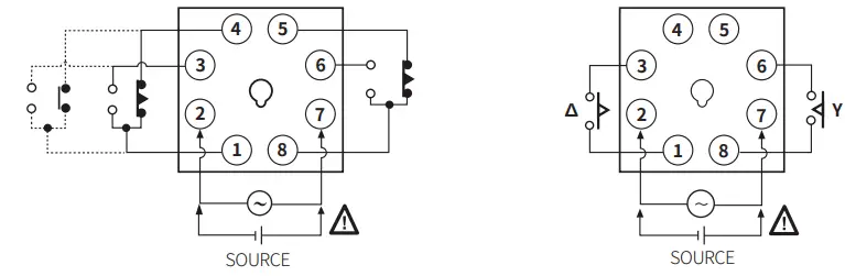
LE4S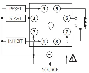 LE4SA
LE4SA
- Output operation mode
OND / OND.2 / FLK / FLK1 / INT / TWN / TWN.1 (TWN, TWN.1 mode: time limit 2c fixed) - Output operation mode: Y -∆ (Time limit 2c fixed)
- Use the A contact.

Specifications
| Model | LE4S | LE4SA | |
| Function | MULTI-time, MULTI operation | ||
| Display method | LCD (Backlight) | ||
| Return time | ≤ 100 ms | ||
| Time operation | Signal ON Start | Power ON Start | |
| Input signal | START, INHIBIT, RESET | ||
| Min. signal width | ≈ 1, 20 ms | – | |
| No-voltage input | Short-circuit impedance: ≤ 1 kΩ Short-circuit residual voltage : ≤ 0.5 VDC Open-circuit impedance: ≥ 100 kΩ | – | |
| Control output | Relay | ||
| Contact type | Time limit SPDT (1c) | Time limit DPDT (2c), Time limit SPDT (1c) + Instantaneous SPDT (1c) (depends on operation mode) | |
| Contact capacity | 250 VAC 5 A, 30 VDC 5 A resistive load | 250 VAC 3 A, 30 VDC 3 A resistive load | |
|
Error | Repeat | Power ON Start : ≤ ± 0.01% ± 0.05 sec Signal ON Start : ≤ ± 0.005% ±0.03 sec |
≤ ± 0.01% ± 0.05 sec |
| SET | |||
| Voltage | |||
| Temp. | |||
| Approval | |||
| Unit weight | ≈ 98 g | ||
| Model | LE4S | LE4SA |
| Power supply | 24 – 240 VAC ± 10% 50 / 60 Hz, 24 – 240 VDC ± 10% | |
| Power consumption | AC: ≤ 4.5 VA, DC: ≤ 2 W | AC: ≤ 4 VA, DC: ≤ 1.6 W |
| Insulation resistive | 100 MΩ (500 VDC megger) | |
| Dielectric strength | 2000 VAC 50 / 60 Hz for 1 min | |
| Noise immunity | ± 2 kV square-wave noise by noise simulator (pulse width 1 ㎲) | |
| Vibration | 0.75 mm double amplitude at frequency of 10 to 55 Hz (for 1 min) in each X, Y, Z direction for 1 hour | |
| Vibration (malfunction) | 0.5 mm double amplitude at frequency of 10 to 55 Hz (for 1 min) in each X, Y, Z direction for 10 min | |
| Shock | 300 m/s2 (≈ 30 G) in each X, Y, Z direction for 3 times | |
| Shock (malfunction) | 100 m/s2 (≈ 10 G) In each X, Y, Z direction for 3 times | |
| Relay life cycle | Mechanical: ≥ 10,000,000 operations Electrical: ≥ 100,000 operations | |
| Ambient temperature | -10 to 55 ℃, storage: -25 to 65 ℃ (no freezing or condensation) | |
| Ambient humidity | 35 to 85 %RH, storage: 35 to 85 %RH (no freezing or condensation) | |
18, Bansong-ro 513Beon-gil, Haeundae-gu, Busan, Republic of Korea, 48002 www.autonics.com | +82-2-2048-1577 | [email protected]


