![]()
TA-DEC Dual Extrusion Cell
Instruction Manual
TA-DEC Dual Extrusion Cell
Installation Instructions for Texture Accessory Part Number TA-DEC
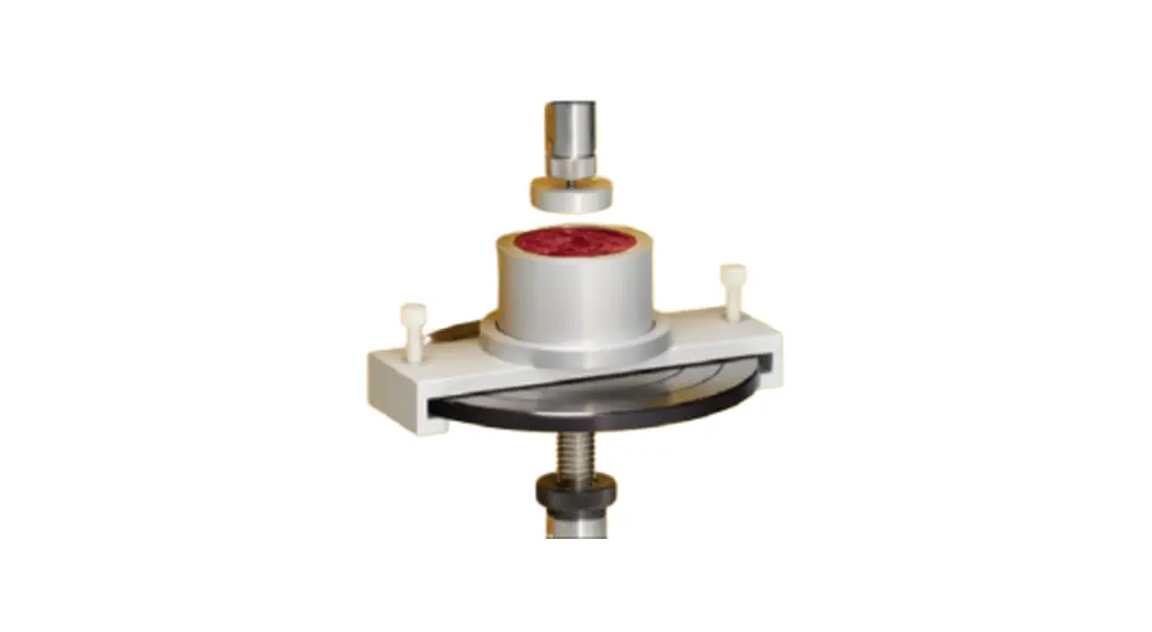
TA-DEC Dual Extrusion Cell Fixture The Dual Extrusion Cell Fixture is used to evaluate flow behavior of fluids and soft solids materials in an extrusion process. The sample chamber is fitted with a disc in the bottom that has a hole of a known diameter. Sample material is placed into the extrusion cell. A probe shaped like a plunger is attached to the CT3 Texture Analyzer. The choice of the probe diameter depends on the nature of the material being tested. Lower viscosity materials will be tested using a probe with a diameter that is almost equal to the chamber diameter. Higher viscosity materials will be tested with probes of smaller diameter.
The TA-DEC Fixture consists of a kit that includes:
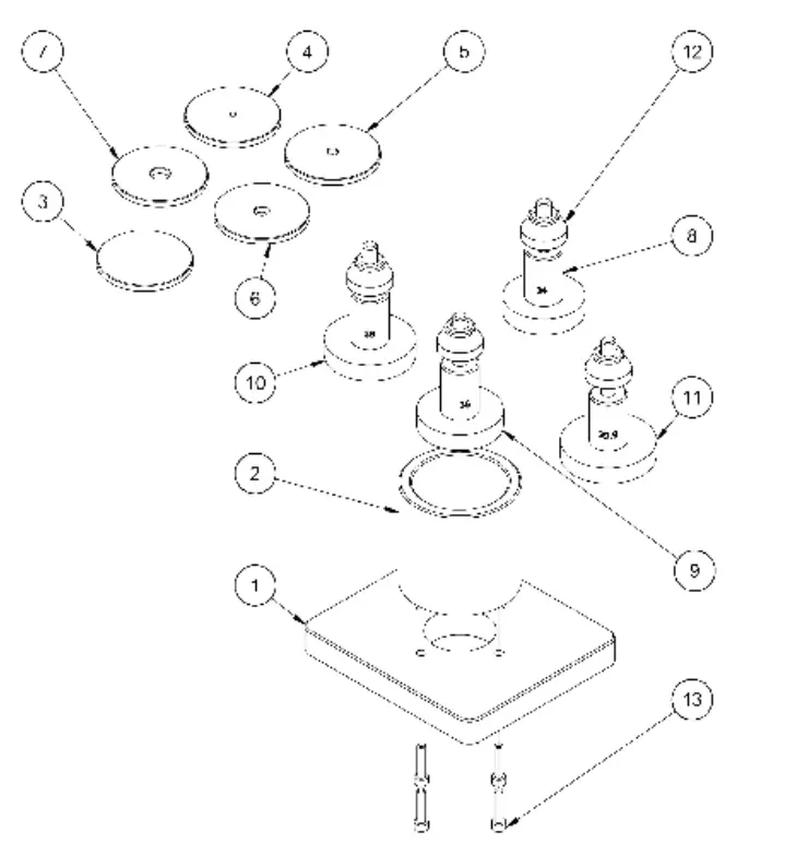
| ITEM | PART NUMBER | Paris Lim DESCRIPTION | QTY |
| 1 | TA-DEC-1 | BASE PLATE,DUAL EXTRUSION CELL | 1 |
| 2 | TA-DFC-Y | SAMPI F CONTAINFR | 1 |
| 3 | TA-DEC-3 | BASE DISK,BLANK | 1 |
| 4 | TA-DEC-4 | BASE DISK 2mm APERTURE | 1 |
| 5 | TA-DEC-5 | BASE DISK,4mm APERTURE | 1 |
| 6 | TA-DEC-6 | BASE DISK,6mm APERTURE | 1 |
| 7 | TA-DEC-7 | BASE DISK,6mm APERTURE | 1 |
| 8 | TA-DEC-8 | COMPRESSION DISC ,34m m | 1 |
| 9 | TA-DEC-9 | COMPRESSION DI SC ,36m m | 1 |
| 10 | TA-DEC-10 | COMPRESSION DISC ,30enm | 1 |
| 11 | TA-DEC-11 | COMPRESSION DISC ,39.9mm | 1 |
| 12 | TA-RT-3 | THUMB NUT | 4 |
| 11 | 505063220E140 | SCREW 6-32X5/8 SOC GAP HD 18-BSS | 4 |
Extrusion Cell (sample container with base plate)
- (4) probes with different diameters (compression discs)
- (5) discs with apertures (holes) of different diameters, except for one that is solid, no holes
See the diagram for part numbers, descriptions and dimensions.
The extrusion cell with the base plate fits onto the Fixture Base Table (TA-BT-KIT), which is purchased separately from the TA-DEC kit. The user chooses a disc for the test and places it in the bottom of the extrusion cell. Sample material is put into the extrusion cell. The user chooses a probe (compression disc) and attaches it to the CT3. To run the test, the user chooses a speed and distance of penetration into the extrusion cell for the probe. Experiment with different speeds and penetration distances to observe flow behavior of the material through the aperture in the disc at the bottom of the extrusion cell.
Select an appropriate container to place under the Fixture Base Table to catch the sample material that flows out of the extrusion cell.
When running a test with the solid disc in the extrusion cell, it is possible to reserve the direction of the probe after the compression stroke. As the probe returns to the top of the extrusion cell, the force that is measured gives an indication of the sample material’s adhesive property.
11 Commerce Boulevard, Middleboro, MA 02346 USATel: 800-628-8139 or 508-946-6200 · Fax: 508-946-6262
Email: [email protected]
www.brookfieldengineering.com
![]() Part No. M15-TADEC
Part No. M15-TADEC


