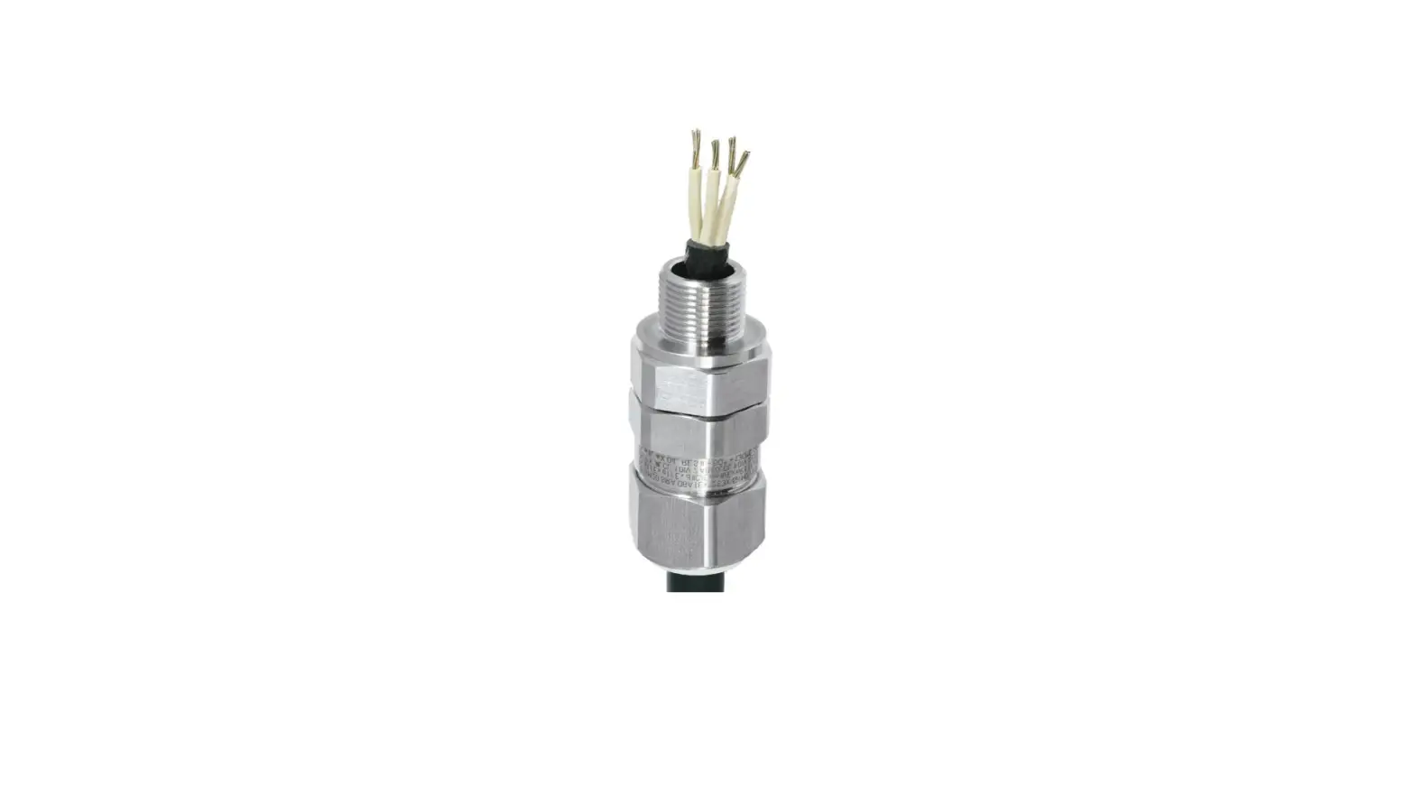
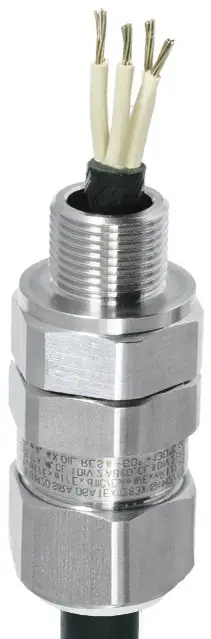
STAHL CMP-50TE1FU Cable Gland
PRODUCT INFORMATION
The CMP-50TE1FU cable gland is a metal Ex d and Ex e cable entry suitable for all types of armoured cables, including SWA, braid- and tape-type steel and aluminium armouring. It features a multi-functional holder for the armouring and various seals, and is designed to prevent cold flow. The product is EMC-tested and offersincreased safety with its auxiliary functions and sequential, three-stage installation. It is explosion proof and can be used in various application ranges (zones) including Ex e & Ex d & Ex nR & Ex ta 1 2 20 21 22 IECEx CML 18.0183X Ex db IIC Gb IECEx CML 18.0183X Ex ta IIIC Da IECEx SIM 14.0007 X Ex db I Mb Exeb I Mb IECEx CML 18.0183X Ex nR IIC Gc CML 18ATEX1326X E II 2 G Ex db IIC Gb CML 18ATEX1326X E II 1 D Ex ta IIIC Da CML 18ATEX1326X E I M2 Ex db I Mb E I M2 Ex eb I Mb CML 18ATEX4318X E II 3 G Ex nR IIC Gc.
- Ex d and Ex e cable entry for cables with SWA, braid- and tape- type steel and aluminium armouring
- Designed to prevent cold flow
- Compensating displacement seal (CDS), flood seal with integral protection, controlled outer load retention seal
- Worldwide certification in accordance with IECEx, ATEX and cCSAus, EMC- tested
INTRODUCTION
PRODUCT USAGE INSTRUCTION
- Ensure that the cable gland is suitable for the type of armoured cable being used.
- Insert the cable through the cable gland and into the equipment.
- Attach the armouring to the multi-functional holder.
- Place the seals onto the holder to prevent cold flow.
- Install the cable gland in three stages, following the sequential installation process to ensure increased safety.
- Refer to the manufacturer’s homepage to download product certification and certificates.
Note: The product dimensions, weights, and designs are subject to change without notice. The illustrations provided are not binding.
Technical Data
Explosion Protection
| Ex version | Ex e & Ex d & Ex nR & Ex ta |
| Application range (zones) | 1 2 20 21 22 |
| IECEx gas certificate | IECEx CML 18.0183X |
| IECEx gas explosion protection | Ex db IIC Gb |
| IECEx dust certificate | IECEx CML 18.0183X |
| IECEx dust explosion protection | Ex ta IIIC Da |
| IECEX firedamp certificate | IECEx SIM 14.0007 X |
| IECEx firedamp protection | Ex db I Mb |
| IECEx firedamp protection 2 | Ex eb I Mb |
| IECEx restricted breathing certificate | IECEx CML 18.0183X |
| IECEx restricted breathing | Ex nR IIC Gc |
| ATEX gas certificate | CML 18ATEX1326X |
| ATEX gas explosion protection | E II 2 G Ex db IIC Gb |
| ATEX dust certificate | CML 18ATEX1326X |
| ATEX dust explosion protection | E II 1 D Ex ta IIIC Da |
| ATEX firedamp certificate | CML 18ATEX1326X |
| ATEX firedamp protection | E I M2 Ex db I Mb |
| ATEX firedamp protection 2 | E I M2 Ex eb I Mb |
| ATEX restricted breathing certificate | CML 18ATEX4318X |
| ATEX restricted breathing | E II 3 G Ex nR IIC Gc |
| Notes | The product certification and certificates can be downloaded from the manufacturer’s homepage |
Ambient Conditions
| Ambient temperature | -60 °C … +130 °C |
Mechanical Data
| Version | 50 |
| Strain relief | No |
| Degree of protection (IP) | IP66 |
| Degree of protection note | IP67 and IP68 mounting in accordance with the specifications of the manufacturer, CMP |
| Sealing material | SOLO LSF |
| Sealing ring material | Viton |
| Material | Stainless steel |
| Silicone-free | Yes |
| Clamping range | 40.4 – 53 mm |
| Armouring type | All armouring |
| Armouring type 2 | Without lead sheath |
| Armouring type 3 | With double seal |
| Clamping range | 40.4 … 53 mm |
| Construction type | BS 6121, IEC/EN 62444 |
| Width across corners | 77.1 mm |
| Width across flats | 70.1 mm |
| Thread size | NPT2 |
| Thread length | 26.9 mm |
| Thread pitch | 11,5 TPI |
| Thread standard | NPT |
| Gland size | 50 |
| Grooved cone | 0.6 … 1.6 mm |
| Stepped cone | 2 … 2.5 mm |
| Inner sheath | 35.6 … 44 mm |
| Outer sheath | 40.4 … 53 mm |
| Protrusion length | 91.2 mm |
| Impact strength | 20 J |
| PVC boot | PVC21 |
| Lot size | 1 |
| Weight | 1.37 kg |
| Weight | 3.02 lb |
Dimension
Dimensional Drawings (All Dimensions in mm [inches]) – Subject to Alterations
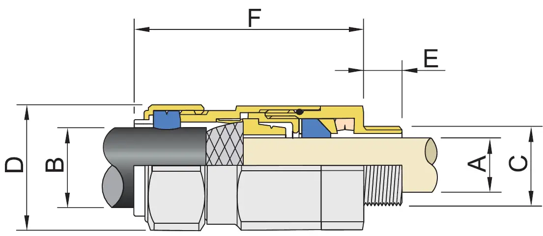
- A = Inner sheath
- B = Outer sheath
- C = Thread size
- D = Width across corners
- D = Width across flats
- E = Thread length
- F = Protrusion length
We reserve the right to make alterations to the technical data, dimensions, weights, designs and products available without notice. The illustrations cannot be considered binding.
R. STAHL Schaltgeräte GmbH | Am Bahnhof 30 | 74638 WALDENBURG
Tel. +49 7942 943 1700
+49 7942 943 1777
Email: [email protected]
r-stahl.com


