Schneider Electric iEM2250 Single Phase Multi-functional Energy Meter
Legal Information
The Schneider Electric brand and any trademarks of Schneider Electric SE and its subsidiaries referred to in this guide are the property of Schneider Electric SE or its subsidiaries. All other brands may be trademarks of their respective owners.
This guide and its content are protected under applicable copyright laws and furnished for informational use only. No part of this guide may be reproduced or transmitted in any form or by any means (electronic, mechanical, photocopying, recording, or otherwise), for any purpose, without the prior written permission of Schneider Electric.
Schneider Electric does not grant any right or license for commercial use of the guide or its content, except for a non-exclusive and personal license to consult it on an “as is” basis. Schneider Electric products and equipment should be installed, operated, serviced, and maintained only by qualified personnel.
As standards, specifications, and designs change from time to time, the information contained in this guide may be subject to change without notice.
To the extent permitted by applicable law, no responsibility or liability is assumed by Schneider Electric and its subsidiaries for any errors or omissions in the informational content of this material or consequences arising out of or resulting from the use of the information contained herein.
Safety information
Important information
Read these instructions carefully and look at the equipment to become familiar with the device before trying to install, operate, service, or maintain it. The following special messages may appear throughout this manual or on the
equipment to warn of potential hazards or to call attention to information that larifies or simplifies a procedure.
The addition of either symbol to a “Danger” or “Warning” safety label indicates that an electrical hazard exists which will result in personal injury if the instructions are not followed.
This is the safety alert symbol. It is used to alert you to potential personal injury hazards. Obey all safety messages that accompany this symbol to avoid possible injury or death.
DANGER indicates a hazardous situation which, if not avoided, will result in death or serious injury. Failure to follow these instructions will result in death or serious injury.
WARNING indicates a hazardous situation which, if not avoided, could result in death or serious injury.
CAUTION indicates a hazardous situation which, if not avoided, could result in minor or moderate injury.
NOTICE is used to address practices not related to physical injury.
Please note
Electrical equipment should be installed, operated, serviced and maintained only by qualified personnel. No responsibility is assumed by Schneider Electric for any consequences arising out of the use of this material. A qualified person is one who has skills and knowledge related to the construction, installation, and operation of electrical equipment and has received safety training to recognize and avoid the hazards involved.
About this manual
This manual discusses features of the iEM2250 single-phase multi-functional energy meter and provides installation and configuration instructions.
This manual assumes you have an understanding of single-phase multi-functional energy meter and are familiar with the equipment and power system in which your meter is installed.
This manual does not provide configuration information for advanced features where an expert user would perform advanced configuration. It also does not include instructions on how to incorporate meter data or perform meter
configuration using energy management systems or software, other than RS-485
Schneider Electric protocol tool.
The most up-to-date documentation about your device is available for download from www.se.com
Scan the book QR code below to access documentation related to the iEM2250 meter. Related documents
| Document | Number |
| iEM2250 installation sheet | PHA6516700 |
Safety precautions
Installation, wiring, testing and service must be performed in accordance with all local and national electrical codes.
DANGER
HAZARD OF ELECTRIC SHOCK, EXPLOSION, OR ARC FLASH
- Apply appropriate Personal Protective Equipment (PPE) and follow safe electrical work practices. See NFPA 70E, CSA Z462 or other local standards.
- Turn off all power supplying this device and the equipment in which it is installed before working on or in the equipment.
- Always use a properly rated voltage sensing device to confirm that all power is off.
- Do not exceed the maximum ratings of this device. Failure to follow these instructions will result in death or serious injury.
WARNING
UNINTENDED OPERATION
- Do not use this device for critical control or protection of persons, animals, property or equipment.
- Failure to follow these instructions can result in death, serious injury, or equipment damage.
WARNING
INACCURATE DATA RESULTS
- Do not rely solely on data displayed on the display or in software to determine if this device is functioning correctly or complying with all applicable standards.
- Do not use data displayed on the display or in software as a substitute for proper workplace practices or equipment maintenance.
Failure to follow these instructions can result in death, serious injury, or equipment damage.
Introduction
Meter overview
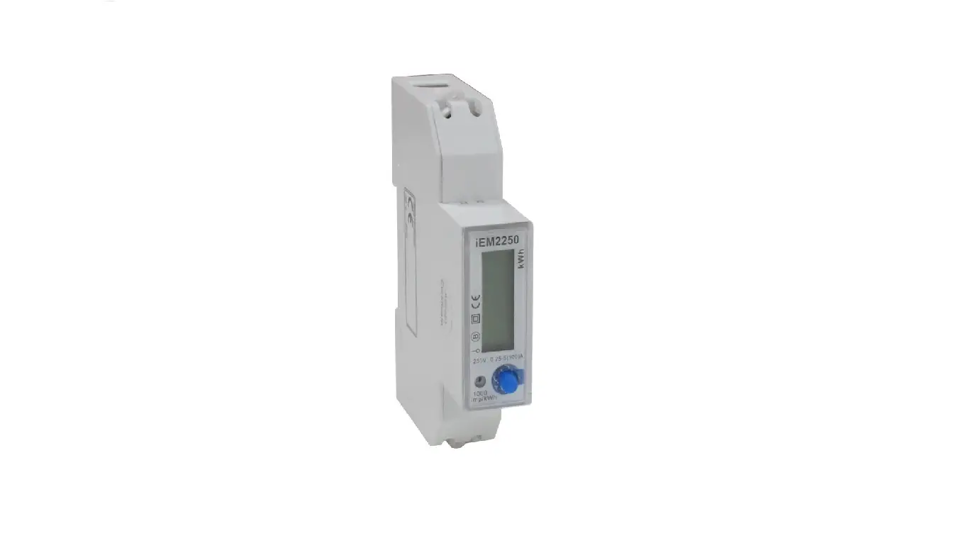
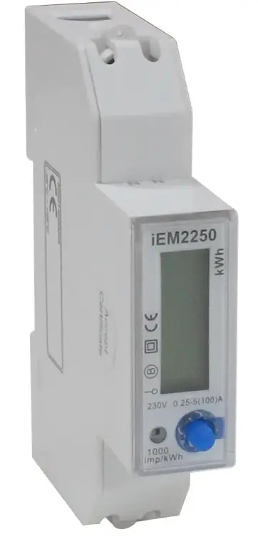
- The iEM2250 is a single phase multi-functional meter (100 A) for energy monitoring.
- The iEM2250 meter complies with Class B active energy accuracy as per EN50470-1/3 standard with high quality, reliability, and affordability in a compact and easy to install format.
Meter Features
- The key features of iEM2250 meter are listed below:
- Measurement of active and reactive energy, LCD display (current, voltage, power and energy measurements), Communication via RS-485 Schneider Electric protocol.
- For applications, feature details and complete specifications of the iEM2250 meter, see the iEM2250 technical datasheet at www.se.com.
Feature summary
| Parameter | iEM2250 |
| 4 quadrant energy measurements: • Active energy (kWh) • Reactive energy (kVArh) | √ |
| Power: • Active power (kW) • Apparent power (kVA) • Reactive power (kVAr) | √ |
| Current | √ |
| Voltage | √ |
| Power factor | √ |
| Communication | RS-485 Schneider Electric protocol |
| Class B as per EN 50470-1/3 | √ |
Hardware references
DIN mount energy meter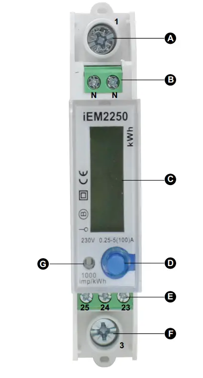
| A | Line-in (L-IN) (1) |
| B | Neutral (N) |
| C | LCD display |
| D | Button |
| E | RS-485 port (23, 24 and 25) |
| F | Line-out (L-OUT) (3) |
| G | Impulse indicator |
Supplemental information
- This document is intended to be used in conjunction with the installation sheet that ships in the box with the meter.
- See the meter’s installation sheet for information related to installation.
- See the product’s catalog pages at www.se.com for information about your meter and its options.
- You can download updated documentation from www.se.com or contact your local Schneider Electric representative for the latest information about your product.
Meter wiring
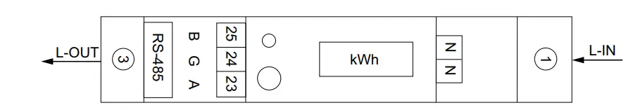
| 1 | Line-in (L-IN) |
| 3 | Line-out (L-OUT) |
| 23 | A+ |
| 24 | G |
| 25 | B- |
| N | Neutral |
NOTE: If the RS-485 communication converter does not have a G port, no need to connect. For Neutral wire, you can connect one N port.
Meter display
Display parameters
Two modes for data display:
- Auto scroll mode: Every 5 seconds the meter displays the next data page.
- Button mode: External button to check the data parameters.

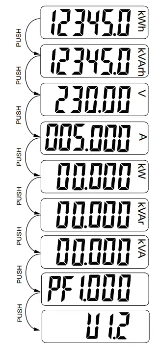
| LCD | Parameters | |
| 12345.0 | kWh | Active energy |
| 12345.0 | kVArh | Reactive energy |
| 230.00 | V | Voltage |
| 005.000 | A | Current |
| 00.000 | kW | Active power |
| 00.000 | kVAr | Reactive power |
| 00.000 | kVA | Apparent power |
| PF 1.000 | – | Power factor |
| U 1.2 | – | Firmware version |
Communication
Communication through protocol
The meter supports RS-485 Schneider Electric protocol. There are different software systems and methods you can use to access or display the meter data. This can range from using a simple protocol register interface to read stored values in the meter registers, to viewing intelligent information from the meter through an energy management system. The cable should be connected to terminals 23, 24 and 25. The default communication address of the meter is
Default protocol settings are as follows:
- Meter ID: 1
- Baud rate: 9600 bps
- Data bit: 8
- Parity: Even
- Stop bit: 1
The baud rate values can be changed to 4800, 2400 or 1200. The parity can be set to none or odd. Data bit and stop bit cannot be changed.
Register list column description
| Register Address | Address of register encoded in the protocol frame, in decimal (dec) |
| Action | R = Read only register W = Write only register R/W = Read Write register R/WC = Read register, write through Command register |
| Size | Data size in number of registers |
| Type | Data type |
| Units | Unit of the register value |
| Description | Information about the register and the range and values that apply |
The protocol register list data types are as follows:
| Type | Description | Range |
| UInt16 | 16 bits unsigned integer | 0 to 65535 |
| UInt32 | 32 bits unsigned integer | 0 to 4294967295 |
| Int64 | 64 bits signed integer | −9223372036854775808 to +9223372036854775807 |
| UTF8 | Alphanumeric 8 bit field | 0 to 3 bytes |
| Float32 | 32 bits floating point | ±1×1038 |
| 4Q FP PF | Four quadrant floating point power factor | -2 to +2 |
Register list system
| Address | Register | Action | Size | Type | Units | Description |
| 0x001E | 31 | R | 20 | UTF8 | – | Meter name |
| 0x0032 | 51 | R | 20 | UTF8 | – | Meter model |
| 0x0046 | 71 | R | 20 | UTF8 | – | Manufacturer |
| 0x005A | 91 | R | 1 | UInt16 | – | Meter code |
| 0x0082 | 131 | R/W | 2 | UInt32 | – | Serial number |
| 0x0088 | 137 | R | 5 | UTF8 | – | Hardware revision in x.x.x format (for example, 1.0.0) NOTE: The first number is the major version, the second number is the minor version, and the third number is normally not used. |
| 0x0665 | 1638 | R | 1 | UInt16 | – | Present firmware version |
| 0x0668 | 1641 | R | 5 | UTF8 | – | Checksum |
Meter setup and status
| Address | Register | Action | Size | Type | Units | Description |
| 0x07DE | 2015 | R | 1 | UInt16 | – | Number of phases (always 1) |
| 0x07DF | 2016 | R | 1 | UInt16 | – | Number of wires (always 2) |
| 0x07E0 | 2017 | R | 1 | UInt16 | – | Power system (always 0 = 1PH2W L-N) |
| 0x07E1 | 2018 | R | 1 | UInt16 | Hz | Nominal frequency (always 50 Hz) |
| 0x07E4 | 2021 | R | 2 | Float32 | A | Meter Amps (always 100 A) |
Current, voltage, power, power factor, and frequency
| Address | Register | Action | Size | Type | Units | Description |
| Current | ||||||
| 0x0BB8 | 3001 | R | 2 | Float32 | A | Current |
| Voltage | ||||||
| 0x0BD4 | 3029 | R | 2 | Float32 | V | Voltage |
| Power | ||||||
| 0x0BEE | 3055 | R | 2 | Float32 | kW | Active power |
| 0x0BFC | 3069 | R | 2 | Float32 | kVAr | Reactive power |
| 0x0C04 | 3077 | R | 2 | Float32 | kVA | Apparent power |
| Power factor | ||||||
| 0x0C0C | 3085 | R | 2 | 4Q_FP_ PF | – | Total power factor: • -2 < PF < -1 = Quad 2, active power negative, capacitive • -1 < PF < 0 = Quad 3, active power negative, inductive • 0 < PF < 1 = Quad 1, active power positive, inductive • 1 < PF < 2 = Quad 4, active power positive, capacitive |
| Frequency | ||||||
| 0x0C26 | 3111 | R | 2 | Float32 | Hz | Frequency • Range : 40 to 70 |
Energy
Energy values – 64-bit integer
| Address | Register | Action | Size | Type | Units | Description |
| 0x0C8C | 3213 | R | 4 | Int64 | Wh | Total active energy |
| 0x0C9C | 3229 | R | 4 | Int64 | VARh | Total reactive energy |
Energy values – 32-bit floating point
| Address | Register | Action | Size | Type | Units | Description |
| 0xB038 | 45113 | R | 2 | Float32 | Wh | Total active energy |
| 0xB03A | 45115 | R | 2 | Float32 | VARh | Total reactive energy |
Command interface
| Address | Register | Action | Size | Type | Units | Description |
| 0x1482 | 5251 | W | 1 | UInt16 | – | Requested command |
| 0x1483 | 5252 | W | 1 | UInt16 | – | Reserved for future use |
| 0x1484 – 0x14FE | 5253 – 5262 | W | 1 | UInt16 | – | Command parameter 001 to 010 |
| 0x14FF | 5376 | R | 1 | UInt16 | – | Command status |
| 0x1500 | 5377 | R | 1 | UInt16 | – | Command result |
Display
| Address | Register | Action | Size | Type | Units | Description |
| 0x17D4 | 6101 | R/WC | 1 | UInt16 | – | LCD cycle time |
Communication
| Address | Register | Action | Size | Type | Units | Description |
| 0x1965 | 6502 | R/WC | 1 | UInt16 | – | RS-485 communication port (M/S) address • 1 to 247 |
| 0x1966 | 6503 | R/WC | 1 | UInt16 | – | RS-485 communication port (M/S) baud rate: • 1 = 9600 • 2 = 4800 • 3 = 2400 • 4 = 1200 |
| 0x1967 | 6504 | R/WC | 1 | UInt16 | – | RS-485 communication port (M/S) parity: • 1 = Even • 2 = None • 3 = Odd |
Command list
LCD cycle time
| Command Number | Action (R/W) | Size | Type | Unit | Range | Description |
| 4001 | W | 1 | UInt16 | — | — | (Reserved) |
| W | 1 | UInt16 | — | 1 – 30 seconds | LCD cycle time |
Communication
| Command Number | Action (R/W) | Size | Type | Unit | Range | Description |
| W | 1 | UInt16 | — | — | (Reserved) | |
| W | 1 | UInt16 | — | — | (Reserved) | |
| W | 1 | UInt16 | — | — | (Reserved) | |
| W | 1 | UInt16 | — | 1 – 247 | Meter ID (Modbus) | |
| 1 – 4 | Baud Rate: | |||||
| 1 = 9600 | ||||||
| 5000 | W | 1 | UInt16 | — | 2 = 4800 | |
| 3 = 2400 | ||||||
| 4 = 1200 | ||||||
| 1 – 3 | Parity: | |||||
| W | 1 | UInt16 | — | 1 = Even 2 = None | ||
| 3 = Odd | ||||||
| W | 1 | UInt16 | — | — | (Reserved) |
Meter specifications
The specifications contained in this section are subject to change without notice. For installation and wiring information, refer to the meter installation sheet.
Mechanical characteristics
| Mounting position | Vertical |
| Display type | 6 digit LCD |
| Backlight | Blue |
| Keypad | 1 button |
| Front panel LED indicator | Impulse indication |
| Weight | ~ 0.1 kg |
| Dimensions W x H x D | 17.8 x 90 x 72 mm max |
Electrical characteristics
Measurement accuracy
| Active Energy | Class B as per EN 50470-1/3 standard |
Frequency
| Operational frequency | 50 Hz |
Voltage inputs
| Rated voltage | 230 V |
Current inputs
| Base current (Ib) | 5 A |
| Start current | 0.004Ib |
| Maximum current | 100 A |
Power consumption
| Internal power consumption | ≤8 VA, ≤0.4 W |
Pulse characteristics
| Impulse constant | 1000 imp/kWh |
| Pulse width | 90 ms |
Environmental characteristics
| Operating temperature | -25 °C to +55 °C (-13 °F to +131 °F) |
| Storage temperature | -25 °C to +80 °C (-13 °F to 176 °F) |
| Operating humidity | ≤75% (Non-condensing) |
| Storage humidity | ≤85% |
| Protection | IP51 front display |
| Location | For indoor use only Not suitable for wet locations Mechanical environmental class: M1 as per 2014/32/EU directive Electromagnetic environmental class: E2 as per 2014/32/EU directive |
RS-485 communications
| Protocol | RS-485 Schneider Electric |
| Baud rate | 1200, 2400, 4800, and 9600 (default) |
| Address range | 1 to 247 user-configurable |
Schneider Electric
35 rue Joseph Monier
92500 Rueil Malmaison
France
+ 33 (0) 1 41 29 70 00
www.se.com
As standards, specifications, and design change from time to time, please ask for confirmation of the information given in this publication.
© 2021 – Schneider Electric. All rights reserved.
PHA9460800-01


