![]() iEM3310 / iEM3335 / iEM3355 /
iEM3310 / iEM3335 / iEM3355 /
iEM3365 / iEM3375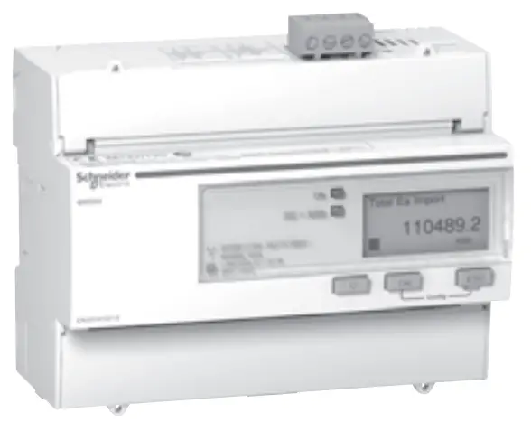
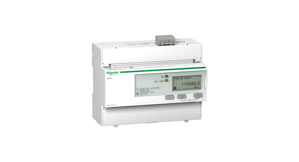
A9MEM3355 iEM3355 Energy Meter
| iEM3300 series 125 A watt-hour meter (MID) You can download user manuals and other documentation at www.schneider-electric.com. Type iEM3000 series in the search field. | Refer to the user manual when you see the icon above. |
MID compliance
| iEM3310 | |
| iEM3335 | |
| iEM3355 | |
| iEM3365 | |
| iEM3375 |
Complies with the European Measuring Instruments Directive (MID) 2004/22/ CE when installed in a suitable switchboard in accordance with the instructions in DOCA0038EN, available on our website. The CE declaration document is also available; search for ECDiEM3000.
Dimensions
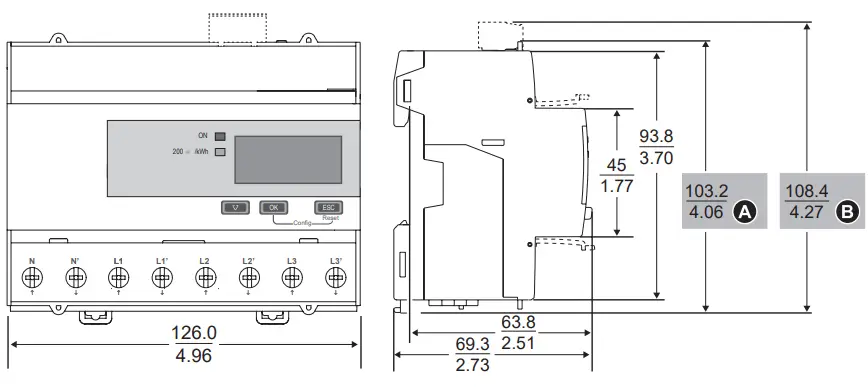
| iEM3310 | |
| iEM3335 | |
| iEM3355 | |
| iEM3365 | |
| iEM3375 |
Safety precautions
DANGER
HAZARD OF ELECTRIC SHOCK, EXPLOSION, OR ARC FLASH
- Apply appropriate personal protective equipment (PPE) and follow safe electrical work practices. See NFPA 70E in the USA or applicable local standards.
- Turn off all power supplying this device before working on it.
- Always use a properly rated voltage sensing device to confirm that all power is off.
- Do not exceed the device’s ratings for maximum limits.
- Do not use this device for critical control or protection applications where human or equipment safety relies on the operation of the control circuit.
- Do not allow the total additive current flowing through the device to exceed 125 A.
Failure to follow these instructions will result in death or serious injury.
- Turn off all power supplying this device before working on it.
- Always use a properly rated voltage sensing device to confirm that all power is off.
Overview
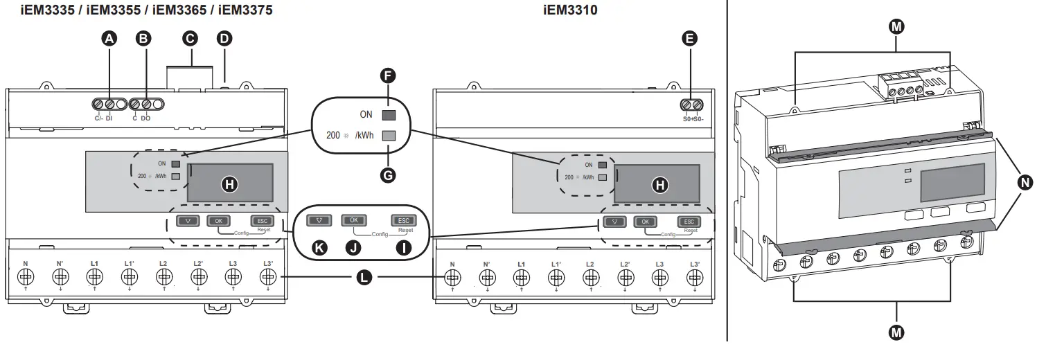
| A | Digital input |
| B | Digital output |
| C | Communications port (see section 11) |
| D | Communications LED (see section 11) |
| E | Pulse output (iEM3310 only) |
| F | Status LED: on / off / error |
| G | Energy pulse LED (200 flashes / kWh) |
| H | Display for measurement and configuration |
| I | Cancel |
| J | Confirm |
| K | Scroll |
| L | L1 – L3, N |
| M | Sealing points (4) |
| N | Sealable covers (2) |
Operation LEDs
F Status
G Energy pulse
![]()
| F | ||||||
| G | (1s) → | |||||
| Off | On. not counting | On. counting | Internal error, counting is stopped’ | Abnormal. counting continues’ | ‘See section 12 – Troubleshooting |
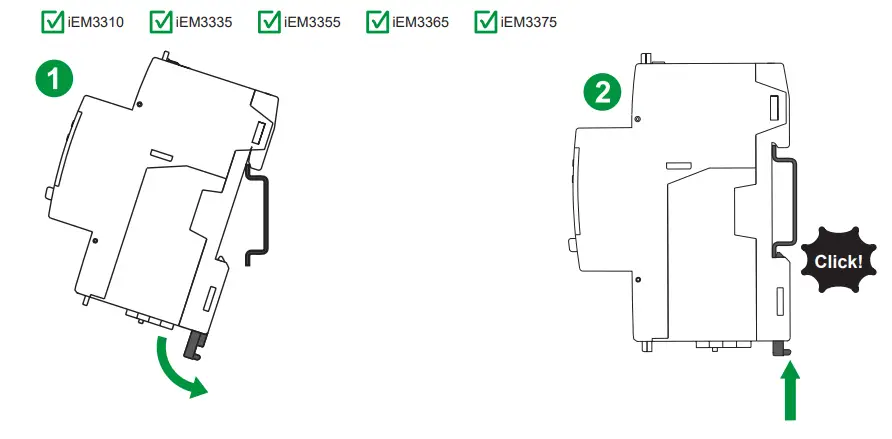
Installation
Wiring
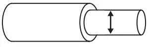 | |||
| DI, DO, C, C/- | 1.5 mm2/ 16 AWG | 0.5 Nm / 4.4 in lb | 6 mm / 0.23 in |
| L1 – L3, N | 50 mm2 / 1 AWG | 3.5 Nm / 30.9 in-lb | 13 mm / 0.5 in |
| SO+, SO- | 2.5 mm2/ 14 AWG | 0.5 Nm / 4.4 in lb | 7 mm / 0.28 in |
| RS-485, Lon, M-Bus | 2.5 mm2 / 14 AWG | 0.5 Nm / 4.4 in-lb | 7 mm / 0.28 in |
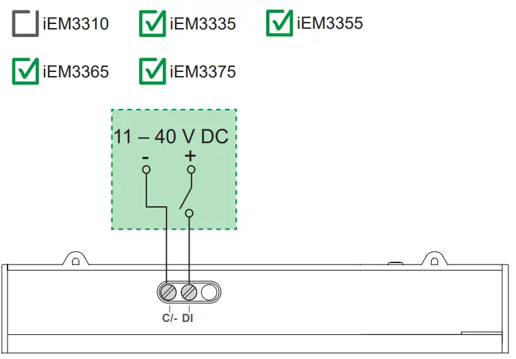
Digital input
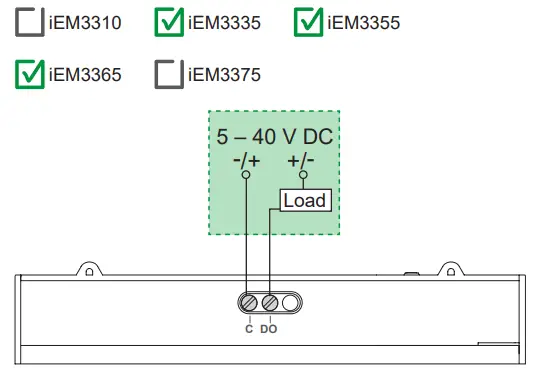
Digital output
Pulse output
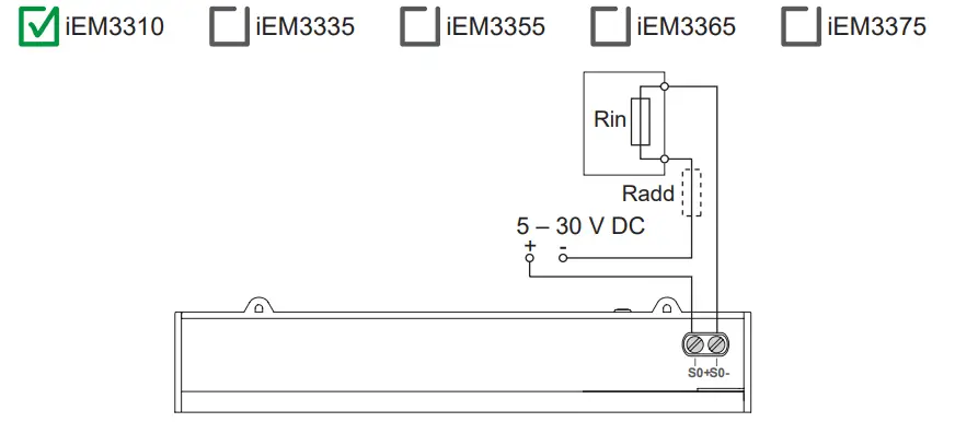
- The pulse output indicates the primary consumption with consideration of transformer ratios.
- It can be directly connected to a 24 V DC (< 30 V DC) input on a Zelio or Twido PLC.
- For other concentrators, if V DC / Rin > 15 mA, add a resistor Radd = (V DC / 0.01) – Rin Ω
Modbus / BACnet RS-485
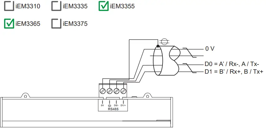
LonWorks / M-Bus
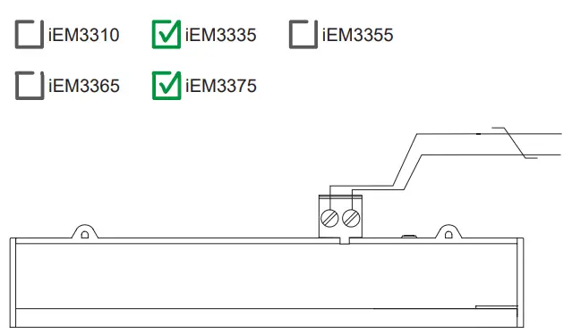
The Lon and M-Bus ports are polarity-independent.
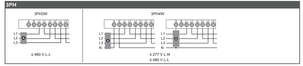
Power system wiring
F Fuses and disconnect switch Clearly label the device’s disconnect circuit mechanism and install it within easy reach of the operator.
Fuses / circuit breakers must be:
- installed in accordance with all local and national electrical codes and standards, and
- rated for the installation voltage, available fault current, and sized for connected loads.
Fuse for neutral is required if the source neutral is not grounded.
1PH
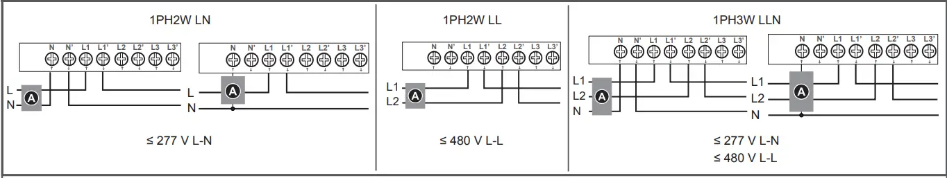
1PH multiple load with N
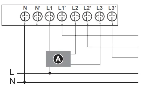
![]() DANGER
DANGER
HAZARD OF ELECTRIC SHOCK, EXPLOSION, OR ARC FLASH
Do not connect N’ to the load when setting the wiring type on the meter to 1PH4W Multi L-N.
Failure to follow these instructions will result in death or serious injury.
Display overview
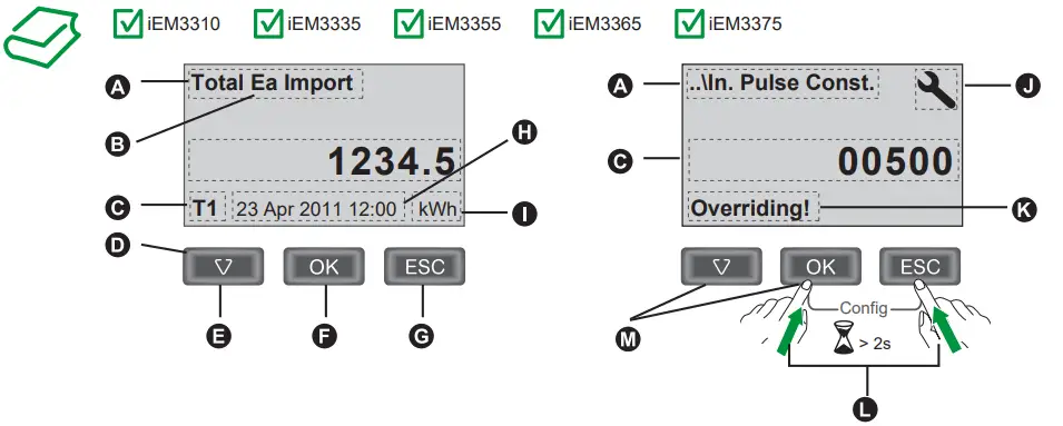
| A | Measurement / Parameter |
| B | Ea / Er = active / reactive energy |
| C | Value / Setting |
| D | Active tariff |
| E | Scroll through screens or a list of options |
| F | Confirm entry or access more screens |
| G | Cancel and go back to previous screen |
| H | Date and time |
| I | Units |
| J | Configuration mode icon |
| K | Indicates that the setting impacts Multi Tariffs |
| L | Press and hold OK + ESC to enter configuration mode |
| M | List setting: Press the down arrow to select an option from a list then press OK Numeric value: Press the down arrow to increment the selected digit then press OK to move to the next digit |
Initial clock setting
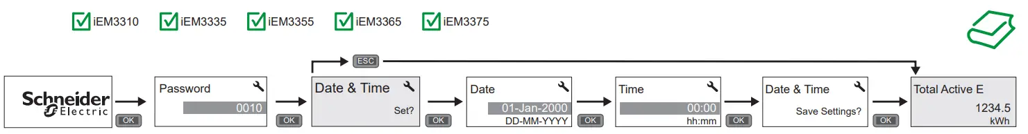
These instructions only apply on initial power up.
Basic configuration
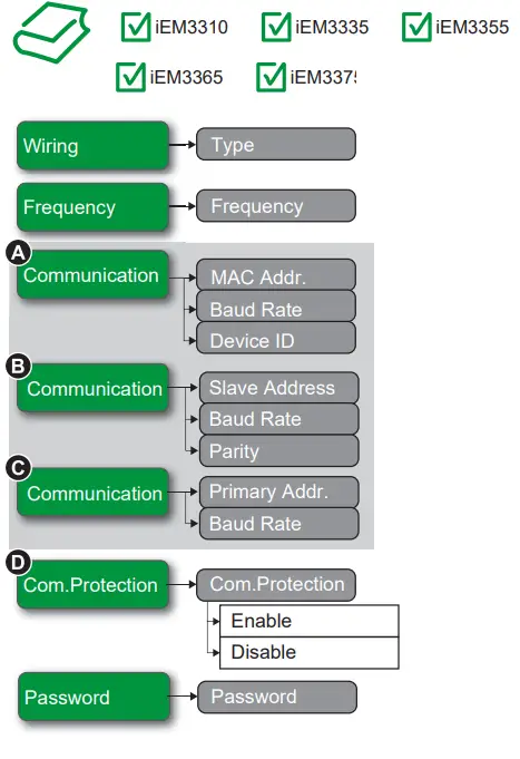
Enter configuration mode and configure basic metering, communications, and security settings (see section 7 for instructions)
A iEM3335
B iEM3355
C iEM3365
D iEM3335 / iEM3355 /
E iEM3365 / iEM3375
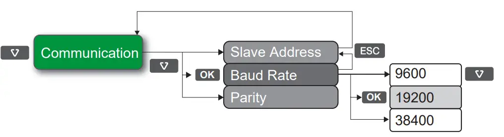
Example configuration
Verification
After performing basic configuration, navigate to the realtime data screens and verify that the readings are correct.
Communications
| Off: inactive | |
| Flashing: active | |
| See section 4 for the LED location |
Before you connect your meter to your network, configure the basic communications settings (see section 9).
LonWorks
| iEM3310 | |
| iEM3335 | |
| iEM3355 | |
| iEM3365 | |
| iEM3375 |
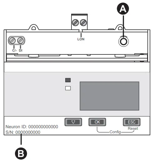
A LonWorks service pin
B NeuronID
See section 4 for the LED location.
Service – Red
| Off: Configured may be online or offline | |
| On: • Unconfigured – without an application, or • Defective external memory | |
| Flashing: Unconfigured – with an application |
Communication – Green
| Off: inactive | |
| Flashing: active |
Troubleshooting
| Code | Description | Possible solution |
| – | LCD display is not visible. | Check and adjust LCD contrast. |
| – | Push buttons do not function. | Restart the energy meter by powering off and powering on again. |
| 101 | Metering stops due to an EEPROM error. Press OK to display total energy consumption. | Enter configuration mode and implement Reset Config. |
| 102 | Metering stops due to a lack of a calibration table. Press OK to display total energy consumption. | Enter configuration mode and implement Reset Config. |
| 201 | Metering continues. Mismatch between frequency settings and frequency measurements. | Correct the frequency settings according to the nominal frequency of the power system. |
| 202 | Metering continues. Mismatch between wiring settings and wiring inputs. | Correct the wiring settings according to the wiring inputs. |
| 203 | Metering continues. Phase sequence reversed. | Check the wire connections and correct the wiring settings if needed. |
| 204 | Metering continues. Total active energy negative due to incorrect voltage and current conditions. | Check wire connections. |
| 205 | Metering continues. Date and Time have been reset due to a loss of power. | Set the Date and Time. |
| 206 | Metering continues. Pulse is missing due to overload on energy pulse output. | Check the energy pulse output settings. |
| 207 | Metering continues. Abnormal intemal clock function. | Restart the energy meter by powering off and powering on again then reset the date and time. |
Specifications
Power supply
- Wye: 100 – 277 V L-N, 173 – 480 V L-L ±20%
- Delta: 173 – 480 V L-L ±20%
- Frequency: 50 Hz / 60 Hz ±10%
- Maximum voltage: 332 V L-N or 575 V L-L
- Measurement category III
- Maximum current: 125 A
- Measured current: 1 A – 125 A
- Minimum wire temperature rating required: 105 °C (221 °F)
- Voltage impedance: 6 MΩ
- Current impedance: < 0.2 mΩ
- Burden: < 10 VA at 125 A
Digital input
- Type 1 (IEC61131-2)
- Off: 0 – 5 V DC
- On: 11 – 40 V DC
- Maximum input: 40 V DC, 4 mA
- Nominal: 24 V DC
Digital output
- Type: Form A
- 5 – 40 V DC, 50 mA maximum
Read these instructions carefully and look at the equipment to become familiar with the device before trying to install, operate, service or maintain it. The following special messages may appear throughout this bulletin or on the equipment to warn of potential hazards or to call attention to information that clarifies or simplifies a procedure.![]() The addition of either symbol to a “Danger” or “Warning” safety label indicates that an electrical hazard exists which will result in personal injury if the instructions are not followed.
The addition of either symbol to a “Danger” or “Warning” safety label indicates that an electrical hazard exists which will result in personal injury if the instructions are not followed.![]() This is the safety alert symbol. It is used to alert you to potential personal injury hazards. Obey all safety messages that follow this symbol to avoid possible injury or death.
This is the safety alert symbol. It is used to alert you to potential personal injury hazards. Obey all safety messages that follow this symbol to avoid possible injury or death. DANGER
DANGER indicates an imminently hazardous situation which, if not avoided, will result in death or serious injury.
Electrical equipment should be installed, operated, serviced and maintained only by qualified personnel. No responsibility is assumed by Schneider Electric for any consequences arising out of the use of this material. A qualified person is one who has skills and knowledge related to the construction, installation, and operation of electrical equipment and has received safety training to recognize and avoid the hazards involved.

HRB91202-02Schneider Electric 35, rue Joseph Monier
CS 30323
F – 92506 Rueil Malmaison Cedex
www.schneider-electric.com
HRB91202-02
© 2016 Schneider Electric. All rights reserved.
11/2016


 Aeoezw095c3a100 Manual")
 Aeoezw095c3a200 Manual")

 Aeoezw095c1a100 Manual")

 Aeoezw095c1a200 Manual")


 Aeoezw095c3a60 Manual")

 Aeoezw095c1a60 Manual")
