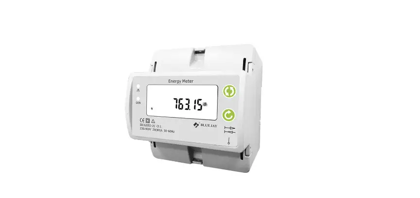
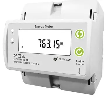
BLUE JAY 19D-24D Single Phase Energy Meter 
Product Information
The 19D-24D Single Phase Energy Meter is an intelligent device used in medium and low voltage systems (6-35KV and 0.4KV). It integrates data acquisition and control functions, has a single-phase AC power measurement and calculation, energy
accumulation, RS485 communication, and other functions. The maximum load can directly have connected to 80A current. It has a 4M width single phase din rail energy meter with built-in interfaces that provide pulse and RS485 Modbus RTU outputs. There is also an optional prepaid metered version and wireless communication version available.
Features
- All power parameter measurement
- Energy measurement and electrical fire monitor and control
- Transformers, generators, capacitors, and electric motors distributed detection
- Medium and low-pressure systems
- SCADA, EMS, DCS integrators
Technical Parameters
- Voltage Measurement & Display
- Current Overload Consumption Frequency Display
- Maximum Display Value AUX Power Output
- Digital Port Pulse Port Other Parameters
- Working Environment Storage Environment Voltage Tolerance Shock
Voltage Insulation
Product Usage Instructions
Before using the 19D-24D Single Phase Energy Meter, read the user manual carefully to fully understand the implications and the correct guidance of operations. Follow the instructions below to make better use of the product:
- Ensure that the power supply is within the provisions of the instrument before turning on the power supply.
- During installation, ensure that the current input terminal is non-open, and the voltage input terminals are non-short circuit.
- Do not impose communication terminal (RS232/RS485) on high pressure.
- Ensure that the instrument wiring is consistent with the internal system settings.
- When communicating with the PC, ensure that the instrument communication parameters are consistent with the PC.
Save this user manual for future reference.
Single Phase Energy Meter
Read me
When you use 19D-24D single phase energy meter, be sure to read this user manual carefully, and be able to fully understand the implications, the correct guidance of operations in accordance with user manual, which will help you make better use of 19D-24D single phase energy meter, and help to solve the various problems at the scene.
- Before the meter turning on the power supply, be sure that the power supply within the provisions of the instrument;
- When installation, the current input terminal must non-open, voltage input terminals must Non-short circuit;
- Communication terminal (RS232/RS485) is strictly prohibited to impose on high pressure;
- Be sure the instrument wiring consistent with the internal system settings;
- When communicating with the PC, instrument communication parameters must be consistent with the PC.
- Please read this user manual carefully
- Please save this document
Tel: +0086-023-67628702
www.cqbluejay.com
Add: 1802,Building 2,No.88,Jianxin East Road,Chongqing,400020,China
SUMMARIZE
Single-phase rail-type electric energy meter is an intelligent device used in medium and low voltage systems (6-35KV and 0.4KV). It integrates data acquisition and control functions, adopts segment code LCD screen, and has single-phase AC power measurement and calculation. Energy accumulation, RS485 communication and other functions. 19D-24D single phase energy meter is 4M width single phase din rail energy meter, maximum load can directly have connected to 80A current. Built-in interfaces provide pulse and RS485 Modbus RTU outputs. Optional prepaid metered version, wireless communication version.
FEATURES
- 10(80) A direct access, 0.04A start current
- Din-rail mounting 35mm, 4M width size
- Accuracy class 1.0
- Measures and display KWh Kvarh, KW, PF, HZ, V, A, etc.
- Provide energy import and export measurement (IMP & EXP)
- With 1* energy pulse output
- With 1* DO port
- With 1* RS485 port
- Optional multi-tariff record, max demand and other important parameters
- Optional prepaid recharged function (ID card)
- Optional built-in latching relay for remote control
- Optional internal wireless module for various communication
APPLICATIONS
- All power parameter measurement;
- Energy measurement and electrical fire monitor and control;
- Transformers, generators, capacitors and electric motors distributed detection;
- Medium and low pressure systems;
- SCADA, EMS, DCS integrators.
TECHNICAL PARAMETERS
Measurement & Display
- Voltage : Rated 230V RMS value, Accuracy 0.5%,
- Current : Rated 5A, Optional 1A, CT Connection, RMS value. Accuracy 0.2%;
- Overload : 1.2 times rated continuous; 10 seconds for 1 times the rated
- Consumption : <0.4VA(per phase)
- Frequency : 40-65Hz, Accuracy ±0.01Hz
- Display : LCD with white backlit
- Maximum display value : 9999999MkWh
- AUX Power : 90-240V AC, <2W/10VA
Output
Digital port : RS-485 MODBUS-RTU
Pulse port : 1600imp/kWh
Other parameters
- Working environment : -10~55°C Altitude ≤2000m, 0~93%RH, non-condensing, non-corrosive gas
- Storage environment : -30~70C
- Voltage tolerance : 2KV 1min
- Shock voltage : 6KV-1.2uS waveform
- Insulation : Input, output, power supply to Shell >5MΩ
INSTALLATION AND START-UP
The manual you hold in your hand contains information and warnings that the user should respect in order to guarantee a proper operation of all the instrument functions and keep it in safety conditions. The instrument must not be powered on and used until its definitive assembly is on the cabinet’s door. If the instrument is not used as manufacturer’s specifications, the protection of the instrument will be damaged. When any protection failure is suspected to exist (for example, it presents external visible damages), the instrument must be immediately powered off. In this case contact a qualified service representative.
Installation
Mounting
Instrument is to be mounted on 35mm Din-rail. Keep all connections into the cabinet. Please note that with the instrument powered on, the terminals could be dangerous to touch and cover opening actions or elements removal may allow accessing dangerous parts. Therefore, the instrument must not be used until this is completely installed.

Dimension
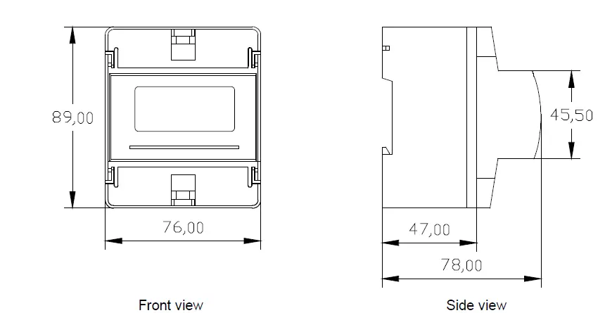
Notes:
Input signal: 19D-24D using a separate acquisition calculate for each measurement channel, to ensure consistent in use, for different load forms, it’s a variety of connection mode. Access wire shall be met 3 square mm.
Voltage input
Input voltage should not exceed the rated input voltage products 450V. Otherwise, you should use external VT. Suggest 1A fuse be installed in the voltage input side.
Current Input
Standard input current is 5A or 1A, if greater than 5A/1A should use external CT. When the CT is connected with other meters, make sure wiring methods be used in series.
Warning: Forbid to install a CT on the live feeder wire with open secondary leads. This can be extremely dangerous!
Before remove the current input connection, must be sure to disconnect the primary circuit or shorted secondary circuit of CT.
Sequence of wire
Warning: Please make sure that the input voltage and current corresponding to the same phase, sequence, and the same direction; Otherwise, the Values and symbols will be wrong! (Power and Energy) Always observe the physical orientation of CT (P1 – P2) when installing on the feeder wire. Always pay attention to wiring polarity and phasing when terminating the CT leads to the 19D-23C. S1 connect to Ix*, S2 connect to Ix. The input network configuration of instrument depends on the CT number of the system: in the condition of 2 CT, select the three-phase, three-lines two components; in the condition of 3 CT, select the three-phase, four-lines three component mode. Instrument connection mode, set of the instrument (programming input network NET) should be the same load wiring as measured wiring. Otherwise, the measurement instrument will lead to incorrect voltage or power.
Auxiliary power
19D-24D with universal (AC / DC) power input, if not for a special statement, we provide the 90-240AC/DC power interface for standard products, please ensure that the auxiliary power can match with meter to prevent unexpected damage.
- Suggest install 1A fuse in the fire line side.
- For the areas with poor power quality, suggest install lightning surge suppressor and rapid burst suppressor to prevent lightning strikes.
Connection Terminal
Upper connection terminal
| 5 | 6 | 7 | 8 | 9 | 10 |
| 485B | 485A | + | – |
- RS-485 (-)
- RS-485 (+)
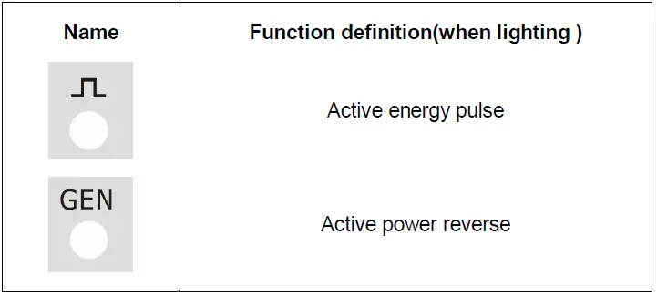
- Active energy pulse output (+)
- Active energy pulse output (-)
Lower connection terminal
| 4 | 3 | 2 | 1 |
| N | L |
- Auxiliary power supply
- Auxiliary power supply
Note:
The terminal pin definition may change depends on customer order; please refer to the label on the meter!
Typical Wiring

Note:
This connection drawing is for reference only; the actual connecting terminal please refer to the label on the rear part.
WARNINGS!
If power = -0.01 is shown for any of the phases and voltage and current are not zero for this phase, check out following points:
- Assure that A, B and C phases coincide in voltage and current.
- Correct polarity? Reverse the current transformer placed at this phase.
SCREEN DISPLAY
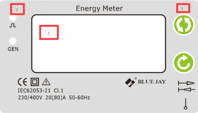
Screen description
Panel introduction
- Display measurement data
- Indicator light
- Button
Indicator light description
Screen pages’ description
| Screen No. | Screen interface | Description |
|
1 |  |
Total active energy |
|
2 | 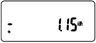 |
Total negative active energy. |
|
3 | 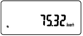 |
Total active reactive energy |
|
4 | 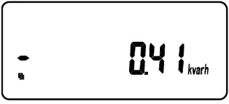 |
Total negative reactive energy |
|
5 |  |
Active energy for paid function |
|
6 |  |
Maximum demand for paid function |
|
7 | 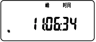 |
Current time |
|
8 |
| |
 Current voltage and other parameters
 |
Short press is the left key to switch the viewing interface;
Long press is the menu key to enter and modify parameters. |
|
Short press is the right key to switch the viewing interface;
Long press is the confirmation key to save the modified data. |
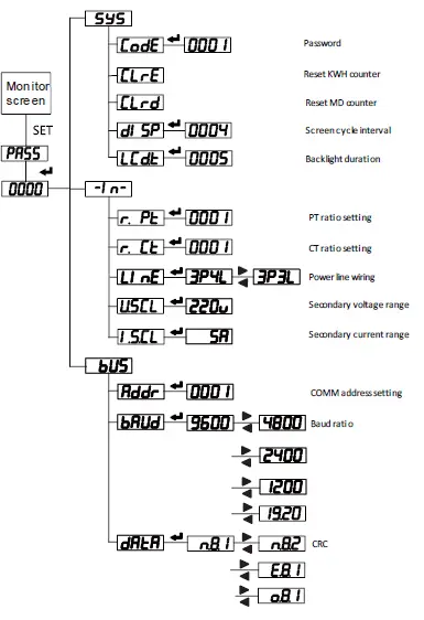
Main menu
In the case of measuring data, long press the “ ” key, and a prompt of “PASS” (that is, “password”) will appear, short press the “ ” key to enter the user-level password (the default is 0001), and long press the “ ” key to enter programming In the status, the instrument provides three types of input setting menu items: system factory commissioning (SYS), input (-IN-), communication (bus), and time (time), meter reading day (E.day), rate (E.SEG) and other additional setting menu items. Adopt LCD display layered menu structure management.
Description of menu characters
 (Password) User password (Password) User password |
|
|
|
|
|
|
 (System) System settings menu (for factory debugging, not open yet) (System) System settings menu (for factory debugging, not open yet) |
 (Code) Enter password (Code) Enter password |
 (Data) Communication parameter setting (Data) Communication parameter setting |
 (Address) Local communication address setting (Address) Local communication address setting |
|
|
|
|
|
|
|
|
|
|
 (I.scl) Select rated input current (I.scl) Select rated input current |
 (R.ct) Set the current multiplier (R.ct) Set the current multiplier |
 (R.pt) Set voltage ratio (R.pt) Set voltage ratio |
| (System) System settings menu (for factory debugging, not open yet) |
|
|
 (Error) Wrong input information
 (Input) User Display data settings menu
 (Bus) Communication settings menu
 (Baud) Communication baud rate
 (o.8.1) Indicates 8 data bits, 1 stop bit, odd parity
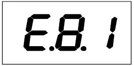 (e.8.1) Indicates 8 data bits, 1 stop bit, even parity
 (U.scl) Select rated input voltage
 (Type) What parameters to set
|
|
|
|
|
|
|
|
|
|
|
|
|
|
|
|
|
|
|
|
|
|
|
|
|
|
|
|
|
|
|
|
|
|
 (Para Corresponding parameter selection
 (Value) Set the corresponding alarm value
 (Code) Modify password value
 (Year) Set year
 (Month) Set month
 (Day) Set day
 (Date) Set date
 (Hour) Set hour
 (Min.) Set minute
 (Second) Set second
 (Seg,) Set segment
 Flat
Flat Valley
 Sharp
Sharp Peak
Peak Meter reading time setting
PULSE OUTPUT (OPTIONAL)
19D-24D provides 1* pulse output for the active energy.
The host / PLC / DI module can cumulative the data of both the active and reactive power energy sent by the pulse from opt coupler relay.
- Electrical specification: voltage VCC ≤ 48V, Iz ≤ 50mA.
- Pulse: 5000 imp / kWh, pulse up to 80ms. This means: When the device detects 1 kWh, the port will generate 5000 pulse
Note:
1 kWh energy is for secondary side energy data, if there have PT and CT accessed; primary side
| Voltage (V) | Current (A) | Pulse constant (imp / kWh) |
| 5 | 5000 | |
| 380 or 220 | ||
| 1 | 20000 | |
| 5 | 20000 | |
| 100 | ||
| 1 | 80000 | |
Example: In measure time “T”, the received total pulse is “N”, Primary side input of voltage is 10Kv Primary side input of current is 400A.
Secondary side measurement range is 100V and 5A.
In the time “T”, energy accumulated is: N / 20000 × 100 × 80
COMMUNICATION INTERFACE
Connection for RS485 BUS
The composition of the RS-485 cabling must be carried out with a meshed screen cable (minimum 3 wire), diameter of not less than 0.5mm2, with a maximum distance of 1,200 m between the 19D-24D… and the master unit. This Bus may connect a maximum of 32pcs.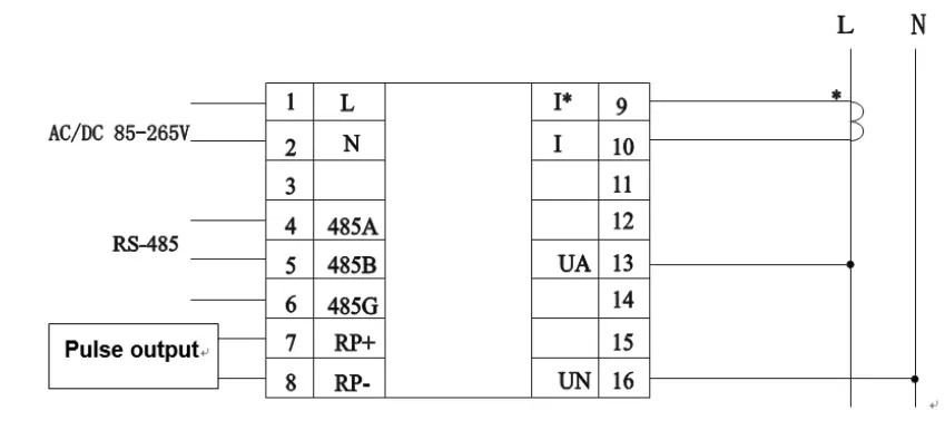
Notes:
- For communication with the master unit, user can choose RS-485 to RS-232 converter or RS485 to USB adapter to use.
- For expand the number of devices in the communication network, a signal repeater can be used. -. RS485 PIN number is 58,59,60
- Due to product modifications or special requirements, the interface pin place may be change. For details, please refer to product label on the rear side
MODBUS © Protocol
Modbus RTU Frame Format:
| Address code | 1 BYTE | Slave device address 1-247 |
| Function code | 1 BYTE | Indicates the function codes like read coils / inputs |
| Data code | 4 BYTE | Starting address, high byte Starting address, low byte Number of registers, high byte Number of registers, low byte |
| Error Check code | 2 BYTE | Cyclical Redundancy Check ( CRC ) |
MODBUS FUNCTIONS
| Code | Meaning | Description |
| FUNCTION 01 | Read Coil Status | Only valid when equipped DO port |
| FUNCTION 02 | Read Input Status | Only valid when equipped DI port |
| FUNCTION 03 | Reading of n Words | This function permits to read all the electrical parameters |
| FUNCTION 05 | Force Single coil | When DO in remote control mode can work |
|
FUNCTION 06 |
Preset Single register | Disable in default If need valid this code, please contact Blue Jay Sales Team before your order! |
Note: Float data follow IEEE754, float low bit first, high bit next. (CD AB)
Register Map
Basic power data—Primary Side
| Register | Data | Byte mode | Instruction | |
| 0x00 | U | float | 2 | Phase to Line Voltage, Unit: V |
| 0x0c | I | float | 2 | Current, Unit: A |
| 0x12 | P | float | 2 | Active power, Unit: kw |
| 0x1a | Q | float | 2 | Reactive power, Unit: kvar |
| 0x22 | S | float | 2 | Apparent power, Unit: kva |
| 0x2a | PF | float | 2 | Power factor, 0~1.000 |
| 0x32 | FR | float | 2 | Frequency, Unit:0.01Hz |
| 0x34 | Ep+ | float | 2 | Positive active energy, Unit: kWh |
| 0x36 | Ep- | float | 2 | Negative active energy, Unit: kWh |
| 0x38 | Eq+ | float | 2 | Inductive reactive power, Unit: kVarh |
| 0x3a | Eq- | float | 2 | Capacitive reactive power |
Basic power data—Secondary Side
| Register | Data | Byte mode | Instruction | |
| 0x100 | Ua | int | 1 | Voltage, Unit: 0.1V Current, Unit:0.001 A |
| 0x106 | Ia | int | 1 | |
| 0x109 | Pa | int | 1 | Active power, Unit: W |
| 0x10d | Qa | int | 1 | Reactive power, Unit: Var |
| 0x111 | Sa | int | 1 | Apparent power, Unit: Va |
| 0x115 | PFa | int | 1 | Power factor, 0~1.000 |
| 0x119 | FR | int | 1 | Frequency, unit:0.01hz |
| 0x11a | Ep+ | int | 2 | Positive active energy, Unit: Wh |
| 0x11c | Ep- | int | 2 | Negative active energy, Unit: Wh |
| 0x11e | Eq+ | int | 2 | Inductive reactive power, Unit: Varh |
| 0x120 | Eq- | int | 2 | Capacitive reactive power |
Advanced electrical parameter (optional function)
| Register | Data | Byte mode | Instruction | |
| 0x300 | Pde | float | 2 | Present active power demand, Unit: W |
| 0x302 | Qde | float | 2 | Present reactive power demand, Unit: var |
| 0x304 | Sde | float | 2 | Present apparent power demand, Unit: VA |
| 0x306 | PzM1 | float | 2 | Active power demand in present month |
| 0x308 | QzM1 | float | 2 | Reactive power demand in present month |
| 0x30a | SzM1 | float | 2 | Apparent power demand in present month |
| 0x30c | PzM2 | float | 2 | Active power demand in last month |
| 0x30e | QzM2 | float | 2 | Reactive power demand in last month |
| 0x310 | SzM2 | float | 2 | Apparent power demand in last month |
| 0x312 | PzM3 | float | 2 | Active power demand in month before last month |
| 0x314 | QzM3 | float | 2 | Reactive power demand in month before last month |
| 0x316 | SzM3 | float | 2 | Apparent power demand in month before last month |
| 0x318- 0x31F | float | 2 | Reversed | |
Multi- tariffs ratio data (optional function)
| Register | Data | Byte mode | Instruction | |
| 0x400 | E0_tol | long | 2 | Total cumulative energy |
| 0x402 | E0_T1 | long | 2 |
T1-T4 cumulative Energy record |
| 0x404 | E0_T2 | long | 2 | |
| 0x406 | E0_T3 | long | 2 | |
| 0x408 | E0_T4 | long | 2 | |
| 0x40a | E1_tol | long | 2 | Total energy of present month |
| 0x40c | E1 _T1 | long | 2 |
T1-T4 Energy record of present month |
| 0x40e | E1 _T2 | long | 2 | |
| 0x410 | E1 _T3 | long | 2 | |
| 0x412 | E1_T4 | long | 2 | |
| 0x414 | E2_tol | long | 2 | Total energy of last month |
| 0x416 | E2_T1 | long | 2 |
T1-T4 Energy record of last month |
| 0x418 | E2_T2 | long | 2 | |
| 0x41a | E2_T3 | long | 2 | |
| 0x41c | E2_T4 | long | 2 | |
| 0x41e | E3_tol | long | 2 | Total energy of the month before last month |
| 0x420 | E3_T1 | long | 2 | T1-T4 Energy record the month before last month |
| 0x422 | E3_T2 | long | 2 | |
| 0x424 | E3_T3 | long | 2 | |
| 0x426 | E3_T4 | long | 2 | |
Notes:
- The data can be read out depends on your multi-function meter model, please refer to the corresponding product manual before build your software.
- Some software has different definitions of the start bit of register address, there will be offset, please add 1 for the right address. To get more info, please contact technical support.
Example
Host inquiry slave device
| Addr . | Func . | Data Address high | Data Address low | Data Number high | Data number low | CRC16 low | CRC1 6 high |
| 0CH | 03H | 00H | 00H | 00H | 06H | C4H | D5H |
PC user ask upload UA, UB, UC, IA, IB, IC
Slave device response
| Addr. | Func. | Byte count | Data1 high | Data1 low | Data2 high | Data2 low | Data3 high | Data3 low |
| 0CH | 03H | 0CH | 03H | E8H | 03H | E9H | 03H | E8H |
| Data4 high | Data4 low | Data5 high | Data5 low | Data6 high | Data6 low | CRC16 low | CRC16 high | |
| 13H | 84H | 13H | 88H | 13H | 8AH | A6H | D6H |
Show the data:
- UA=3E8H (100.0)
- UB=3E9H (100.1)
- UC=3E7H (99.9)
- IA=1384H (4.996)
- IB=1388H (5.000)
- IC=138AH (5.002)
Notes:
- Blue Jay disable the 06 function in default setting, if Activated the write command, please check the host device program to avoid the meaningless write operation, that may reduce the reduce the register working life.
- When the write is unsuccessful, no return data from the slave device. In this addition, please re-send write inquiry again.
SAFETY CONSIDERATIONS
All installation specification described at the previous chapters named: INSTALLATION AND STARTUP, INSTALLATION MODES and SPECIFICATIONS. Please note that with the instrument powered on, the terminals could be dangerous to touching and cover opening actions or elements removal may allow accessing dangerous parts. This instrument is factory-shipped at proper operation condition.
- The device must have a professional installation and maintenance
- Any operation of the device, you must cut off the input signal and power;
MAINTENANCE
The 19D-24D single phase energy meter does not require any special maintenance. No adjustment, maintenance or repairing action should be done when the instrument is open and powered on, should those actions are essential, high-qualified operators must perform them. Before any adjustment, replacement, maintenance or repairing operation is carried out, the instrument must be disconnected from any power supply source. When any protection failure is suspected to exist, the instrument must be immediately put out of service. The instrument’s design allows a quick replacement in case of any failure.
TECHNICAL SERVICE
FAQ’s
- Once cabled and connected is seen to give a correct voltage and current reading, but shows negative values for active power (generation).
This is an error with the cabling for the current transformer secondary; the direction of the transformer current has to be respected as shown in the connection diagram. The current transformers have a two face primary; the current must pass from P1 to P2 giving the result in secondary (S1 and S2) of 5 amps.
The error stems from:- The current transformers have been incorrectly installed. As a result, it gives the direction of the current as passing from P2 to P1; to resolve this problem, the current transformer does not have to be dismantled and installed again, but the transformer secondary (S1 and S2) just has to be inverted.
- The connection of the current secondary in the current transformers have been incorrectly connected; to resolve this problem just connect the S1 transformer secondary to the S1 on the meter and the S2 on the current transformer to the S2 on the meter.
- Once cabled and connected, is seen to give an incoherent Power factor and CosΦ reading (-0.01 or similar).
This is again a current transformer and voltage phase connection error phase A, must correspond to the current transformer installed in phase A; phase B, must correspond to the current transformer installed in phase B; and phase C, must correspond to the current transformer installed in phase C. This connection terminal is clearly shown on the area side of the device. - The measuring voltage and is displaying the secondary voltage (for example 110 volts).
Ensure that the voltage Transformer ratio has been correctly set. - Device does not correctly display the current reading. It shows values varying between 0 to 5 amps of current. Ensure that the Current Transformer ratio has been correctly set.
Calculation formula of electrical parameter
| Formula | Parameter |
|
|
Voltage RMS value |
|
|
Current RMS value |
|
|
Total active power cycle average |

|
Single-phase apparent power cycle average |
|
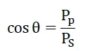
|
Power factor |
|
| Reactive power (Pq is positive and the direction cannot be determined; P algorithm can be used to shift the voltage component by 90o) |
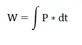
|
Electric energy |
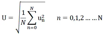
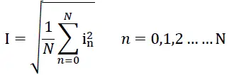
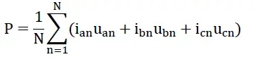

Note: In above formula, N for sampling points in one AC wave.
For any inquiry about the instrument performance or any failure, contact to Blue Jay’s technical service.
Blue Jay – After-sales service
E-mail: [email protected]
Tel: +0086-023-67628702
www.cqbluejay.com
Add: 1802,Building 2,No.88,Jianxin East Road,Chongqing,400020,China
Email:[email protected]


